Poweduction Heat Controler - Temperature regulator GYS - Free user manual and instructions
Find the device manual for free Poweduction Heat Controler GYS in PDF.
| Product type | Temperature controller |
| Brand | GYS |
| Model | Poweduction Heat Controler |
| Use | Smart box acting as thermostat for Powerduction 110/160LG |
| Regulation range | 80°C to 350°C (in 10°C steps) |
| Power supply | 15V 50mA (via Power connector) |
| Inputs | 2 thermocouples, pyrometer (optional), external switch (REMOTE) |
| Outputs | Dry contact OK/Safety (5A/30V), display on Powerduction |
| Operating modes | Manual (via heating authorization button) and automatic (via Start input) |
| Emissivity adjustment | Blue potentiometer (screw) for pyrometer |
| Display | Highest measured temperature (via Powerduction) |
| Safety | Faults E11 (rapid temperature drop) and E12 (temperature not evolving), shutdown if thermocouple disconnected |
| Maintenance | Dust regularly, check connections by qualified personnel, clean with dry cloth |
| Spare parts and repairability | Inductors and ferrites consumables not covered by warranty; power cable replaceable by qualified after-sales service |
| Warranty | 2 years parts and labor (excluding misuse) |
| Compliance | CE, EAC |
| Disposal | Selective collection (do not throw in household waste) |
Frequently Asked Questions - Poweduction Heat Controler GYS
User questions about Poweduction Heat Controler GYS
0 question about this device. Answer the ones you know or ask your own.
Ask a new question about this device
Download the instructions for your Temperature regulator in PDF format for free! Find your manual Poweduction Heat Controler - GYS and take your electronic device back in hand. On this page are published all the documents necessary for the use of your device. Poweduction Heat Controler by GYS.
USER MANUAL Poweduction Heat Controler GYS
natural_image
Line drawing of a rectangular electronic device with mounting feet and a central housing (no text or symbols)FR 1-10
EN 11-17
DE 18-25
ES 26-33
RU 34-41
NL 42-49
IT 50-57
natural_image
Technical line drawing of a rectangular electronic device with ports and a red arrow pointing to the side (no text or symbols)natural_image
Technical diagram of a mechanical or electrical component with no visible text, numbers, or symbols.FONCTIONNEMENT AVEC 2 THERMOCOUPLES (FOURNIS) (FIG I)
natural_image
Technical illustration of a device with two connected components and a separate terminal block (no text or symbols)CONDITIONS DE GARANTIE
This manual contains safety and operating instructions, to be followed for your safety. Please read it carefully before using the device for the first time and keep it in a safe place for future reference. Read and understand the following safety recommendations before using or servicing the unit. Any change or servicing that is not specified in the instruction manual must not be undertaken. The manufacturer is not liable for any injury or damage caused due to non-compliance with the instructions featured in this manual. If there is any issue or uncertainty, please consult a qualified individual to operate the equipment correctly. This machine should only be used for operations comprised within the limits indicated on the machine and in the instruction manual. The operator must observe the safety precautions. In case of inedaquate or unsafe use, the manufacturer cannot be held liable for damage or injury. Any other uses not specified in this manual is forbidden, and possibly dangerous. The product is semi automatic and requires the presence of an operator.
This unit can be used by children aged 8 or over and by people with reduced physical, sensory or mental capabilities or lack of experience or knowledge, if they are properly monitored or if instructions for using the equipment safely have been read and risks made aware of. Children must not play with the product. Cleaning and maintenance should not be performed by an unsupervised child.
Do not use the charger if the mains cable or plug is damaged.
Do not cover the device.

People wearing pacemakers are advised to not come close to the machine. Risk of disruption of pacemaker operations when close to the machine.
Consult a doctor before getting close to induction heaters.
Warning ! Very hot surface. Risk of burns.
- The parts and pieces that have just been heated are hot and may cause burns when manipulated.
- Do not touch any hot parts with your hands.
- Wait for the parts and pieces to cool down before handling them.
- Check that jewellery (such as wedding rings) or other metal pieces do not get close to the induction heating machine or the inductor when switched on.
- Remove any jewellery or any metal object from yourself before using this machine
• People with metal implants should not use this machine. - In case of burns, rinse with water abundantly and see a medical doctor as soon as possible.

Connection:
- This machine must be connected to an earthed socket.


Maintenance:
- If the power cable is damaged, it must be replaced by the manufacturer, its after sales service or an equally qualified person to prevent danger.
- Warning! Always disconnect from the mains before performing maintenance on the device. High Voltage and Currents inside the machine.
- Remove the casing on a regular basis, to remove any excess dust. Take this opportunity to have the electrical connections checked by a qualified person, with an insulated tool.
- Do not use solvents or any agressive cleaning products.
- Clean the device's surfaces with a dry cloth.
Regulations:
• Device complies with europeans directives.
- The certificate of compliance is available on our website.
• EAC Conformity marking (Eurasian Economic Community).
Waste management:
- This product should be disposed of at an appropriate recycling facility. Do not throw away in a domestic bin.
- The product's manufacturer contributes to the recycling of its packaging by contributing to a global recycling system.
• This product should be recycled appropriately
GENERAL DESCRIPTION
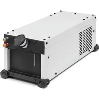
The Powerduction Heat Controller is an intelligent box that acts like a thermostat on the Powerduction 110/160LG. It regulates the temperature of the part to be heated between 80^ and 350^ .
POWERDUCTION CONNECTION
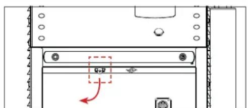
natural_image
Technical diagram of a device rear panel with mounting holes and a red arrow indicating direction (no text or symbols)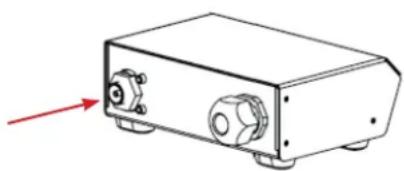
natural_image
Line drawing of a rectangular electronic device with ports and a red arrow pointing to the left side (no text or symbols)- Disconnect the pedal from the Powerduction and then connect it to the Powerduction Heat Controller.
natural_image
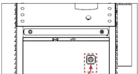
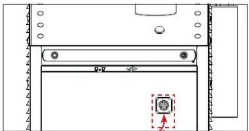
Technical line drawing of a mechanical component with no visible text or symbols- Connect the product cable to the front panel of the Powerduction.
- The Powerduction Heat Controller is connected. Select an operating mode.
Set the switch (8) to ON and press the heater enable button (9) (pedal activation).
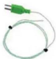
Connect the supplied thermocouples to the side of the interface:
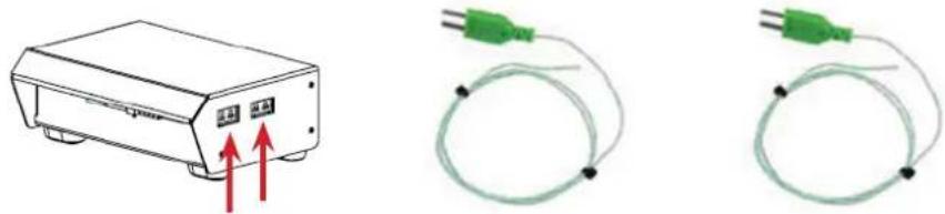
Thermocouples should be installed as close as possible to the area under the inductor ferrite.
It is recommended to drill the workpiece below the area to be heated with a drill bit of diameter 2 to a depth of about 1 to 2mm.
If switches (1) and (2) are in the OFF position, the Powerduction Heat Controller displays the highest measurement on the Powerduction 110/160LG.
OPERATION WITH A PYROMETER (ref. 064119) (FIG I)
- Set switches (2), (7) and (8) to ON.
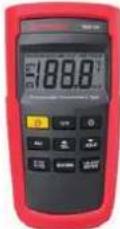
- Connect a thermocouple (supplied) to a thermocouple thermometer (not supplied).

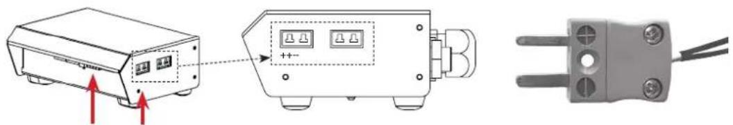
- Connect the pyrometer to the Powerduction Heat Controller (2 connectors)

When plugging the pyrometer, observe the connection direction of the thermocouple connector.
The positive terminal of the connector should be towards the front of the Powerduction Heat Controller, the negative terminal towards the rear.
-
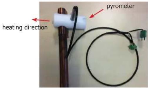
Install the pyrometer on the Powerduction 110/160LG lance using the adapter and nylon screws provided.
-
Install the thermocouple on the part to be heated as close as possible to the ferrite of the inductor (it is recommended to drill the part below the area to be heated with a 2 mm diameter drill to a depth of approximately 1 to 2 mm to insert the thermocouple).
Emissivity adjustment (while heating and staying in the same place on the workpiece)
- Turn the screw of the blue potentiometer (see wiring diagram) with a flat screwdriver 2.5 until the value displayed by the thermometer is identical to the value displayed on the Powerduction 110/160LG (+/- 3°C).
- Once the setting has been made, remove the thermocouple from the piece to be heated.
Adjusting the emissivity is essential for a good measurement.
By turning the potentiometer clockwise, the displayed setpoint on the Powerduction 110/160LG will decrease and the temperature of the part to be heated will increase.
By turning the potentiometer anticlockwise, the displayed setpoint will increase and the room temperature will decrease.

It is advisable to point the heater in the opposite direction to the pyrometer location (see photo opposite).
text_image
pyrometer heating directionConnecting diagram
text_image
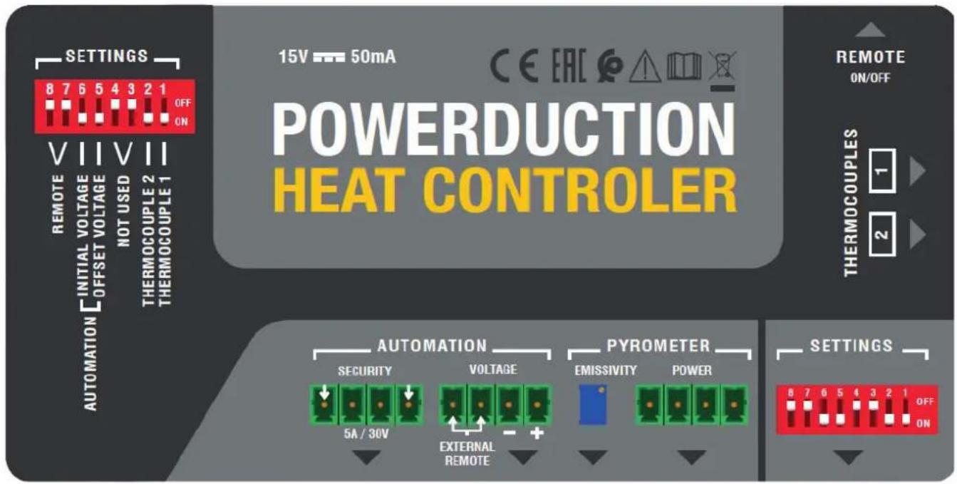
SETTINGS 8 7 6 5 4 3 2 1 OFF ON VIIIVII REMOTE INITIAL VOLTAGE NOT USED THERMOCOUPLE 2 THERMOCOUPLE 1 AUTOMATION OFFSET VOLTAGE REMOTE ON/OFF POWERDUCTION HEAT CONTROLLER 15V 50mA CE EAC REMOTE ON/OFF THERMOCOUPLES 1 2 AUTOMATION SECURITY VOLTAGE 5A / 30V EXTERNAL REMOTE PYROMETER EMISSIVITY POWER OPTIONS 8 7 6 5 4 3 2 1 OFF ON| Automation | Security dry contact |
| Voltage this connector allows you to connect a pyrometer to measure voltage or to connect an external switch (which replaces the pedal) | |
| Pyrometer | Emissivity This potentiometer allows to modify the setting (thanks to the screw) and to refine the temperature measurement according to the emissivity of the part to be heated. |
| Power this connector is used to connect the pyrometer (e.g. pyrometer - ref 064119) |
Switch setting
| 1 sif ON cancellation of thermocouple 2 measurement | { If both are OFF, the highest measurements is displayed. |
| 2 if ON cancellation of thermocouple 1 measurement | |
| 3 et 4 offline | |
| 5 if ON activation of an OFFSET for the initial display at 100°C (button 5 has priority over all the others) (do not use for a thermocouple measurement) | |
| 6 if ON and switch 5 OFF initial display at 0 (do not use for thermocouple measurement) | |
| 7 et 8 if ON activation of the footswitch connected to the REMOTE input | |
OPERATION WITH PYROMETER ANALOG OUTPUT (not supplied)
Use a pyrometer sensor with an analog output directly on the product connectors (to be adapted according to the datasheet of the pyrometer used)
Example of a current measuring pyrometer
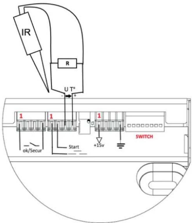
text_image
IR R U T° 1 1 1 ok/Secur Start +15V SWITCHIn this case, the value of the shunt R resistance on U T° must be adapted according to the setpoint and the desired accuracy (10 mV per Degree).
Correspondence table
| Voltage U T° Temperature in Celsius Temperature in Fahrenheit | ||
| 1 V 0°C 32°F | ||
| 2 V 100°C 210°F | ||
| 3 V 200°C 390°F | ||
| 4 V 300°C 570°F | ||
| 4.5 V 350°C 660°F | ||
MANUAL MODE (FIG II & III)

For an optimal use of the product, it is recommended to set the power between 30 and 50%.
To return to the «outdoor temperature control» mode:
- Press and hold the heating enable button (9) for 5 seconds.
- The button blinks every second and «rEG» is displayed.
The button on the lance (10) and the pneumatic pedal (11) are deactivated in this mode.
To set and then activate the heater :
- Adjust the control setpoint: Press the adjustment buttons (14).
The regulation setpoint varies from 80^ C to 350^ C (default value at 250^ C) in 10^ C steps. It is displayed for one second.
- Adjust the heating power setpoint (%): hold down the «Inductor change» button (13) and press the adjustment buttons (14). The heating power setpoint ranges from 10% to 100% (default 50%). The power is updated on the bar graph.
- Activate the heater: connect the pneumatic pedal (11) of the generator to the interface and press it. The minimum power light (12) flashes at 10 Hz to indicate that the power is active.
It is possible to re-adjust the heater when it is active. In this case, it is not necessary to perform step 3. The heating in progress adapts to his new instructions.
AUTOMATION MODE (FIG II)
The product can be controlled by an automaton (see pin assignment) via the external interface.
To enter the «outdoor temperature control» mode (see pin assignment below):
- Switch on the product.
- Wait for the end of the start-up phase 5 s.
- Close the Start contact.
- Wait for the OK/Secur output to close (500 ms).
- Release the Start contact after detecting the OK/Secur.
- Check that the OK/Secure output remains closed.
The product enters the «external control mode» and generates a melody.
The heat enable button (9) and the LED on the lance button (10) flash once per second as long as the mode is activated.
To set the temperature setpoint and heating power: perform the same operation as in manual mode.
To activate the heater :
- Close the start switch. The product will heat until the set temperature is reached and regulated.
If the product detects a fault, then the OK/Secur output opens and the heater stops.
To acknowledge the fault, open the Start contact and press the heater enable button (9).
The product returns to «regulation» mode.
BROACHING
text_image
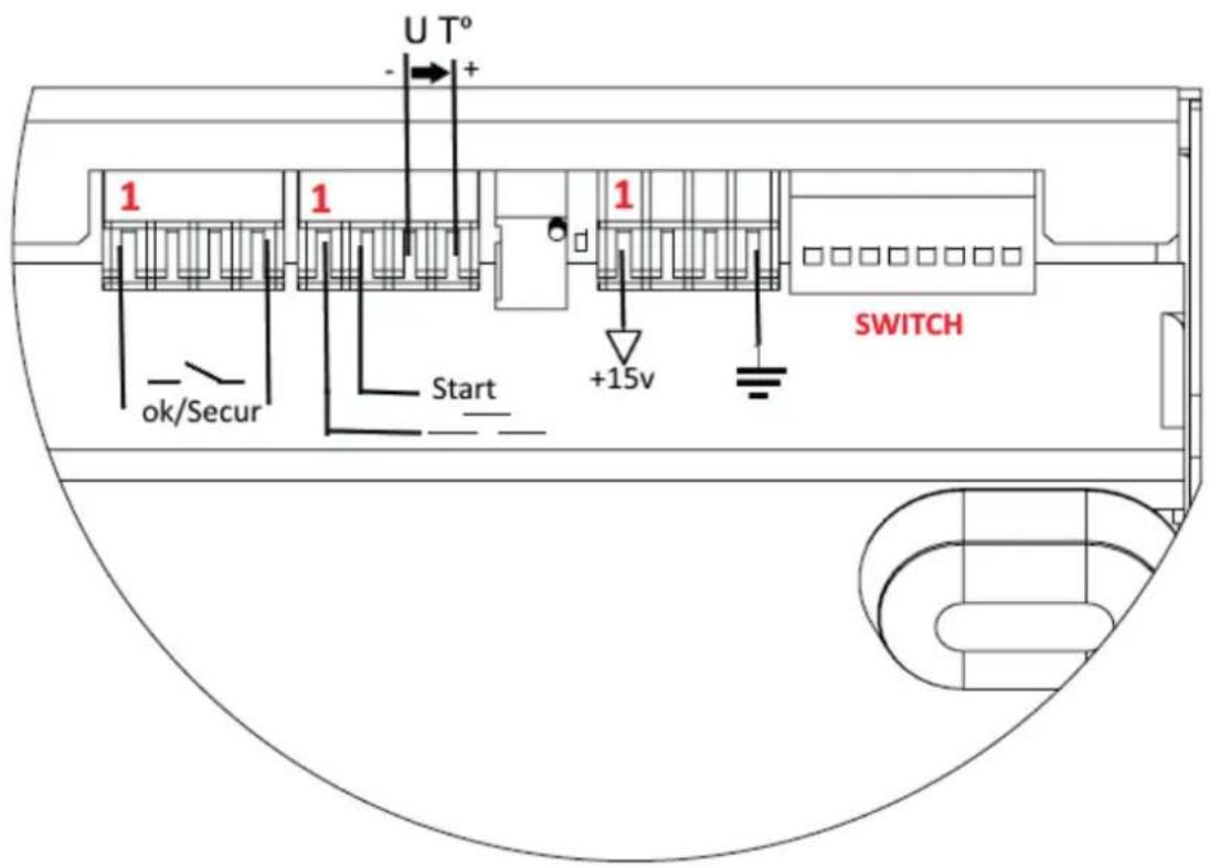
U T° - + 1 1 1 +15v ok/Secur Start SWITCH| Function No. of the wire | Type Electrical settings Values Logic | ||||
| Generator ready OK/Secur | 1/3 Digital output Type | Permissible direct current | Dry contact 5 A 30 V | Closed Ready-to-heat generator | |
| Opened Generator fault | |||||
| Earth 8 Earth Earth Terre Earth | |||||
| Start 9/8 Digital input Residual voltage (open circuit) | Input impedance | 15 V | Requires the use of a dry contact: a closed contact activates the heater. | ||
| 3.5 kΩ | |||||
| Regulation voltage U T° | 11 - / 14+ | Analog input | Maximum input voltage | 5 V | Image input of the measured temperature. |
| Input impedance | 5.4 kΩ | ||||
| Accuracy | +/-5% | See correspondence table | |||
| Interface power | 12/13 | Continuous power supply | Output voltage | 15 V | |
| Output impedance | 100 Ω | ||||
DIAGRAM OF AUTOMATION START UP
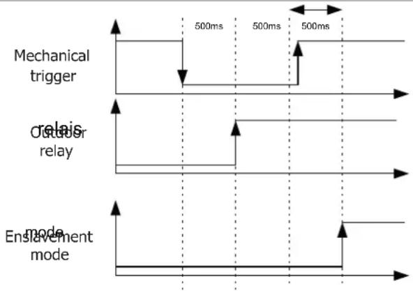
flowchart
graph TD
    A["Mechanical trigger"] --> B["Relais"]
    B --> C["Relais"]
    C --> D["Enable mode"]
    style A fill:#f9f,stroke:#333
    style B fill:#ccf,stroke:#333
    style C fill:#cfc,stroke:#333
    style D fill:#fcc,stroke:#333
SAFETY AND DEVICE FAILURE
- If the temperature input does not change after 5 s, the product is set to fault "E12".
- If a thermocouple breaks, then the regulation stops because the voltage U T° exceeds the maximum voltage of 4.9 V.
- f the temperature drops significantly within a short period of time (e.g. when thermocouple probes go out of order), the heating stops and the product goes to fault "E11".
- In order to have the most accurate control possible, the measuring point(s) must be as close as possible to the inductor.
- This is the reason for the 2 thermocouples on the external interface.
- The display shows the highest temperature measured by the sensors.
WARRANTY
The warranty covers faulty workmanship for 2 years from the date of purchase (parts and labour).
The warranty does not cover:
- Transit damage.
- Normal wear of parts (eg. : cables, clamps, etc..).
- Damages due to misuse (power supply error, dropping of equipment, disassembling).
- Environment related failures (pollution, rust, dust).
In case of failure, return the unit to your distributor together with:
- The proof of purchase (receipt etc ...)
- A description of the fault reported
text_image
Technical diagram showing a device with labeled components and an arrow indicating direction or movement, possibly for assembly or labeling.
natural_image
Technical line drawing of a rectangular electronic device with ports and a red arrow indicating direction (no text or symbols)natural_image
Technical line drawing of a door with a highlighted circular component and arrow indicator (no text or symbols)natural_image
Illustration of a device with red arrows indicating upward motion, alongside two green electrical probes connected by wires (no text or symbols)natural_image
Diagram showing a device with two ports and a separate electrical terminal block, no text or symbols present.natural_image
Technical line drawing of a rectangular electronic device with ports and a red arrow pointing to the left side (no text or symbols)- Desconecte el pedal del Powerduction y conéctelo al Powerduction Heat Controller.
natural_image
Technical line drawing of a mechanical or architectural component with no visible text, numbers, or symbols.natural_image
Line drawing of a rectangular electronic device with two red arrows pointing upward, no text or symbols present.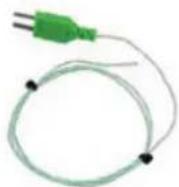

natural_image
Diagram showing a device with two ports and a separate electrical terminal block, no text or symbols present.MODO MANUAL (FIG II & III)

natural_image
Technical diagram of a mechanical or electronic component with no visible text, numbers, or symbols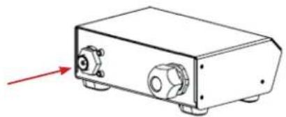
natural_image
Technical line drawing of a rectangular electronic device with ports and a red arrow pointing to the left side (no text or symbols)natural_image
Technical diagram of a computer monitor with a highlighted screw and indicator lights (no text or symbols)natural_image
Line drawing of a rectangular electronic device with two red arrows pointing upward, no text or symbols present.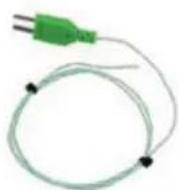
natural_image
Diagram showing a device with two ports and a separate electrical terminal block, no text or symbols present.natural_image
Technical line drawing of a rectangular electronic device with ports and a red arrow pointing to the left side (no text or symbols)natural_image
Technical line drawing of a door with a highlighted component and directional arrow (no text or symbols)natural_image
Line drawing of a rectangular electronic device with two red arrows pointing upward, no text or symbols present.