FAFW3001LW - Washing machine FRIGIDAIRE - Free user manual and instructions
Find the device manual for free FAFW3001LW FRIGIDAIRE in PDF.
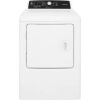
| Product Type | Automatic Front-Loading Washing Machine |
| Brand | Frigidaire |
| Model | FAFW3001LW |
| Dimensions (H x W x D) | 91.5 cm x 68.5 cm x 70.5 cm (door closed) |
| Weight | Approximately 70 kg (estimated) |
| Power Supply | 120 V, 60 Hz, single-phase AC |
| Required Circuit | 15 A individual circuit with time-delay fuse or circuit breaker |
| Power Outlet | 3-prong grounding type outlet |
| Water Pressure | 206.8 to 827.4 kPa (30 to 120 psi) |
| Minimum Drain Height | 61 cm (24 in.) |
| Maximum Drain Height | 244 cm (96 in.) |
| Minimum Drain Capacity | 64.3 L/min (17 gal/min) |
| Leveling | Adjustable legs with included universal wrench |
| Included Accessories | Transport caps, anti-siphon disc, drain hose clip |
| Optional Accessories | Storage drawer (CFWD15A), stacking kit (STACKIT4X), drain hose extension, mobile home installation kit |
| Packaging Materials | Styrofoam base, shipping bolts, spacer blocks |
| Safety | Mandatory grounding, anti-siphon device, precautions against fire and suffocation hazards |
| Maintenance and Cleaning | Clean water inlet filters, check supply hoses |
| Repairability | Replacement parts available from the dealer or after-sales service |
| Warranty | Consult the use and care guide for warranty details |
Frequently Asked Questions - FAFW3001LW FRIGIDAIRE
User questions about FAFW3001LW FRIGIDAIRE
0 question about this device. Answer the ones you know or ask your own.
Ask a new question about this device
Download the instructions for your Washing machine in PDF format for free! Find your manual FAFW3001LW - FRIGIDAIRE and take your electronic device back in hand. On this page are published all the documents necessary for the use of your device. FAFW3001LW by FRIGIDAIRE.
USER MANUAL FAFW3001LW FRIGIDAIRE
natural_image
Silhouette illustration of various household appliances including washing machines, refrigerators, and a refrigerator (no text or symbols)TABLE OF CONTENTS
Important Safety Instructions 2-3
Installation Requirements 4-6
Installation Instructions 7-10
Accessories....11
Notes 12
Français ....13
Español 25

WARNING
Please read all instructions before using this washer.
Recognize safety symbols, words and labels
Safety items throughout this manual are labeled with a WARNING or CAUTION based on the risk type as described below:
Definitions
This is the safety alert symbol. It is used to alert you to potential personal injury hazards. Obey all safety messages that follow this symbol to avoid possible injury or death.

DANGER
DANGER indicates an imminently hazardous situation which, if not avoided, will result in death or serious injury.

WARNING
WARNING indicates a potentially hazardous situation which, if not avoided, could result in death or serious injury.

CAUTION
CAUTION indicates a potentially hazardous situation which, if not avoided, may result in minor or moderate injury.

IMPORTANT
IMPORTANT indicates installation, operation or maintenance information which is important but not hazard-related.

Installation Checklist
Shipping Hardware
☐ Foam shipping support (under wash tub) removed and stored
☐ Shipping bolts and spacers removed from rear of appliance and stored
☐ Hole plugs (shipped in bag in drum) installed in holes in backsheet
Leveling
☐ Washer is level, side-to-side and front-to-back
□ Cabinet is setting solid on all corners
Water Supply
☐ Use only new hoses and verify rubber sealing washers are installed
☐ HOT supply is connected to HOT inlet and COLD supply is connected to COLD inlet
☐ HOT and COLD water supply turned on
☐ No leaks present at water supply connections or appliance inlet connections - recheck in 24 hours
Drain
☐ Stand pipe or wall drain height minimum 24"
☐ Anti-siphon disc (shipped in drum) installed on drain hose
☐ Drain hose secured in place with cable tie (shipped in drum)
Electrical Power
House power turned on
□ Washer plugged in
Final Checks
☐ Installation Instructions and Use and Care Guide read thoroughly
☐ Door locks and water enters drum when cycle starts
☐ Registration card sent in

NOTE
The electrical service to the washer must conform with local codes and ordinances and the latest edition of the National Electrical Code, ANSI/NFPA 70, or in Canada, the Canadian Electrical Code C22.1 part 1.

WARNING
SUFFOCATION HAZARD
Destroy the carton and plastic bags after the washer is unpacked. Children might use them for play. Cartons covered with rugs, bedspreads, or plastic sheets can become airtight chambers causing suffocation. Place all materials in a garbage container or make materials inaccessible to children.

CAUTION
EXCESSIVE WEIGHT HAZARD
To avoid back or other injury, have more than one person move or lift the washer.

WARNING
FIRE HAZARD
For your safety the information in this manual must be followed to minimize the risk of fire or explosion or to prevent property damage, personal injury or loss of life. Do not store or use gasoline or other flammable vapors and liquids in the vicinity of this or any other appliance.

IMPORTANT
The instructions in this manual and all other literature included with this washer are not meant to cover every possible condition and situation that may occur. Good safe practice and caution MUST be applied when installing, operating and maintaining any appliance. Maximum benefits and enjoyment are achieved when all the Safety and Operating Instructions are understood and practiced as a routine with your laundering tasks.
Save these instructions for future reference.
Tools and materials needed for installation:
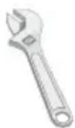
Adjustable wrench
OR OR AND AND


3/8" or 10 mm box wrench
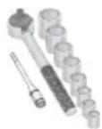
Ratchet and socket set

Adjustable pliers
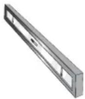
Carpenter's level

Inlet hose (x2)

NOTE
Hoses are not included with washer purchase. See "Accessories" section for various inlet hose kits to fit your specific installation.
INSTALLATION REQUIREMENTS
Electrical system requirements
CIRCUIT - Individual, properly polarized and grounded 15 amp. branch circuit fused with 15 amp. time delay fuse or circuit breaker.
POWER SUPPLY - 2 wire, with ground, 120 volt single phase, 60 Hz, Alternating Current.

NOTE
Because of potentially inconsistent voltage capabilities, the use of this washer with power created by gas powered generators, solar powered generators, wind powered generators or any other generator other than the local utility company is not recommended.
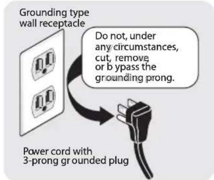
OUTLET RECEPTACLE - Properly grounded 3-prong receptacle to be located so the power supply cord is accessible when the washer is in an installed position.
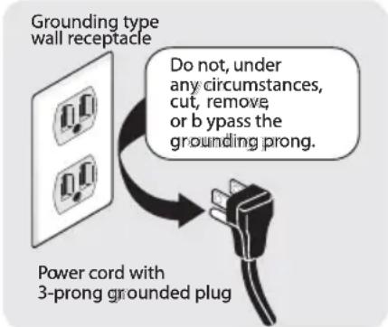
text_image
Grounding type wall receptacle Do not, under any circumstances, cut, remove, or bypass the grounding prong. Power cord with 3-prong grounded plug
NOTE
GFI (Ground Fault Interrupter) receptacle is not required.
Ground requirements

WARNING
ELECTRICAL SHOCK HAZARD
Improper connection of the equipment grounding conductor can result in a risk of electrical shock. Check with a licensed electrician if you are in doubt as to whether the appliance is properly grounded.
1 The washer MUST be grounded. In the event of malfunction or breakdown, grounding will reduce the risk of electrical shock by a path of least resistance for electrical current.
2 Since your washer is equipped with a power supply cord having an equipment-grounding conductor and a grounding plug, the plug MUST be plugged into an appropriate, copper wired receptacle that is properly installed and grounded in accordance with all local codes and ordinances or in the absence of local codes, with the National Electrical Codes, ANSI/NFPA 70 (latest edition). If in doubt, call a licensed electrician. DO NOT cut off or alter the grounding prong on the power supply cord. In situations where a two-slot receptacle is present, it is the owner's responsibility to have a licensed electrician replace it with a properly grounded three prong grounding type receptacle.
Water supply requirements
Hot and cold water faucets MUST be installed within hose length of your washer's water inlet. The faucets MUST be 3/4 inch (1.9 cm) with threading for laundry hose connection. Water pressure MUST be between 30 and 120 psi. Pressure difference between hot and cold cannot be more than 10 psi. Your water department can advise you of your water pressure.
Drain system requirements
1 Drain capable of eliminating 17 gals (64.3 L) per minute.
2 A standpipe diameter of 1-1/4 in. (3.18 cm) minimum.
3 The standpipe height above the floor should be:
Minimum height: 24 in. (61 cm)
Maximum height: 96 in. (244 cm)
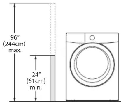
text_image
96" (244cm) max. 24" (61cm) min.
NOTE
Drain hose attached to the washer can reach a 74 in. (188 cm) high standpipe. For higher standpipe, use hose P/N 137098000, available from an authorized parts distributor.
Clearance requirements

IMPORTANT
DO NOT INSTALL YOUR WASHER:
1 In an area exposed to dripping water or outside weather conditions. The ambient temperature should never be below 60°F (15.6°C) to maximize detergent effectiveness.
2 In an area (garage or garage-type building) where gasoline or other fl ammables (including automobiles) are kept or stored.
3 On carpet. Floor MUST be solid with a maximum slope of 1 inch (2.5 cm). To minimize vibration or movement, reinforcement of the floor may be necessary.
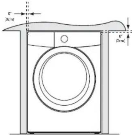
Installation in a Recess or Closet
If washer and dryer are installed in the same closet, door ventilation is required: A minimum of 120 square inches (774.2 cm²) of opening, equally divided at the top and bottom of the door, is required. Louvered openings should be located 3 inches (7.6 cm) from bottom and top of door. Air openings are required to be unobstructed when a door is installed. A louvered door with equivalent air openings for the full length of the door is acceptable.
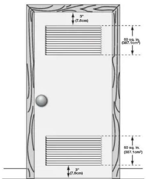
text_image
3" (7.6cm) 60 sq. in. (387.1cm²) 60 sq. in. (387.1cm²) 3" (7.6cm)closet door
| MINIMUM INSTALLATION CLEARANCES - Inches (cm) | ||||
| SIDES REAR TOP FRONT | ||||
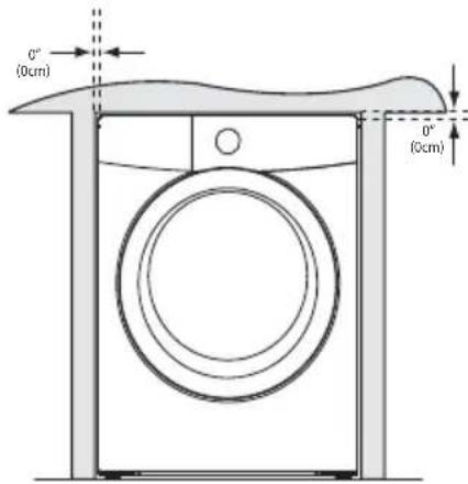
| Alcove 0" (0 cm) 0" (0 cm)* 0" (0 cm) n/a | ||||
| Under-Counter | 0" (0 cm) 0" (0 cm)* 0" (0 cm) n/a | |||
| Closet 0" (0 cm) 0" (0 cm)* 0" (0 cm) 1" (2.5 cm) | ||||
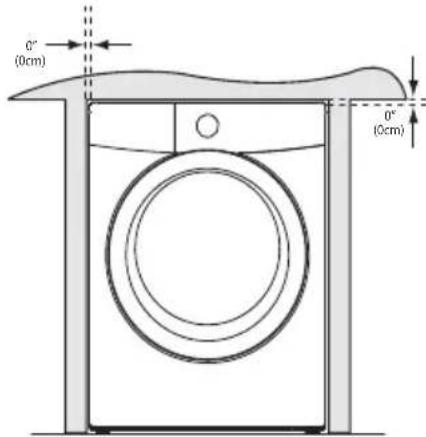
text_image
0° (0cm) 0° (0cm)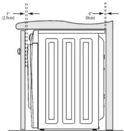
text_image
1° (2.5cm) 0° (0cm)INSTALLATION REQUIREMENTS
Washer Dimensions
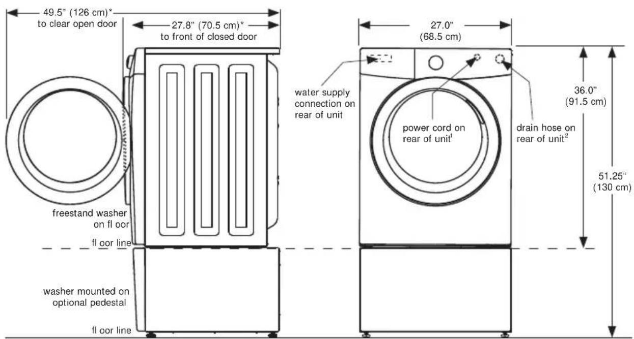
text_image
49.5" (126 cm)* to clear open door 27.8" (70.5 cm)* to front of closed door freestand washer on fl oor fl oor line washer mounted on optional pedestal fl oor line water supply connection on rear of unit power cord on rear of unit¹ drain hose on rear of unit² 27.0" (68.5 cm) 36.0" (91.5 cm) 51.25" (130 cm)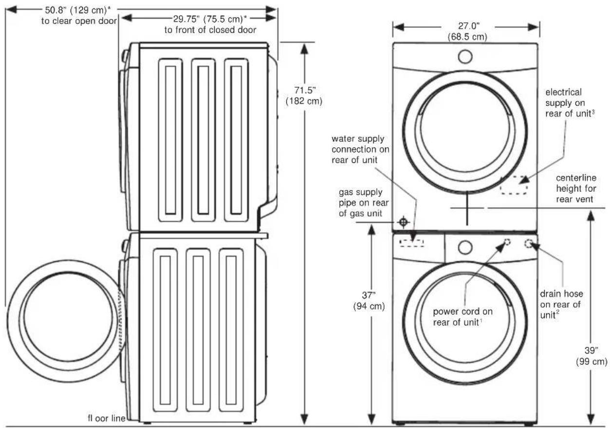
text_image
50.8" (129 cm)* to clear open door 29.75" (75.5 cm)* to front of closed door 71.5" (182 cm) 27.0" (68.5 cm) floor line 37" (94 cm) electrically supply on rear of unit³ water supply connection on rear of unit gas supply pipe on rear of gas unit centerline height for rear vent power cord on rear of unit¹ drain hose on rear of unit² 39" (99 cm)* Connection of water inlet hose on steam dryer adds 3/4 in. (2 cm) to installation depth.
^1 Power supply cord length on washer approximately 60 inches (152.5 cm).
^2 Drain hose length on washer approximately 52 inches (132 cm).
^3 Power supply cord length on gas dryer approximately 60 inches (152.5 cm).
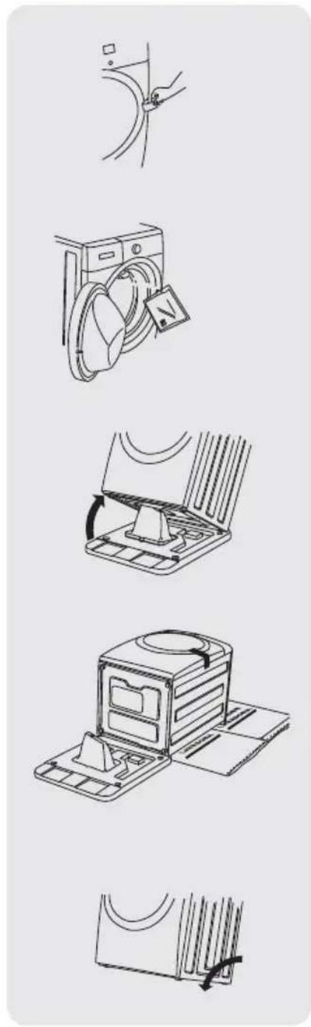
Removing foam packaging

WARNING
SUFFOCATION HAZARD
Destroy the carton and plastic bags after the washer is unpacked. Children might use them for play. Cartons covered with rugs, bedspreads, or plastic sheets can become airtight chambers causing suffocation. Place all materials in a garbage container or make materials inaccessible to children.
1 Temporarily remove door tape.
2 Open washer door and remove everything from the drum.
3 Close door and reapply door tape.
4 Using a rug, blanket or piece of cardboard to protect the floor, carefully lay the washer on it's back.

CAUTION
EXCESSIVE WEIGHT HAZARD
To avoid back or other injury, have more than one person move or lift the washer.
5 Remove styrofoam base and shipping plug and set them aside.
6 Carefully return the washer to an upright position.
7 Carefully move the washer to within 4 feet (1 m) of its final location.

IMPORTANT
Save styrofoam base and shipping plug for use to help prevent washer damage during any future moves.
natural_image
Illustration of five different household appliances and devices, including a washing machine, fan, oven, and storage unit (no text or symbols present)INSTALLATION INSTRUCTIONS
Removing shipping hardware
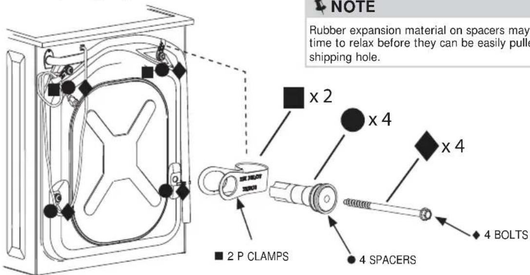
text_image
NOTE Rubber expansion material on spacers may time to relax before they can be easily pulled shipping hole. ■ x 2 x 4 x 4 ■ 2 P CLAMPS 4 SPACERS 4 BOLTSRemove all of the following:
◆ 4 BOLTS
4 SPACERS
2 P CLAMPS
→ IMPORTANT
Save all shipping bolts and spacers for future use. If the washer is to be transported at a later date, the shipping hardware must be reinstalled to help prevent shipping damage.
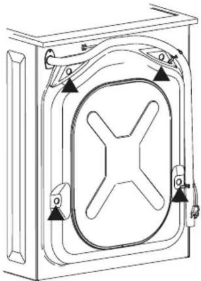
Installing hole plugs
natural_image
Technical line drawing of a mechanical cabinet or enclosure with internal components and mounting brackets (no text or symbols)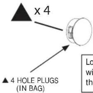
text_image
x 4 ▲ 4 HOLE PLUGS (IN BAG)Locate 4 hole plugs in the small bag supplied with washer instruction guides. Insert them in the holes in washer back panel.
Leveling your washer
Excessive noise and vibration can be prevented by properly leveling the washer.
1 For free standing installation and with the washer within 4 feet (1 m) of its final location, place a level on top of the washer.
2 Use adjustable pliers to adjust the leveling legs so the washer is level front-to-rear and side-to-side, and stable corner-to-corner.
3 Press down on alternate corners and sides and feel for the slightest movement. Adjust the appropriate leg(s) so the washer sits solidly on the floor on ALL four legs. Keep the leveling leg extension at a minimum for best performance of the washer.

NOTE
For pedestal installations, see additional installation instructions included with the pedestal.
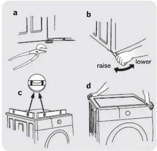
text_image
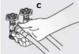
a b raise lower c dConnecting inlet water
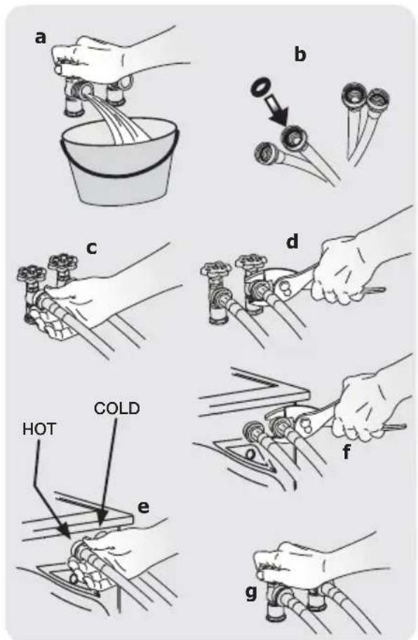
1 Run some water from the hot and cold faucets to flush the water lines and remove particles that might clog the water valve screens and to determine which faucet is hot and which is cold supply.
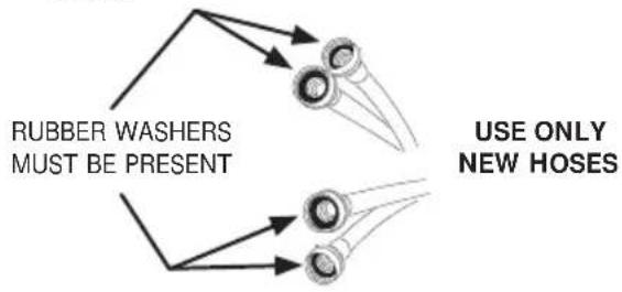
text_image
RUBBER WASHERS MUST BE PRESENT USE ONLY NEW HOSES
NOTE
Hoses are not included with washer purchase. See "Accessories" section for various inlet hose kits to fit your specific installation.
2 Connect the HOT inlet hose to the HOT inlet connection on the washer and the COLD inlet hose to the COLD inlet connection on the washer. Tighten by hand until snug. Then tighten each supply connection another 2/3 turn with pliers. Do not cross thread or over-tighten these connections.
3 Connect the HOT inlet hose to the HOT water supply and the COLD inlet hose to the COLD water supply. Tighten by hand until snug. Then tighten each supply connection another 2/3 turn with pliers. Do not bend, kink or pinch water inlet hoses.
4 Turn on the water and check for leaks.
text_image
a b c d e f g HOT COLDINSTALLATION INSTRUCTIONS
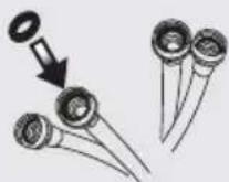
Connecting drain and electrical
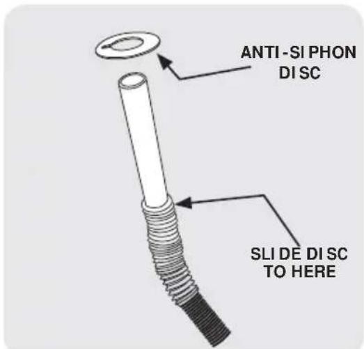
1 Locate the anti-siphon ring shipped with your washer. Place it over the end of the drain hose and slide it past the first ring of "accordion" ribs.
2 Form a "U" shape on the end of the drain hose with the hose pointed toward the drain. Place the formed end in a laundry tub or a standpipe and secure the drain hose with the cable tie (provided in the enclosure package) to the standpipe, inlet hose, laundry tub, etc. so the hose does not pull out from the force of the water.

NOTE
The standpipe inside diameter must be 1-1/4" (3.2 cm) minimum. There must be an air gap around the drain hose in the standpipe. A snug hose fit can cause a siphoning action.

IMPORTANT
Check to ensure the power is off at a circuit breaker/fuse box before plugging the power cord into an outlet.
3 Plug the power cord into a grounded outlet.
text_image
Grounding type wall receptacle Do not, under any circumstances, cut, remove or bypass the grounding prong. Power cord with 3-prong grounded plug4 Turn on the power at a circuit breaker/fuse box.
5 Carefully slide the washer to its final position. Recheck for level and rock corners for stability. Remove and discard door tape.
6 Read the Use & Care Guide provided with the washer. It contains valuable and helpful information that will save you time and money.
7 Run the washer through a complete cycle, checking for water leaks and proper operation.
8 If you have any questions during initial operation, please review the "Service Prevention Checklist" in your Use & Care Guide before calling for service.
9 Place these instructions in a location near the washer for future reference.

NOTE
A wiring diagram and technical data sheet are located under the washer top panel, on top of the detergent dispenser housing.
text_image
ANTI-SI PHON DI SC SLI DE DI SC TO HERE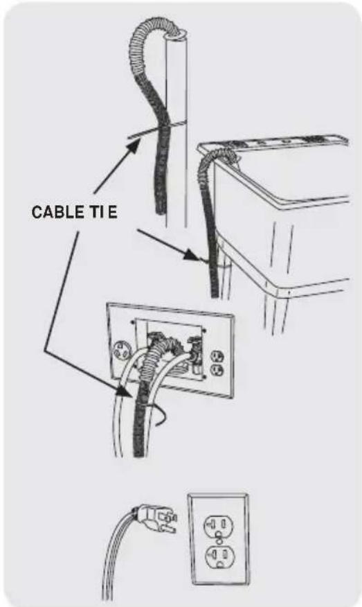
text_image
CABLE TI E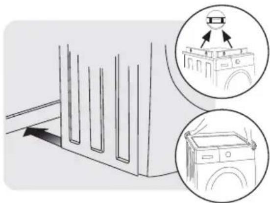
natural_image
Diagram showing a washing machine with two circular insets illustrating the exterior view and front view (no text or symbols present)MATCHING STORAGE PEDESTAL\*
Classic White Pedestal - P/N CFPWD15W Classic Silver Pedestal - P/N CFPWD15A
A storage pedestal accessory, specifically designed for this washer may be used to elevate the washer for ease of use. This pedestal will add about 15" (38 cm) to the height of your unit for a total height of 51.25" (130 cm). *Other colors may be available. Contact the source where you purchased your washer.
DRYER STACKING KIT
P/N STACKIT4X
Depending on the model you purchased, a kit for stacking a matching dryer on top of this washer may have been included in the initial purchase of your dryer. If your model did not include a stacking kit or you desire another stacking kit, you may order one.
INLET HOSE KITS
Please call 866-233-8353 (in Canada, 800-265-8352) to explore hose kit options that will meet your specific installation needs.
DRAIN HOSE EXTENSION KIT
P/N 137098000
In order to reach standpipe heights or distances beyond the reach of the drain hose supplied, order the DRAIN HOSE EXTENSION KIT.
MOBILE HOME INSTALLATION KIT
P/N 137067200
Installation in a mobile home requires the use of a MOBILE HOME INSTALLATION KIT.
UNIVERSAL APPLIANCE WRENCH
P/N 137019200
A UNIVERSAL APPLIANCE WRENCH is available to aid in dryer/washer/pedestal feet adjustment.
TOUCH UP PAINT PENS\*
Classic White Touch Up Pen - P/N 5304468812
Classic Silver Touch Up Pen - P/N 5304471228
*Other colors may be available. Contact the source where you purchased your washer.
CAUTION
Failure to use accessories manufactured by (or approved by) the manufacturer could result in personal injury, property damage or damage to the washer.
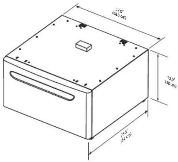
text_image
27.0° (68,5 cm) 15.0° (38 cm) 26.5° (67 cm)
Replacement parts:
If replacements parts are needed for your washer, contact the source where you purchased your washer or refer to your Use and Care Guide for more information.
WARNING
ELECTRICAL SHOCK HAZARD
Label all wires prior to disconnection when servicing controls. Wiring errors can cause improper and dangerous operation. Verify proper operation after servicing.
NOTES
Tout à propos de
Installation
de votre Laveuse

natural_image
Silhouette illustration of various household appliances including washing machines, refrigerators, and a refrigerator (no text or symbols)TABLE DES MATIÈRES
text_image
3" (7.6cm) 60 sq. in. (387.1cm²) 3" (7.6cm) 60 sq. in. (387.1cm²)Porte de placard
| DÉGAGEMENTS MINIMAUX - Centimètres (pouces) | ||||
| CÔTÉS ARRIÈRE DESSUS | AVANT | |||
| Alcôve 0 cm | (0 po) 0 cm (0 | po) 0 cm (0 po) s. o. | ||
| Sous le comptoir | 0 cm (0 po) 0 | cm (0 po) 0 cm (0 po) s. o. | ||
| Placard 0 cm | (0 po) 0 cm (0 | po) 0 cm (0 po) 2,5 cm (1 po) | ||
text_image
0° (0cm) 0° (0cm)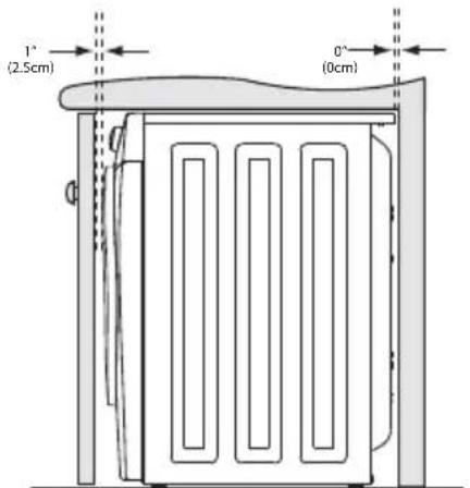
text_image
1° (2.5cm) 0° (0cm)natural_image
Illustration of five different household appliances and devices, including a washing machine, fan, oven, and storage unit (no text or symbols present)INSTRUCTIONS D'INSTALLATION
natural_image
Technical line drawing of a cabinet or enclosure with internal components and mounting brackets (no text or symbols)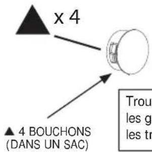
text_image
x 4 ▲ 4 BOUCHONS (DANS UN SAC) Trou- les gr les trnatural_image
Illustration of a hand washing noodles into a bowl (no text or symbols)b
natural_image
Illustration of a hand holding a pipe with two valves (no text or symbols)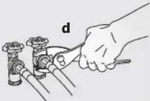
natural_image
Illustration of a hand using a tool to adjust or install a pipe fitting (no text or symbols present)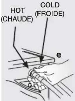
text_image
HOT (CHAUDE) COLD (FROIDE) e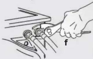
natural_image
Illustration of a hand using a tool to adjust or install components on a vehicle (no text or symbols visible)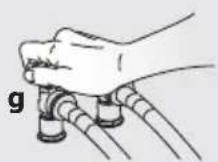

REMARQUE
natural_image
Diagram showing a washing machine with two circular insets illustrating the components of the front panel (no text or symbols present)SOCLE DE RANGEMENT ASSORTI \*
Socle Blanc -PIÈCE N° CFPWD15W
text_image
27.0° (68,5 cm) 15.0° (38 cm) 26.5° (67 cm)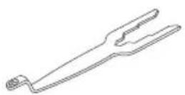
natural_image
Silhouette illustration of various household appliances including washing machines, refrigerators, and a refrigerator (no text or symbols)ÍNDICE
text_image
3" (7.6cm) 60 sq. in. (387.1cm²) 3" (7.6cm) 60 sq. in. (387.1cm²)puerta del armario
| ESPACIOS MÍNIMOS PARA LA INSTALACIÓN: cm (pulgadas) | ||||
| LATERALES | PARTE TRASERA | PARTE SUPERIOR | PARTE DELANTERA | |
| Hueco 0 cm (0") 0 cm (0") | 0 cm (0") n/d | |||
| Debajo de la encimera | 0 cm (0") 0 | cm (0") 0 cm (0") n/d | ||
| Armario 0 cm (0") 0 cm (0") 0 cm (0") | 2,5 cm (1") | |||
text_image
0° (0cm) 0° (0cm)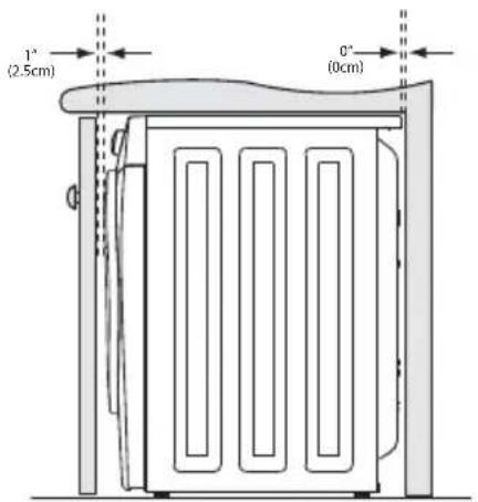
text_image
1" (2.5cm) 0" (0cm)natural_image
Illustration of five different household appliances and tools, including a washing machine, fan switch, oven, and storage unit (no text or symbols present)natural_image
Technical line drawing of a mechanical cabinet or enclosure with internal components and mounting brackets (no text or symbols)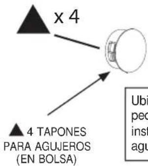
text_image
x 4 4 TAPONES PARA AGUJEROS (EN BOLSA) Ubip pec inst agunatural_image
Diagram showing a washing machine with two circular insets illustrating the exterior view and front view (no text or symbols present)PEDESTAL DE ALMACENAMI ENTO CONCORDANTE\*
Pedestal de color blanco - P/N CFPWD15W
Pedestal de color plateada - P/N CFPWD15A
text_image
27.0" (68.5 cm) 15.0" (38 cm) 36.5" (67 cm)