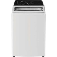
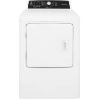
FLVW7523WH - Washing machine FRIGIDAIRE - Free user manual and instructions
Find the device manual for free FLVW7523WH FRIGIDAIRE in PDF.


| Product Type | Front-loading washing machine |
| Brand | Frigidaire |
| Model | FLVW7523WH |
| Dimensions (H x W x D) | 93 x 68.5 x 72.5 cm (with door closed), 145.7 cm (door open) |
| Net weight | Approximately 65 kg |
| Power supply | 120 V ~ 60 Hz, 15 A, grounded outlet |
| Water pressure required | 206.8 to 827.4 kPa (30-120 psi) |
| Washing capacity | 7.5 kg (approximate) |
| Maximum spin speed | 1200 rpm (estimated) |
| Wash programs | Cotton, synthetics, delicates, rinse, spin, etc. |
| Available temperatures | Cold, warm, hot |
| Noise level (wash/spin) | Approximately 55/72 dB(A) |
| Water consumption per cycle | Approximately 60 liters |
| Annual energy consumption | Approximately 180 kWh (estimated) |
| Child safety | Key lock function (assumed) |
| Leak protection | Not specified |
| Tub material | Stainless steel (assumed) |
| Water inlet hose length | Approximately 1.5 m (not included) |
| Drain hose length | Approximately 1.7 m |
| Power cord length | Approximately 1.85 m |
| Included accessories | Universal wrench, white touch-up pen, hose clamps |
Frequently Asked Questions - FLVW7523WH FRIGIDAIRE
If the problem persists, contact customer service.
The white touch-up pen is referenced under number 5304468812.
User questions about FLVW7523WH FRIGIDAIRE
0 question about this device. Answer the ones you know or ask your own.
Ask a new question about this device
Download the instructions for your Washing machine in PDF format for free! Find your manual FLVW7523WH - FRIGIDAIRE and take your electronic device back in hand. On this page are published all the documents necessary for the use of your device. FLVW7523WH by FRIGIDAIRE.
USER MANUAL FLVW7523WH FRIGIDAIRE
All about the Installation of your Washer
Important Safety Instructions 2-3
Installation Requirements 4-6
Installation Instructions 78
Accessories.... 9
Français ...... 0
Español 19
A28709101 (August 2024)

WARNING
Please read all instructions before using this washer.
Recognize safety symbols, words and labels
Safety items throughout this manual are labeled with a WARNING or CAUTION based on the risk type as described below:
Definitions
This is the safety alert symbol. It is used to alert you to potential personal injury hazards. Obey all safety messages that follow this symbol to avoid possible injury or death.

DANGER
DANGER indicates an imminently hazardous situation which, if not avoided, will result in death or serious injury.

WARNING
WARNING indicates a potentially hazardous situation which, if not avoided, could result in death or serious injury.

CAUTION
CAUTION indicates a potentially hazardous situation which, if not avoided, may result in minor or moderate injury.

IMPORTANT
IMPORTANT indicates installation, operation or maintenance information which is important but not hazard-related.

Installation Checklist
Leveling
☐ Washer is level, side-to-side and front-to-back
□ Cabinet is setting solid on all corners
Water Supply
☐ Use only new hoses and verify rubber sealing washers are installed
☐ HOT supply is connected to HOT inlet and COLD supply is connected to COLD inlet
☐ HOT and COLD water supply turned on
☐ No leaks present at water supply connections or appliance inlet connections - recheck in 24 hours
Drain
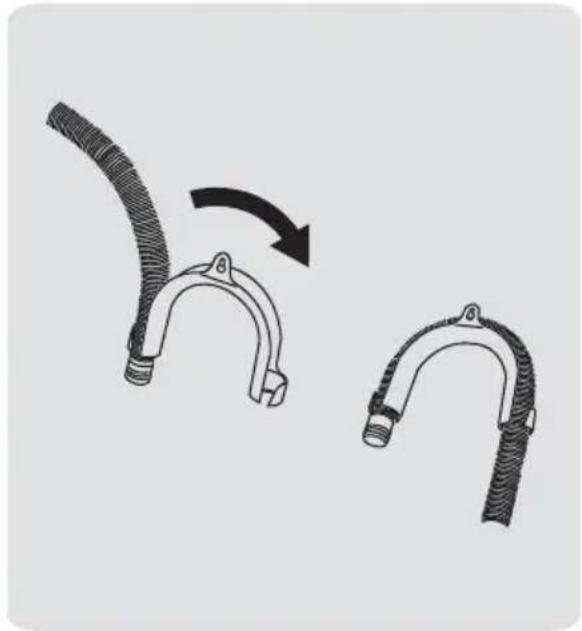
☐ Drain hose snapped in "U" channel (shipped in drum)
☐ Stand pipe or wall drain height minimum 39"
☐ Drain hose secured in place with cable tie (shipped in tub)
Electrical Power
□ House power turned on
□ Washer plugged in
Final Checks
☐ Installation Instructions and Use and Care Guide read thoroughly
☐ Water enters tub when cycle starts with lid lowered.
□ Registration card sent in
IMPORTANT SAFETY INSTRUCTIONS

NOTE
The electrical service to the washer must conform with local codes and ordinances and the latest edition of the National Electrical Code, ANSI/NFPA 70, or in Canada, the Canadian Electrical Code C22.1 part 1.

WARNING
SUFFOCATION HAZARD
Destroy the carton and plastic bags after the washer is unpacked. Children might use them for play. Cartons covered with rugs, bedspreads, or plastic sheets can become airtight chambers causing suffocation. Place all materials in a garbage container or make materials inaccessible to children.

CAUTION
EXCESSIVE WEIGHT HAZARD
To avoid back or other injury, have more than one person move or lift the washer.

WARNING
FIRE HAZARD
For your safety the information in this manual must be followed to minimize the risk of fire or explosion or to prevent property damage, personal injury or loss of life. Do not store or use gasoline or other flammable vapors and liquids in the vicinity of this or any other appliance.

IMPORTANT
The instructions in this manual and all other literature included with this washer are not meant to cover every possible condition and situation that may occur. Good safe practice and caution MUST be applied when installing, operating and maintaining any appliance.
Maximum benefits and enjoyment are achieved when all the Safety and Operating Instructions are understood and practiced as a routine with your laundering tasks.
Save these instructions for future reference.
Tools and materials needed for installation:
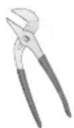
Adjustable pliers
AND
natural_image
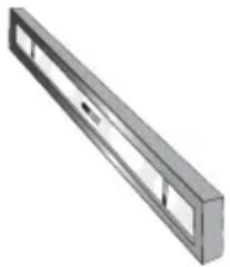
3D rendering of a rectangular metal bracket with internal cutouts (no text or symbols)Carpenter's level
natural_image
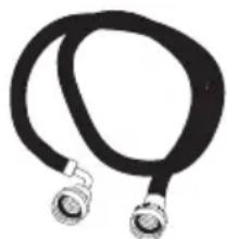
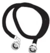
Coiled black cable with two metallic connectors (no text or symbols visible)Inlet hose (x2)

NOTE
Hoses are not included with washer purchase. See "Accessories" section for various inlet hose kits to fit your specific installation.
INSTALLATION REQUIREMENTS
Electrical system requirements
CIRCUIT - Individual, properly polarized and grounded 15 amp. branch circuit fused with 15 amp. time delay fuse or circuit breaker.
POWER SUPPLY - 2 wire, with ground, 120 volt single phase, 60 Hz, Alternating Current.
NOTE
Because of potentially inconsistent voltage capabilities, the use of this washer with power created by gas powered generators, solar powered generators, wind powered generators or any other generator other than the local utility company is not recommended.
OUTLET RECEPTACLE - Properly grounded 3-prong receptacle to be located so the power supply cord is accessible when the washer is in an installed position.
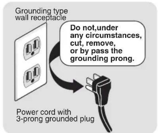
NOTE
GFI (Ground Fault Interrupter) receptacle is not required.
Ground requirements
WARNING
ELECTRICAL SHOCK HAZARD
Improper connection of the equipment grounding conductor can result in a risk of electrical shock. Check with a licensed electrician if you are in doubt as to whether the appliance is properly grounded.
The electrical valve, retractor, motor and drain pump of this appliance are intentionally not grounded and may present a risk of electric shock during serving. Do not contact these electronic devices while the appliance is energized.
1 The washer MUST be grounded. In the event of malfunction or breakdown, grounding will reduce the risk of electrical shock by a path of least resistance for electrical current.
2 Since your washer is equipped with a power supply cord having an equipment-grounding conductor and a grounding plug, the plug MUST be plugged into an appropriate, copper wired receptacle that is properly installed and grounded in accordance with all local codes and ordinances or in the absence of local codes, with the National Electrical Codes, ANSI/NFPA 70 (latest edition). If in doubt, call a licensed electrician. DO NOT cut off or alter the grounding prong on the power supply cord. In situations where a two-slot receptacle is present, it is the owner's responsibility to have a licensed electrician replace it with a properly grounded three prong grounding type receptacle.
Water supply requirements
Hot and cold water faucets MUST be 3/4 inch with threading for laundry hose connection. Water pressure MUST be between 30 and 116 psi. Pressure difference between hot and cold cannot be more than 10 psi. Your water department can advise you of your water pressure.
INSTALLATION REQUIREMENTS
Drain system requirements
1 Drain capable of eliminating 17 gals (64.3 L) per minute.
2 A standpipe diameter of 1-1/4 in. (3.18 cm) minimum.
3 The standpipe height above the floor should be:
Minimum height: 39 in. (99 cm)
Maximum height: 96 in. (244 cm)

NOTE
For installations requiring a longer drain hose, have a qualified technician install a longer drain hose (according to your model number) available from an authorized parts distributor. For drain systems in the floor, install a syphon break kit available from your local hardware store.
Installation in a Recess or Closet
If washer and dryer are installed in the same closet, door ventilation is required: A minimum of 120 square inches (774.2 cm ^2 ) of opening, equally divided at the top and bottom of the door, is required. Louvered openings should be located 3 inches (7.6 cm) from bottom and top of door. Air openings are required to be unobstructed when a door is installed. A louvered door with equivalent air openings for the full length of the door is acceptable.
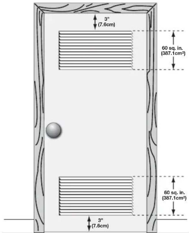
closet door
INSTALLATION REQUIREMENTS
Clearance requirements

IMPORTANT
DO NOT INSTALL YOUR WASHER:
1 In an area exposed to dripping water or outside weather conditions. The ambient temperature should never be below 60° F (15.6° C) to maximize detergent effectiveness.
2 In an area (garage or garage-type building) where gasoline or other flammables (including automobiles) are kept or stored.
3 On carpet. Floor MUST be solid with a maximum slope of 1 inch (2.5 cm). To minimize vibration or movement, reinforcement of the floor may be necessary.
| MINIMUM INSTALLATION CLEARANCES - Inches (cm) | ||||
| SIDES REAR TOP FRONT | ||||
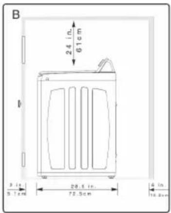
| Alcove | 1"(2.5 cm) | 6"(15.2 cm) | 24"(61 cm) | n/a |
| Closet | 1"(2.5 cm) | 6"(15.2 cm) | 24"(61 cm) | 2"(5.1 cm) |
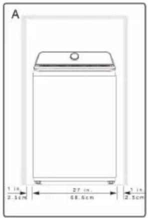
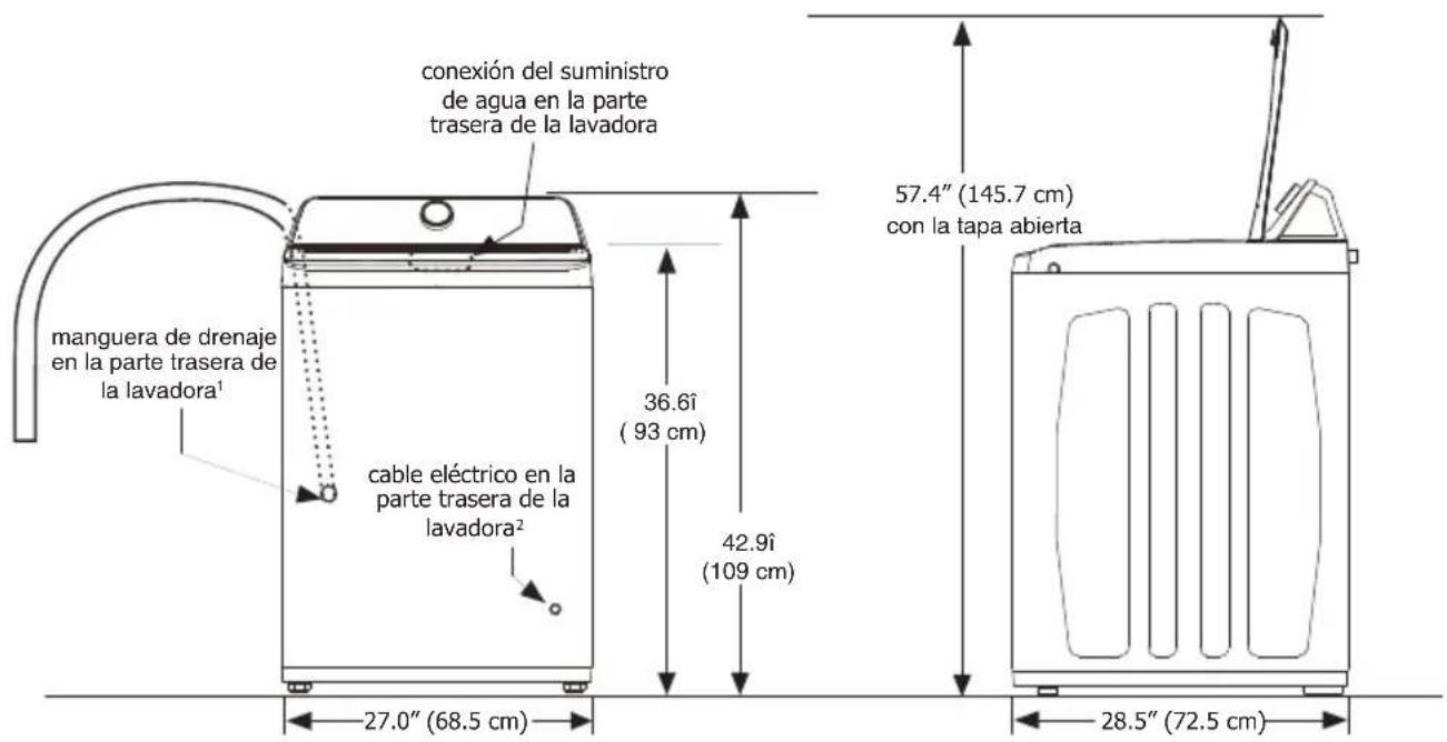
Washer Dimensions
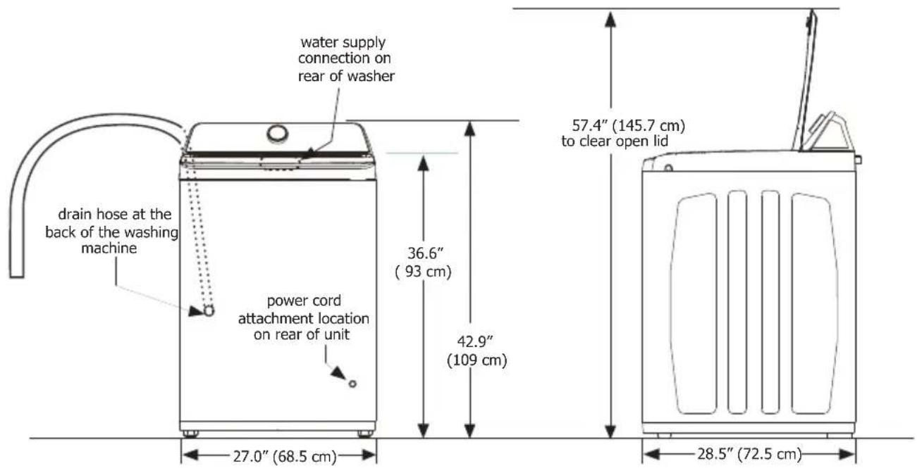
^1 Drain hose length on washer approximately 66.93 inches (170 cm).
^2 Power supply cord length approximately 72.8 inches (185 cm).
Leveling your washer
Excessive noise and vibration can be prevented by properly leveling the washer.
1 With the washer within 4 feet (1 m) of its final location, use a carpenter's level to level your washer front-to-back and side-to-side. For front-to-back leveling, place edge of the level flush to the front panel. For side-to-side leveling place the edge of the level flush to the side panel.
2 Use adjustable pliers to adjust the front leveling legs so the washer is level front-to-rear and side-to-side, and stable corner-to-corner.
3 Press down on alternate corners and sides and feel for the slightest movement. Adjust the appropriate front leg(s) so the washer sits solidly on the floor on ALL four legs. Keep the leveling leg extension at a minimum for best performance of the washer.
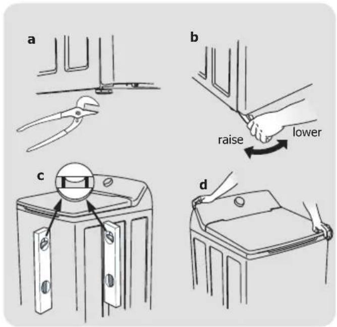
Connecting inlet water
1 Run some water from the hot and cold faucets to flush the water lines and remove particles that might clog the water valve screens and to determine which faucet is hot and which is cold supply.
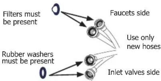
flowchart
graph TD
    A["Filters must be present"] --> B["Faucets side"]
    C["Rubber washers must be present"] --> D["Inlet valves side"]
    B --> E["Use only new hoses"]
    D --> E
NOTE
Hoses are not included with washer purchase. See "Accessories" section for various inlet hose kits to fit your specific installation.
2 Connect the HOT inlet hose to the HOT inlet connection on the washer and the COLD inlet hose to the COLD inlet connection on the washer. Tighten by hand until snug. Then tighten each supply connection another 2/3 turn with pliers. Do not cross thread or over-tighten these connections.
3 Connect the HOT inlet hose to the HOT water supply and the COLD inlet hose to the COLD water supply. Tighten by hand until snug. Then tighten each supply connection another 2/3 turn with pliers. Do not bend, kink or pinch water inlet hoses.
4 Turn on the water and check for leaks.
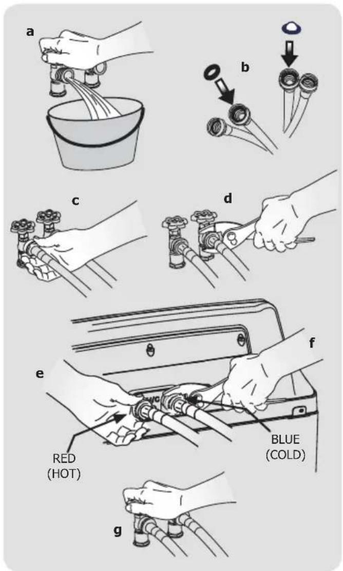
INSTALLATION INSTRUCTIONS
Connecting drain and electrical
1 Place the hook end of the drain hose in the drain opening. Secure the drain hose with the cable tie (provided in the enclosure package) to the standpipe, inlet hose, laundry tub, etc. so the hose does not pull out from the force of the water.
NOTE
The standpipe inside diameter must be 1-1/4" (3.2 cm) minimum. There must be an air gap around the drain hose in the standpipe. A snug hose fit can cause a siphoning action.

IMPORTANT
Check to ensure the power is off at a circuit breaker/fuse box before plugging the power cord into an outlet.
3 Plug the power cord into a grounded outlet.
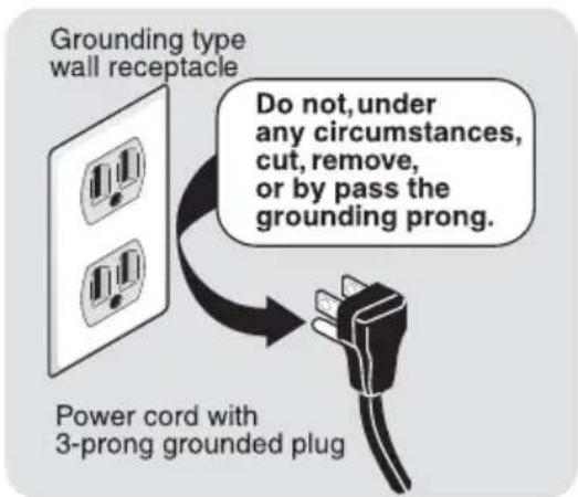
4 Turn on the power at the circuit breaker/fuse box.
5 Carefully slide the washer to its final position. Recheck for level and rock corners for stability.
6 Read the Use & Care Guide provided with the washer. It contains valuable and helpful information that will save you time and money.
7 Run the washer through a complete cycle, checking for water leaks and proper operation.
8 If you have any questions during initial operation, please review the "Avoid Service Checklist" in your Use & Care Guide before calling for service.
9 Place these instructions in a location near the appliance for future reference.
natural_image
Diagram showing two curved pipe fittings with a directional arrow indicating movement (no text or symbols)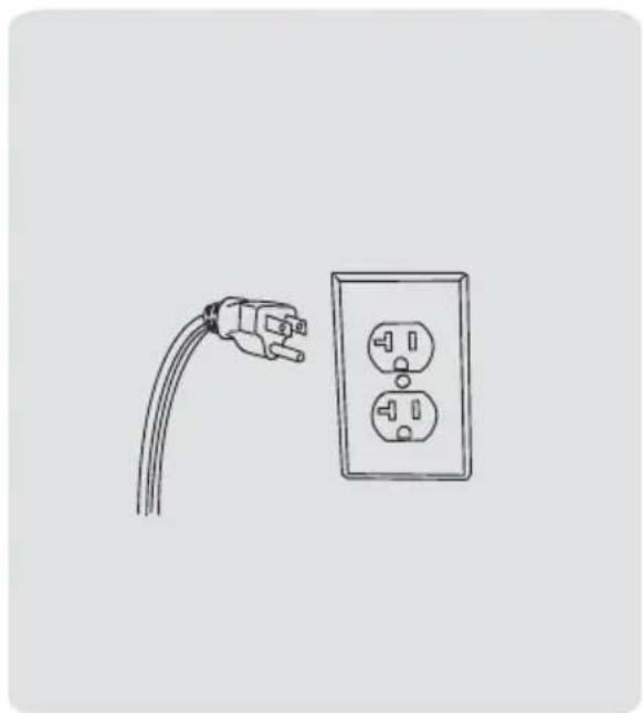
natural_image
Line drawing of a power outlet with two socket plugs connected to a terminal plug (no text or symbols)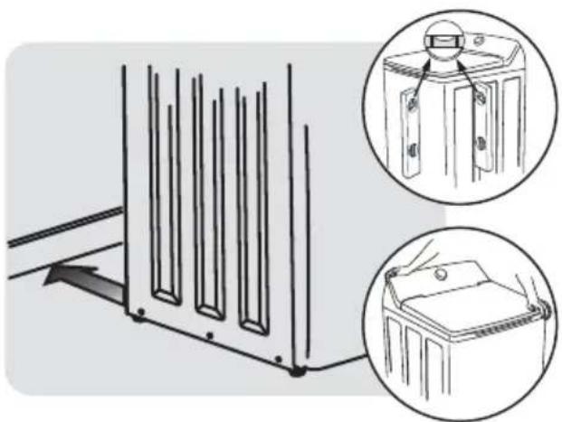
natural_image
Diagram showing a mechanical assembly with two views of a device, one with a magnified inset (no text or symbols)INLET HOSE KITS
Please call 866-233-8353 (in Canada, 800-265-8352) to explore hose kit options that will meet your speci c installation needs.
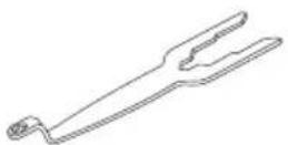
UNIVERSAL APPLIANCE WRENCH
P/N 137019200
A UNIVERSAL APPLIANCE WRENCH is available to aid in dryer/washer feet adjustment.
TOUCH UP PAINT PENS\*
Classic White Touch Up Pen - P/N 5304468812
*Other colors may be available. Contact the source where you purchased your washer.
CAUTION
Failure to use accessories manufactured by (or approved by) the manufacturer could result in personal injury, property damage or damage to the washer.
Replacement parts:
If replacements parts are needed for your washer, contact the source where you purchased your washer or refer to your Use and Care Guide for more information.
WARNING
ELECTRICAL SHOCK HAZARD
Label all wires prior to disconnection when servicing controls. Wiring errors can cause improper and dangerous operation. Verify proper operation after servicing.
natural_image
3D rendering of a rectangular metal bracket with internal cutouts (no text or symbols)natural_image
Coiled black cable with two metallic connectors (no text or symbols visible)Porte de placard
natural_image
Diagram showing two curved pipe fittings with a directional arrow indicating movement (no text or symbols)natural_image
Illustration of a power plug and its corresponding socket (no text or symbols)natural_image
Diagram showing a mechanical component with two views of its side, one with a magnified inset (no text or symbols)ACCESSOI RES
KITS TUYAUX D'ALIMENTATION
A28709101 (August 2024)
natural_image
3D rendering of a rectangular metal bracket with internal cutouts and mounting holes (no text or symbols)Nivel de carpintero
natural_image
Coiled black cable with two metallic connectors (no text or symbols visible)Inlet hose (x2)

NOTA
puerta del armario
Dimensiones de Lavadora
natural_image
Diagram showing two curved mechanical components with a directional arrow indicating transformation (no text or symbols)natural_image
Simple line drawing of a plug and two electrical outlets (no text or symbols)natural_image
Diagram showing a mechanical component with two views of its internal structure, no text or symbols present.KITS DE MANGUERAS LLENADO
Our home is your home. Visit us if you need help with any of these things:

owner support

accessories

service

registration
(See your registration card for more information.)
Frigidaire.com
1-800-374-4432
Frigidaire.ca
1-800-265-8352



- All about the Installation of your Washer
- WARNING
- Recognize safety symbols, words and labels
- Definitions
- DANGER
- CAUTION
- IMPORTANT
- Installation Checklist
- Leveling
- Water Supply
- Drain
- Electrical Power
- Final Checks
- IMPORTANT SAFETY INSTRUCTIONS
- NOTE
- SUFFOCATION HAZARD
- EXCESSIVE WEIGHT HAZARD
- FIRE HAZARD
- Save these instructions for future reference.
- Tools and materials needed for installation:
- INSTALLATION REQUIREMENTS
- Electrical system requirements
- Ground requirements
- ELECTRICAL SHOCK HAZARD
- Water supply requirements
- Drain system requirements
- Installation in a Recess or Closet
- Clearance requirements
- DO NOT INSTALL YOUR WASHER:
- Washer Dimensions
- Leveling your washer
- Connecting inlet water
- INSTALLATION INSTRUCTIONS
- Connecting drain and electrical
- INLET HOSE KITS
- UNIVERSAL APPLIANCE WRENCH
- TOUCH UP PAINT PENS\*
- Replacement parts:
- ACCESSOI RES
- KITS TUYAUX D'ALIMENTATION
- NOTA
- Dimensiones de Lavadora
- KITS DE MANGUERAS LLENADO
Brand : FRIGIDAIRE
Model : FLVW7523WH
Category : Washing machine