S3M30KXNIB - Inverter Tripp Lite - Free user manual and instructions
Find the device manual for free S3M30KXNIB Tripp Lite in PDF.

User questions about S3M30KXNIB Tripp Lite
0 question about this device. Answer the ones you know or ask your own.
Ask a new question about this device
Download the instructions for your Inverter in PDF format for free! Find your manual S3M30KXNIB - Tripp Lite and take your electronic device back in hand. On this page are published all the documents necessary for the use of your device. S3M30KXNIB by Tripp Lite.
USER MANUAL S3M30KXNIB Tripp Lite
Models: S3M30KX, S3M30KX-NIB, S3M40KX, S3M40KX-NIB, S3M60KX, S3M80KX
Input: 220/230/240V (Ph-N), 380/400/415V (Ph-Ph), 30 4-Wire + PE


Table of Contents
1. Introduction 3
2. Important SafetyWarnings 4
2.1 UPS LocationWarnings 4
2.2 Equipment Connection Warnings 4
2.3 BatteryWarnings 4
2.4 Transportation and Storage 5
2.5 Preparation 5
2.6 Installation 5
2.7 ConnectionWarnings 5
2.8 Operation 6
2.9 Standards
6
3. Installation and Setup 7
3.1 Unpacking and Inspection 7
3.2 Internal Battery Connection Procedure for S3M30KX, 9 S3M40KIX, S3M60KX and S3M80KX Models
3.3 Installation of Internal Batteries in S3M30KX-NIB 10 and S3M40KX-NIB Models
3.4 Single UPS Installation 22
3.5UPS Installation for Parallel Systems 24
3.6 External Battery Connection 25
4. Operation 26
4.1 Display Button Operation 26
4.2 LED Indicators and LCD Panel 26
4.3 Audible Alarm 28
4.4 Single UPS Operation 28
4.5 ParallelUPSOperation 30
4.6 LCD Panel Abbreviations 32
4.7 Setup Menu 32
4.8 Operating Mode/Status Description 38
4.9 Fault Codes 44
4.10 Warning Indicator 45
4.11 Warning Code 45
5. Communication 46
5.1 SNMP Monitoring Slot 46
5.2 EPO Connector 46
5.3 RS-232 Port 46
5.4 USB Port 46
6.Troubleshooting 47
7. Storage and Maintenance 48
7.1 Storage 48
7.2 Maintenance 48
7.3 Battery 48
7.4 Fan 48
8. Specifications 49
9.Warranty 52
Espanol 53
Français 105
Pycckn 157
Deutsch 209
1. Introduction
Tripp Lite's SmartOnline S3MKX-Series Uninterruptible Power Supply (UPS) is a Voltage and Frequency Independent (VFI) true on-line, double-conversion 3-phase UPS system. This UPS continuously conditions the incoming electrical power supply, eliminating power disturbances that will otherwise damage sensitive electronic devices and minimizing system downtime from power fluctuations and interruptions.
S3MKX-Series UPS systems are designed to the highest quality and performance standards and offer the following features:
| Model Agency Number | Capacity | |
| S3M30KX AG-6030 30kVA | ||
| S3M30KX -NIB | AG-6031 | 30kVA |
| S3M40KX AG-6040 40kVA | ||
| S3M40KX -NIB | AG-6041 | 40kVA |
| S3M60KX AG-6060 60kVA | ||
| S3M80KX AG-6080 80kVA | ||
True on-line UPS - the highest level of UPS protection, fully regulates the incoming power with zero transfer time to battery in the event of an extended mains failure so critical loads remain continuously supported
- Paralleling for capacity of up to three UPS systems
- High-efficiency performance in AC On-line and Battery Standby Modes minimise energy consumption
- Market-leading compact footprint, so more power can be provided from smaller spaces
- ECO Mode allows the UPS to operate on bypass in stable utility conditions and immediately transfers to inverter to support the load when the utility input drops below tolerance
- High output power factor - more actual power allows more equipment to be supported
Automatic and manual bypass increase system reliability and allow for maintenance without removing power from the attached load
- Wide input voltage window - the UPS system regulates even poor-quality incoming power without reverting to battery, maximising system uptime and protecting battery life
- Matching external battery cabinets allow for increased battery autonomy
Emergency shutdown via REPO
SNMP Network Monitoring and Control and Contact-Closure Management cards available
SmartOnline S3MKX-Series UPS systems are ideally suited for protecting the following mission-critical electrical applications:
IT infrastructure
Telecommunications
Networks (LAN/WAN)
Corporate infrastructure
- Security and emergency systems
Light industrial applications
Financial institutions
2. Important SafetyWarnings
SAVE THESE INSTRUCTIONS
This manual contains important instructions and warnings that should be followed during the installation and maintenance of all Tripp Lite SmartOnline S3MX 3-Phase 30kVA, 40kVA, 60kVA and 80kVA UPS Systems and their batteries. Failure to heed these warnings may affect your warranty.
2.1 UPS LocationWarnings
Install the UPS indoors, away from heat, direct sunlight, dust and excess moisture or other conductive contaminants.
- Install the UPS in a structurally sound area. The UPS is extremely heavy; take care when moving and lifting the unit.
- Only operate the UPS at indoor temperatures between 0^ C and 40^ C.
- Optimum UPS performance and maximum battery life is obtained when the operating temperature is maintained between 17^ and 25^ .
- Ensure the installation area has sufficient space for maintenance and ventilation of the UPS system. Maintain a minimum clearance of 50~cm from the rear, front and both sides of the UPS for maintenance and ventilation.
- Do not install the UPS near magnetic storage media, as this may result in data corruption.
2.2 Equipment ConnectionWarnings
- Use of this equipment in life support applications where failure of this equipment can reasonably be expected to cause the failure of the life support equipment or to significantly affect its safety or effectiveness is not recommended.
- The UPS system contains its own energy source (battery). The output terminals may be live even when the UPS is not connected to an AC supply.
2.3 BatteryWarnings
This UPS contains LETHAL VOLTAGES. The UPS is designed to supply power, even when disconnected from utility power. Only AUTHORISED SERVICE PERSONNEL should access the interior of the UPS after disconnecting utility and DC power.
Batteries present a risk of electrical shock and burns from high short-circuit current. Battery connection or replacement should be performed only by qualified service personnel, observing proper precautions. Turn off the UPS before connecting or disconnecting internal batteries. Use tools with insulated handles. Do not open the batteries. Do not short or bridge the battery terminals with any object.
- The batteries are recyclable. Refer to local codes for disposal requirements or visit http://www.triplite.com/support/recycling-program for recycling information.
- Do not dispose of the batteries in a fire, mutilate the batteries or open the battery coverings. Escaping electrolytes may be toxic and cause injury to skin and eyes.
- Do not disconnect the batteries while the UPS is in battery mode.
- Disconnect the charging source prior to connecting or disconnecting terminals.
The following precautions should be observed:
1) Remove watches, rings and other metal objects.
2) Use tools with insulated handles.
3) Wear rubber gloves and electrical-grade boots.
4) Use an electrical-grade rubber mat while servicing batteries.
5) Do not lay tools or metal parts on top of batteries or battery cabinets.
6) Determine whether the battery supply (+, -, N) is inadvertently grounded. If it is, remove the source of the ground. Contact with any part of a grounded battery can result in electric shock. The likelihood of an electric shock is reduced if such grounds are removed during installation and maintenance.
- Battery replacement should be performed only by authorised service personnel, using the same number and type of batteries (sealed lead acid).

WARNING: In order to avoid any hazardous conditions during UPS installation and maintenance, these tasks may be performed only by qualified and experienced electricians.
Please read this Owner's Manual and the safety instructions carefully before installing or using the unit.
2. Important SafetyWarnings
2.4 Transportation and Storage
To protect against shock and impact, transport the UPS system only in the original packaging.
The UPS must be stored in a room that is dry and ventilated.
2.5 Preparation
Condensation may occur if the UPS system is moved directly from a cold to a warm environment. The UPS system must be completely dry before being installed. Please allow at least two hours for the UPS system to adjust to the environment.
Do not install the UPS system near water or in moist environments.
Do not install the UPS system in direct sunlight or near heat sources.
Do not block the ventilation holes on the UPS system's housing.
2.6 Installation
Do not connect appliances or devices that could overload the UPS (i.e., equipment with large electrical motors) to the UPS output sockets or terminal.
Carefully arrange cables so no one can step on or trip over them.
Do not block the UPS system's air vents. The UPS must be installed in a location with good ventilation. Ensure adequate ventilation space on each side of the unit.
The UPS contains an earthed terminal. In the final installed system configuration, ensure equipotential earth grounding to the external UPS battery cabinet by connecting the earth terminals of both cabinets together.
The UPS should only be installed by qualified maintenance electrical service personnel.
An appropriate disconnect device such as short-circuit backup protection must be provided in the building wiring installation.
An integral single-emergency switching device should be included in the building wiring installation.
Connect the earth ground before connecting to the building wiring terminal.
Installation and wiring must be performed in accordance with local electrical codes and regulations.
2.7 ConnectionWarnings
The UPS system does not contain standard backfeed protection inside. Isolate the UPS before working on this circuit. The isolation device must be able to carry the UPS input current.
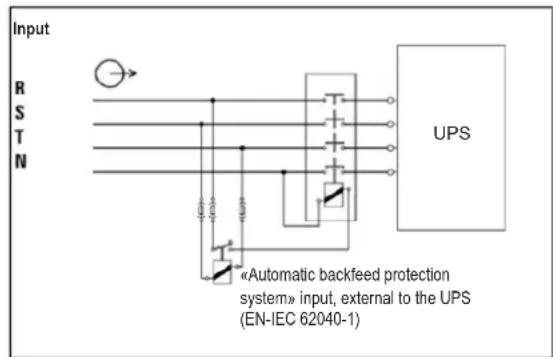
- This UPS should be connected with TN earthing system.
- The power supply for this unit must be 3-phase rated in accordance with the equipment nameplate. It also must be suitably grounded.
- The input power to 3-phase UPS models requires a 4-pole breaker.
- Use of this equipment in life support applications where failure of this equipment can reasonably be expected to cause the failure of the life support equipment or to significantly affect its safety or effectiveness is not recommended.
- Connect the UPS power module's grounding terminal to a grounding electrode conductor.
- The UPS is connected to a DC energy source (battery). The output terminals may still be live even when the UPS is not connected to an AC supply.
2. Important SafetyWarnings
When installing the unit, verify that any maintenance bypass panel used is configured correctly before applying power to the unit.
- Be sure to place a warning label on all primary power isolators installed remotely from the UPS area and on any external access points between such isolators and the UPS. The warning label shall carry the following wording or equivalent.
Before working on this circuit
-
Isolate Uninterruptible Power System (UPS)
-
Then check for Hazardous Voltage between all terminals

Risk of Voltage Backfeed
2.8 Operation
Do not disconnect the earth conductor cable on the UPS or the building wiring terminals at any time, as this will cancel the protective earth of the UPS system.
In order to fully disconnect the UPS system, first press the "OFF" button, then disconnect the mains.
Ensure no liquid or other foreign objects can enter into the UPS system.
2.9 Standards
| *Safety | |
| IEC 62040-1: 2008+A1:2013 | |
| *EMI | |
| Conducted Emission......EN 62040-2: 2006 | Category C3 |
| Radiated Emission......EN 62040-2: 2006 C | Category C3 |
| *EMS | |
| ESD......EN 61000-4-2 Level 4 | |
| RS......EN 61000-4-3 Level 3 | |
| EFT......EN 61000-4-4 | Level 4 |
| SURGE......EN 61000-4-5 Level 4 | |
| CS......EN 61000-4-6 | Level 3 |
| Power-Frequency Magnetic Field......EN 61000-4-8 Level 4 | |
| Low-Frequency Signals......EN 61000-2-2 | |
| Warning: This is a product for commercial and industrial applications in the second environment. Installation restrictions or additional precautions may be needed to prevent disturbances. | |
3. Installation and Setup
3.1 Unpacking and Inspection
Unpack the unit and inspect the contents. Packaging may include additional accessories and components, depending on specific customer orders.
One (1) UPS
One (1) Owner's Manual
One (1) RS-232 Cable
One (1) 1.5 m battery cable kit extension (included with models S3M30KX, S3M30KX-NIB, S3M40KX, and S3M40KX-NIB only)
Other Accesory and Component Options Available
Cabling for UPS Paralleling:
One (1) parallel cable (only available for parallel model) for every set of UPS units being paralleled
One (1) shared current cable (only available for parallel model) for every set of UPS units being paralleled.
Additional Charging Board to increase the battery charger capacity:
- 4A charger boards may be paralleled to increase the charger's current capacity.
Note: Do not turn on the unit. Make sure to inspect the unit prior to installation. Ensure nothing inside the package was damaged during transportation. Notify the carrier and dealer immediately if there is any damage or missing parts. Please keep the original packaging in a safe place for future use.
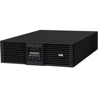
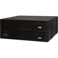
Rear Panel View - 30K and 40K Models
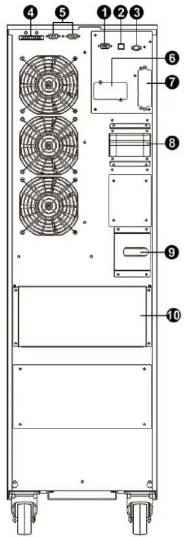
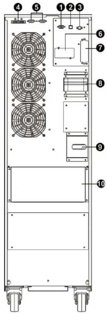
(See next page for number descriptions.)
S3M30KX Rear Panel S3M40KX Rear Panel S3M30KX and S3M40KX Input/Output Terminals
3. Installation and Setup
Front Panel View - 60K and 80K Models
S3M60KX Front View with Door Open
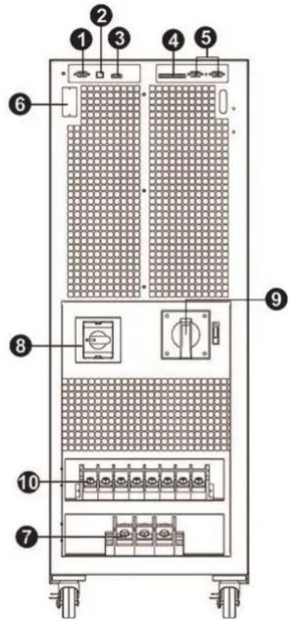
S3M80KX Front View with Door Open
S3M60KX and S3M80KX Input/Output Terminals
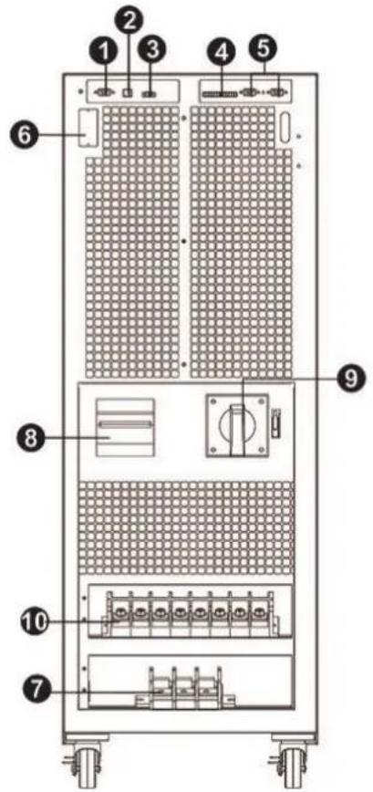
RS-232 Communications Port
2 USB Communications Port
3 Emergency Power Off (EPO) Connector
4 Share Current Port for Paralleling Units
5 Parallel Ports for Paralleling Units
SNMP Slot for Network Monitoring using (Optional WEBCARDLX)
7 External Battery Cabinet Connector
8 Line Input Circuit Breaker/Switch
9 Maintenance Bypass Switch (for Service Personnel Use Only)
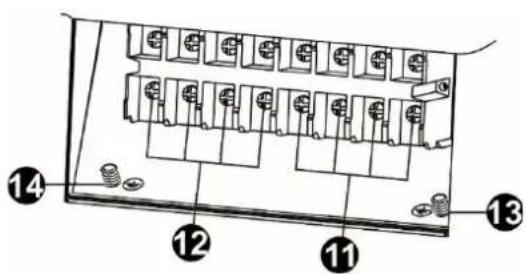
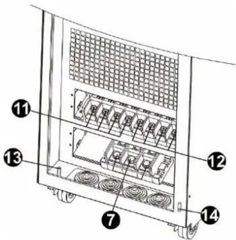
10 Input/Output Terminal (Refer to 11 and 12 for Details)
11 Line Input Terminal
12 Output Terminal (Connects to Mission-critical Loads)
13 Input Grounding Terminal
14 Output Grounding Terminal
3. Installation and Setup
3.2 Internal Battery Connection Procedure for S3M30KX, S3M40KIX, S3M60KX and S3M80KX Models

DANGER! LETHAL HIGH VOLTAGE HAZARD!
Potentially lethal high voltage exists within the batteries, even when not connected to a UPS system. Battery connection should be performed by qualified service personnel only, following all the precautions listed in this manual and adhering to local electrical codes. Refer to section 2.3 BatteryWarnings.
Internal Battery Connection Procedure
1) Remove all screws labeled 1 (Figure 3.1).
2) Remove top plate, right side and left side plates (Figure 3.2).
See next page for steps 3-5.

Figure 3.1 Figure 3.2
3. Installation and Setup
3) For 30kA and 40kVA units with internal batteries, there are four battery cable points that are disconnected for shipping purposes (refer to Figures 3.3 and 3.4). These four cables (two on the right side and two on the left side) will need to be reconnected for proper battery cabinet operation.
Battery cables that need to be reconnected before proper operation of battery cabinet
Figure 3.3 Figure 3.4
4) Re-Install the top and side panels from Step 2.
5) Re-Install and tighten all screws from Step 1 with a torque of 1N· m .
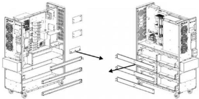
3.3 Installation of Internal Batteries in S3M30KX-NIB and S3M40KX-NIB Models

DANGER! LETHAL HIGH VOLTAGE HAZARD!
Be careful to observe all safety warnings in the manual, especially those in section 2.3 BatteryWarnings.
Battery installation should be performed by qualified electrical service personnel only.
Items needed:
1) Protective equipment (rubber gloves, electrical rated boots, electrical rated rubber floor mat, etc. as outlined in section 2.3 Battery Warnings).
2) 80x Sealed Lead Acid Batteries: 12V 9Ah (Non-Spillable VRLA AGM/GEL). Batteries must be UL-recognized to UL 1989, UL CCN: BARZ2.
3) Tripp Lite Wiring Kit PN: ACC-0442. Check the wiring kit to make sure all necessary items are there. This kit includes:
| CABLE CABLE LENGTH QUANTITY | ||
| 1 | 75 mm 56 | |
| 2 | 160 mm 4 | |
| 3 | 250 mm 9 | |
| 4 | 350 mm 3 | |
| 5 | 700 mm 2 | |
| 6 | 800 mm 1 | |
| 7 | 930 mm 1 | |
3. Installation and Setup
1) Take off top and side panels by removing all screws.
2) Remove the battery bracket bars on the right and left sides of the UPS.
3) Install 11 battery packs to the layer (L1-a). Be sure to keep terminal sides of all batteries up.
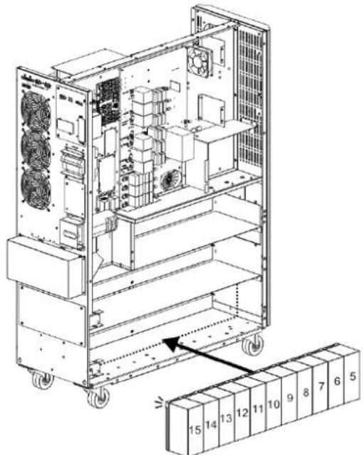
4) Install another 11 battery packs to the layer (L2-a). Be sure to keep terminal sides of all batteries up.
5) Install another 9 battery packs to the layer (L3-a). Be sure to keep terminal sides of all batteries up.
3. Installation and Setup
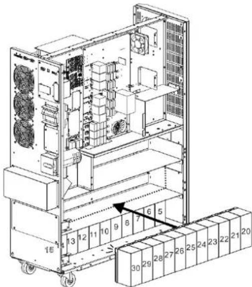
6) Install another 11 battery packs to the layer (L1-b). Be sure to keep terminal sides of all batteries up.

7) Install another 11 battery packs to the layer (L2-b). Be sure to keep terminal sides of all batteries up.
8) Install another 8 battery packs to the layer (L3-b). Be sure to keep terminal sides of all batteries up.
9) Install another 5 battery packs to the layer (L4 and L5). Be sure to keep terminal sides of all batteries up.
3. Installation and Setup
10) Install another 2 battery packs to the layer (L6). Be sure to keep terminal sides of all batteries down.
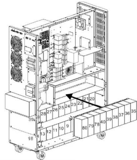
11) Reattach the six battery bracket bars removed in step 2.
12) On the right side of the UPS, use 30 pieces of cable to connect two terminals on all batteries shown below.
3. Installation and Setup
13) Use one cable to connect #51 and #52 batteries.
- Use one cable
6 to connect #75 and #76 batteries.
- Use one cable
5 to connect #67 and #68 batteries.
- Use one cable
4 to connect #64 and #65 batteries.
- Use one cable
2 to connect #62 and #63 batteries.
14) On the left side of the UPS, use 26 pieces of cable to connect two terminals on all batteries.
3. Installation and Setup
15) Use one cable to connect #77 and #78 batteries.
16) Install another 4 battery packs to the layer (L1). Be sure to keep terminal sides of all batteries up.
3. Installation and Setup
17) Use one cable 2 to connect #4 and #5 batteries.
- Use one cable
3 to connect #3 and #4 batteries.
- Use one cable
3 to connect #2 and #3 batteries.
- Use one cable
3 to connect #1 and #2.
18) Install another 4 battery packs to the layer (L2). Be sure to keep terminal sides of all batteries up.
3. Installation and Setup
19) Use one cable to connect #19 and #20 batteries.
- Use one cable
3 to connect #18 and #19 batteries.
- Use one cable
3 to connect #17 and #18 batteries.
- Use one cable
3 to connect #16 and #17 batteries.
- Use one cable
4 to connect #15 and #16 batteries.
20) Install another 4 battery packs to the layer (L3). Be sure to keep terminal sides of all batteries up.
3. Installation and Setup
21) Use one cable to connect #34 and #35 batteries.
- Use one cable
3 to connect #33 and #34 batteries.
- Use one cable
3 to connect #32 and #33 batteries.
- Use one cable
3 to connect #31 and #32 batteries.
- Use one cable
4 to connect #30 and #31 batteries.
22) Reattach the battery brackets.
3. Installation and Setup
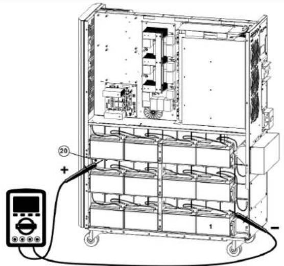
23) Use a meter to measure the positive pole of #20 battery and the negative pole of #1 battery. (DC voltage should be within 240V~270V)
24) Use a meter to measure the positive pole of #40 battery and the negative pole of #21 battery. (DC voltage should be within 240V~270V)

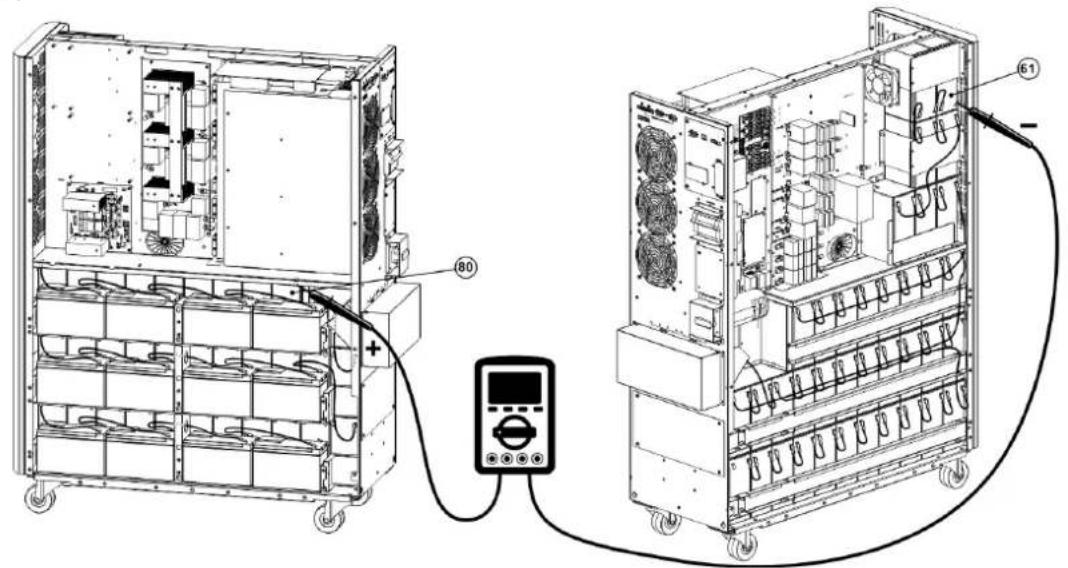
25) Use a meter to measure the positive pole of #80 battery and the negative pole of #61 battery. (DC voltage should be within 240V~270V)
26) Use one meter to measure the positive pole of #60 battery and the negative pole of#41 battery. (DC voltage should be within 240V~270V)

3. Installation and Setup
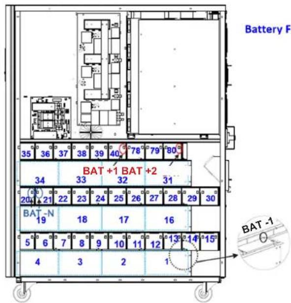
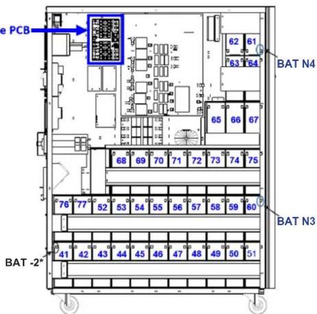
27) Use the Battery Fuse PCB to connect batteries and refer to the Figures 3.5, 3.6 and 3.7. Refer to Table 3.1 for a complete battery wiring listing.
| BAT +1 cable to positive pole of #40 battery. BAT -1 cable to negative pole of #1 battery. |
| BAT +2 cable to positive pole of #80 battery. BAT -2 cable to negative pole of #41 battery.* |
| BAT N1 cable to positive pole of #20 battery. BAT N2 cable to negative pole of #21 battery. |
| BAT N3 cable to positive pole of #60 battery. BAT N4 cable to negative pole of #61 battery. |
Left Side S3M30KX/S3M40KX
Right Side S3M30KX/S3M40KX
* Only the BAT -2 cable and connector is routed through the cable grommet.
Figure 3.5 Figure 3.6
Figure 3.7
Notes:
The blue numbers in above figures are "Battery Numbers" from 1 to 80, which are used for battery position identification.
- There are 2 red wires, 2 black wires and 4 blue wires, which connect the battery fuse board and batteries.
- S3M30KX/NIB battery Fuse board part number: 71-303365-XXG.
- S3M40KX/NIB Battery Fuse board part number: 71-303366-XXG.
3. Installation and Setup
Table 3.1 Battery Wiring for S3M30KX/NIB and S3M40KX/NIB
| BATNumber 1 | 2345678910 | |||||||||||||||||||
| Terminal | - | + | - | + | - | + | - | + | - | + | - | + | - | + | - | + | - | + | - | + |
| Connection Wire | 1050 mm Black Wire | 250 mm Wire | 250 mm Wire | 250 mm Wire | 160 mm Wire | 75 mm Wire | 75 mm Wire | 75 mm Wire | 75 mm Wire | 75 mm Wire | See Below | |||||||||
| BATNumber 10 11 12 13 14 15 16 17 18 19 | ||||||||||||||||||||||
| Terminal | - | + | - | + | - | + | - | + | - | + | - | + | - | + | - | + | - | + | - | + | - | + |
| Connection Wire | 75 mm Wire | 75 mm Wire | 75 mm Wire | 75 mm Wire | 75 mm Wire | 350 mm Wire | 250 mm Wire | 250 mm Wire | 250 mm Wire | See Below | ||||||||||||
| BAT Number | 19 | 20 | 21 | 22 | 23 | 24 | 25 | 26 | 27 | 28 | ||||||||||
| Terminal | - | + | - | + | - | + | - | + | - | + | - | + | - | + | - | + | - | + | - | + |
| Connection Wire | 160 mm Wire | 1350 mm Blue Wire from Fuse Holder | 1350 mm Blue Wire from Fuse Holder | 75 mm Wire | 75 mm Wire | 75 mm Wire | 75 mm Wire | 75 mm Wire | 75 mm Wire | 75 mm Wire | See Below | |||||||||
| BAT Number | 28 | 29 | 30 | 31 | 32 | 33 | 34 | 35 | 36 | 37 | ||||||||||
| Terminal | - | + | - | + | - | + | - | + | - | + | - | + | - | + | - | + | - | + | - | + |
| Connection Wire | 75 mm Wire | 75 mm Wire | 350 mm Wire | 250 mm Wire | 250 mm Wire | 250 mm Wire | 160 mm Wire | 75 mm Wire | 75 mm Wire | See Below | ||||||||||
| BAT Number | 37 | 38 | 39 | 40 | ||||
| Terminal | - | + | - | + | - | + | - | + |
| Connection Wire | 75 mm Wire | 75 mm Wire | 75 mm Wire | 1050 mm Red Wire from Fuse Holder | ||||
| BAT Number | 41 | 42 | 43 | 44 | 45 | 46 | 47 | 48 | 49 | 50 | ||||||||||
| Terminal | - | + | - | + | - | + | - | + | - | + | - | + | - | + | - | + | - | + | - | + |
| Connection Wire | 900 mm BlackWire from Fuse Holder | 75 mm Wire | 75 mm Wire | 75 mm Wire | 75 mm Wire | 75 mm Wire | 75 mm Wire | 75 mm Wire | 75 mm Wire | 75 mm Wire | See Below | |||||||||
| BATNumber 50 51 52 53 54 55 56 57 58 59 | ||||||||||||||||||||||
| Terminal | - | + | - | + | - | + | - | + | - | + | - | + | - | + | - | + | - | + | - | + | - | + |
| Connection Wire | 75 mm Wire | 800 mm Wire | 75 mm Wire | 75 mm Wire | 75 mm Wire | 75 mm Wire | 75 mm Wire | 75 mm Wire | 75 mm Wire | 75 mm Wire | See Below | |||||||||||
| BAT Number | 59 | 60 | 61 | 62 | 63 | 64 | 65 | 66 | 67 | 68 | ||||||||||
| Terminal | - | + | - | + | - | + | - | + | - | + | - | + | - | + | - | + | - | + | - | + |
| Connection Wire | 75 mm Wire | 1350mm Blue Wire from Fuse Holder | 1150mm Blue Wire from Fuse Holder | 75 mm Wire | 160 mm Wire | 75 mm Wire | 350 mm Wire | 75 mm Wire | 75 mm Wire | 700 mm Wire | See Below | |||||||||
| BAT Number | 68 | 69 | 70 | 71 | 72 | 73 | 74 | 75 | 76 | 77 | ||||||||||
| Terminal | - | + | - | + | - | + | - | + | - | + | - | + | - | + | - | + | - | + | - | + |
| Connection Wire | 75 mm Wire | 75 mm Wire | 75 mm Wire | 75 mm Wire | 75 mm Wire | 75 mm Wire | 75 mm Wire | 930 mm Wire | 75 mm Wire | See Below | ||||||||||
| BAT Number | 77 | 78 | 79 | 80 | ||||
| Terminal | - | + | - | + | - | + | - | + |
| Connection Wire | 700 mm Wire | 75 mm Wire | 75 mm Wire | 850 mm Red Wire from Fuse Holder | ||||
28) Reinstall the top and side panels per step 1). Tighten all screws with a torque of 1N· m
3. Installation and Setup
3.4 Single UPS Installation
Installation and wiring must be performed in accordance with local electrical codes/regulations and should only be performed by qualified personnel.
1) Make sure the mains wire and breakers in the building can sustain the rated capacity of the UPS to avoid electric shock or fire hazard.
Note: Using a wall receptacle as the input power source for the UPS may result in the receptacle burning or being destroyed.
2) Switch off the mains switch in the building prior to installation.
3) Turn off all the connected devices before connecting to the UPS.
4) Prepare the power cables according to Table 3.2. Refer to Table 3.3 for UPS Input Breaker sizes and Table 3.4 for Battery Cabinet Batteries and Breaker sizes.

WARNING:
- Before connecting any wires, make sure the AC input and battery power are completely shut off.
Table 3.2 Power Cables
| Model | Wiring Specification | GroundInput | ||||
| S3M30KX 8 AWG [8 mm] | 8 AWG [8 mm] | 4 AWG [21 mm] | N/A, when using only internal batteries 4 AWG [21 mm] | |||
| S3M30KX 8 AWG [8 mm] | 8 AWG [8 mm] | 4 AWG [21 mm] | 4 AWG [21 mm] | 4 AWG [21 mm] | ||
| S3M30KX-NIB 8 AWG [8 mm] | 8 AWG [8 mm] | 4 AWG [21 mm] | 4 AWG [21 mm] | 4 AWG [21 mm] | ||
| S3M40KX 6 AWG [13 mm] | 6 AWG [13 mm] | 4 AWG [21 mm] | N/A, when using only internal batteries 4 AWG [21 mm] | |||
| S3M40KX 6 AWG [13 mm] | 6 AWG [13 mm] | 4 AWG [21 mm] | 4 AWG [21 mm] | 4 AWG [21 mm] | ||
| S3M40KX-NIB 6 AWG [13 mm] | 6 AWG [13 mm] | 4 AWG [21 mm] | 4 AWG [21 mm] | 4 AWG [21 mm] | ||
| S3M60KX 4 AWG [21 mm] | 4 AWG [21 mm] | 1 AWG [42.4 mm] | 1 AWG [42.4 mm] | 4 AWG [21 mm] | ||
| S3M80KX 2 AWG [34 mm] | 2 AWG [34 mm] | 1/0 AWG [54 mm] | 1/0 AWG [54 mm] | 2 AWG [34 mm] | ||
Table 3.3 UPS Input Breakers
| Model (Agency Number) | Breaker Size |
| S3M30KX (AG-030) | 63A, 3-Pole |
| S3M30KX-NIB (AG-031) | 63A, 3-Pole |
| S3M40KX (AG-040) | 80A, 3-Pole |
| S3M40KX-NIB (AG-041) | 80A, 3-Pole |
| S3M60KX (AG-060) | 150A, 3-Pole |
| S3M80KX (AG-080) | 6 x 30A Fuses/Phase |
3. Installation and Setup
Table 3.4 Battery Cabinet Batteries and Breakers
| Model Batteries Included Battery Size and Qty. Breaker Size | |||
| BP480V100 | Pole Yes | 100Ah x 40 400A, 3-Pole | |
| BP480V65 65Ah x 40 300A, 3-Pole | |||
| BP480V40 40Ah x 40 200A, 3-Pole | |||
| BP480V100-NIB | 65Ah x 40 300AN8-Pole | (Designed For) 100Ah x 40 400A, 3-Pole | |
| BP480V65-NIB (Designed For) | |||
| BP480V40-NIB (Designed For) | 40Ah x 40 200A, 3-Pole | ||
| BP480V10 | Yes | 10Ah x 80 100A (Fuse) | |
| BP480V09 9Ah x 80 100A (Fuse) | |||
| BP480V10-NIB No (Designed For) | 10/9Ah x 80 100A (Fuse) | ||
Notes:
- The S3M30KX cable should be able to withstand over 63A current. It is recommended to use 8 AWG (8 mm²) or thicker wire for Phase and 4 AWG (21 mm²) or thicker wire for Neutral for safety and efficiency.
- The S3M40KX cable should be able to withstand over 80A current. It is recommended to use 6 AWG (13 mm²) or thicker wire for Phase and 4 AWG (21 mm²) or thicker wire for Neutral for safety and efficiency.
- The S3M60KX cable should be able to withstand over 122A current. It is recommended to use 4 AWG (21 mm²) or thicker wire for Phase and 1 AWG (42 mm²) or thicker wire for Neutral for safety and efficiency.
- The S3M80KX cable should be able to withstand over 160A current. It is recommended to use 2 AWG (34 mm²) or thicker wire for Phase and 1/O AWG (54 mm²) or thicker wire for Neutral for safety and efficiency.
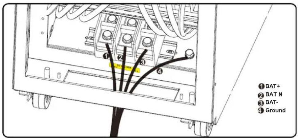
5) Remove the terminal block cover to access the UPS system's input, output and grounding connection terminals. Then connect the wires according to the terminal block diagram shown below. Connect the grounding/earthing wires first when making other wire connections.
Notes:
- Ensure the wires are tightly and securely connected to the terminals.
- Install the output breaker between the output terminal and the load. The breaker should be qualified with leakage current protective function.
- Cabling should be protected by flexible conduit and routed through the appropriate knockouts in the terminal block cover.
Terminal Block Wiring Diagram for S3M30KX and S3M40KX
Terminal Block Wiring Diagram for S3M60K and S3M80K
±240V Battery Connection Wiring
Note: Be sure to also add an equipotential bonding wire between the UPS and the External Battery Cabinets.
6) Re-attach the terminal block cover to the rear panel of the UPS.
3. Installation and Setup

WARNING:
Make sure the UPS is not turned on prior to installation. The UPS should not be turned on until all wiring has been completed and checked.

WARNING:
If an external battery pack is installed, switch off the battery breaker before installation.
Note: Set the battery pack breaker in the "OFF" position, then install the battery pack.
- Pay close attention to the rated battery voltage posted on the rear panel. Connecting battery packs with the incorrect voltage may cause permanent damage to the UPS.
- Pay close attention to the polarity markings on the external battery terminal block and make sure the correct battery polarity is connected. Wrong connection may cause permanent damage to the UPS.
- Ensure the protective earth ground wiring is correct. The wire current spec, colour, position, connection and conductance reliability should be carefully observed.
- Ensure the utility input and output wiring is correct. The wire current spec, colour, position, connection and conductance reliability should be checked carefully. Make sure the R, S, T and N wiring is correct, not reversed and not short-circuited.
3.5 UPS Installation for Parallel Systems

WARNING:
Installation and wiring must be performed in accordance with the local codes/regulations and installed using the following instructions by a qualified electrical service technician only.
If the UPS is only used for single operation, you may skip this section and proceed to section 3.7.
1) Parallel configuration supports up to three UPS systems. Do not attempt to link more than three UPS systems via parallel configuration.
2) Install and wire the UPS system according to section 3.5 guidelines.
3) When installing the parallel system, the length of input wires (R, S, T, N) in one UPS must be equal to the input wires of the other UPS. Likewise, the length of output wires (R, S, T, N) must also be in equal length. If not, it will cause unbalance current on the output load.
4) Connect the input wiring of each UPS to an input breaker.
5) Connect all input breaker wiring to a main input breaker.
6) Connect the output wiring of each UPS to an output breaker.
7) Connect all output breakers to a main output breaker. This main output breaker will directly connect to the loads.
8) If an external battery pack is used, each UPS must be connected to an independent battery pack or a common battery pack. Note: The parallel system cannot use a common external battery pack. Doing so will cause permanent damage to the entire system.
9) Refer to the following wiring diagram for parallel installation:
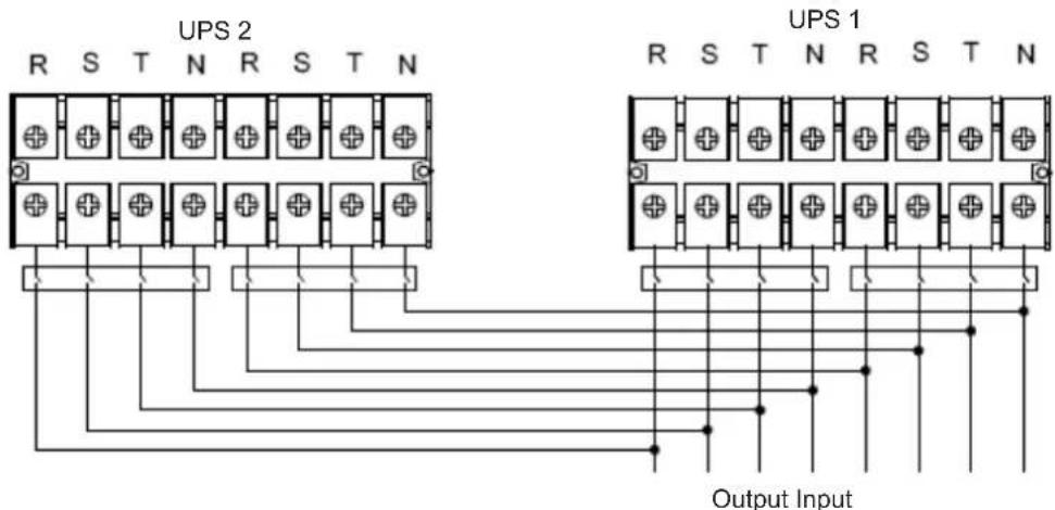
Wiring Diagram of Parallel System S3M30KX, S3M40KX, S3M30KX/NIB and S3M40KX/NIB Models
3. Installation and Setup
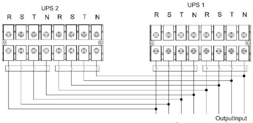
Wiring Diagram of Parallel System (S3M60KX and S3M80KX Models)
3.6 External Battery Connection
The S3M30KX/NIB and S3M40KX/NIB UPS models include a robust internal battery system. The S3M60KX and S3M80KX models require external battery packs. External battery packs may be used with the S3M30KX and S3M40KX models to extend runtime. Adding external batteries will increase runtime and require additional recharge time.*
The illustrations below show the location of the UPS system's external battery connector for the 30K and 40K model where the battery pack connects. The illustration at the bottom shows the connection for the 60K and 80K models. Follow the installation instructions for your battery pack as they appear in your battery pack Owner's Manual. Ensure the cables are fully inserted into their connectors. Small sparks may occur during battery connection; this is normal.
Do not connect or disconnect battery packs when the UPS is running on battery power.
*Limit three external battery packs per UPS.
External Battery Connector for the S3M30KX/NIB and S3M40KX/NIB Models
S3M30KX/NIB and S3M40KX/NIB External Battery Connection
S3M60KX and S3M80KX External Battery Connection
4. Operation
4.1 Display Button Operation
| Button Function | |
| ON/Enter Button | Turn on the UPS: Press and hold for more than 0.5 seconds to turn on the UPS. Enter Button: Press to confirm a selection in the settings menu. |
| OFF/ESC Button | Turn off the UPS: Press and hold for more than 0.5 seconds to turn off the UPS. Esc Button: Press to return to the previous menu in the settings menu. |
| Test/Up Button | Battery Test: Press and hold for more than 0.5 seconds to test the battery while in On-line mode and Freq. Converter* mode. UP Button: Press to display the next selection in the settings menu. |
| Mute/Down Button | Mute the alarm: Press and hold for more than 0.5 seconds to mute the alarm. Refer to section 4.4.9 for details. Down Button: Press to display the previous selection in the settings menu. |
| Test/Up + Mute/Down Button | Press and hold the two buttons simultaneously for more than 1 second to enter/exit the setup menu. Refer to section 4.7 Setup Menu for details. |
- Freq. Converter means Constant Output Voltage and Constant Output Frequency.
4.2 LED Indicators and LCD Panel
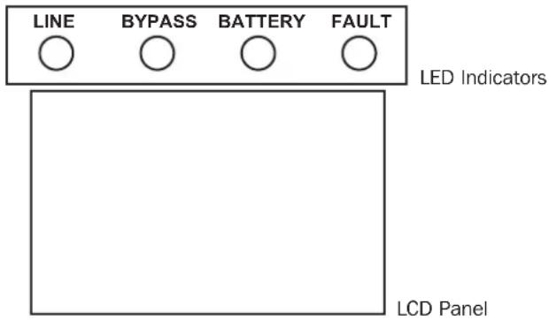
LED Indicators:
There are four LEDs on front panel to show the UPS operation status:
| Mode / LED Line Bypass | Battery Fault | |||
| Initialization ···· | ||||
| Standby mode o o o o | ||||
| Bypass mode o · o o | ||||
| On-line mode · o o o | ||||
| Battery mode o o · o | ||||
| Freq. Converter* mode · o o | ||||
| Battery test ····o | ||||
| ECO mode | ···o o | |||
| Fault | o o o · |
Note: means LED is glowing, and o means LED is off.
4. Operation
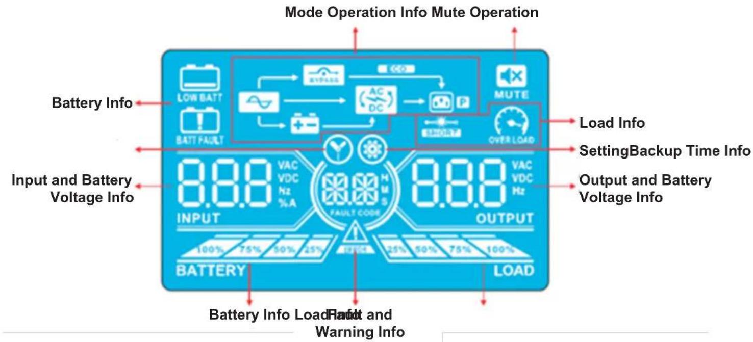
LCD Panel
| Display Function | |
| Backup time information | |
| Indicates the battery discharge time in numbers H: hours, M: minutes, S: seconds | |
| Fault and Warning information | |
| Indicates a Warning when this icon is flashing and a Fault when this icon is steady. | |
| When the Fault and Warning Icon is steady, refer to the Fault code description in section 4.9. When the icon is flashing, refer to the Warning code description in section 4.11. | |
| Mute operation | |
| Indicates the UPS alarm is disabled. | |
| Output & Battery voltage information | |
| Indicates the output voltage, frequency or battery voltage. VAC: Output Voltage, VDC: Battery Voltage, Hz: Frequency | |
| Load information | |
| Indicates the load level by 0-25%, 26-50%, 51-75%, and 76-100%. | |
| Indicates overload. | |
| Indicates the load or the output is short. | |
| Mode operation information | |
| Indicates the UPS is connected to the mains. | |
| Indicates the battery is working. | |
| Indicates the bypass circuit is working. | |
| Indicates ECO Mode is enabled. | |
| Indicates the inverter circuit is working. | |
| Indicates the output is working. | |
4. Operation
| Battery information | |
| 100% 75% 36% 20% BATTERY | Indicates the battery capacity by 0-25%, 26-50%, 51-75% and 76-100%. |
| BATTERY | Indicates the battery is not connected. |
| LOR BART | Indicates low battery level and low battery voltage. |
| Input & Battery voltage information | |
| 888 VDC INPUT | Indicates the input voltage, frequency or battery voltage. VAC: Input Voltage, VDC: Battery Voltage, Hz: Input Frequency |
4.3 Audible Alarm
| Description Alarm Status Mutable | ||
| UPS Status | ||
| Bypass Mode Beeps once every 2 minutes | YesBattery Mode Beeps once every 4 seconds. | |
| Fault Mode Beeps continuously. | ||
| Warning | ||
| Overload Beeps twice per second. | No | |
| All other warnings Beeps once per second. | ||
| Fault | ||
| All Beeps continuously. Yes | ||
4.4 Single UPS Operation
4.4.1 Turning On the UPS (On-line Mode)
1) Make sure the power supply is correctly connected. If you have an external battery pack, set the breaker of the battery pack to the "ON" position, then switch the UPS input breaker to the "ON" position. At this time, the fan will be running and the UPS will proceed to power-on for initialization. Several seconds later, the UPS will operate in Bypass Mode and supply power to the connected loads via the bypass.
Note: In Bypass Mode, the load is not protected by the UPS. To protect connected devices, turn on the UPS as shown in Step 2.
2) Press and hold the "ON" button for 0.5 seconds to turn on the UPS. The alarm will beep once.
3) A few seconds later, the UPS will enter On-line Mode. If utility power is abnormal, the UPS will operate in Battery Mode without interruption.
Note: When the UPS is running low on battery power, it will automatically shut down in Battery Mode. The UPS will auto restart in On-line Mode once utility power is restored.
4.4.2 Turning on the UPS without Utility Power (Battery Mode)
1) When using an external battery pack, make sure the two battery strings are correctly connected before switching the battery pack breaker to the "ON" position.
2) Switch the battery pack breaker to the "ON" position.
3) Press the "ON" button to set up the power supply for the UPS. The UPS will enter Power-on Mode. After initialization, the UPS will enter "No Output Mode"/Standby Mode. When this happens, press and hold the "ON" button for 0.5 seconds to turn on the UPS. The alarm will beep once.
4) A few seconds later, the UPS will turn on and enter Battery Mode.
4. Operation
4.4.3 Connecting Devices to UPS
1) After the UPS has been turned on, devices may be connected and powered on one at a time. The UPS system's LCD panel will display the total load level.
2) When connecting devices with inductive loads (such as a printer), the in-rush current should be calculated carefully to confirm it meets the capacity of the UPS. Power consumption of such loads may cause an overload.
3) If the UPS is overloaded, the alarm will beep twice every second.
4) In case of overload, remove non-essential devices immediately. To prevent overload and ensure system safety, it is recommended to have the total load connected to the UPS at no more than 80% of its nominal power capacity.
5) If the overload time is higher than the acceptable time listed in On-line Mode, the UPS will automatically transfer to Bypass Mode. After the overload is removed, the UPS will return to On-line Mode. If the overload time is higher than the acceptable time listed in Battery Mode, the UPS will go to fault status. At this time, if the bypass is enabled, the UPS will supply power to the load via bypass. If the bypass function is disabled or the input power is not within acceptable bypass range, it will directly cut off output.
4.4.4 Charging the Batteries
1) After the UPS is connected to utility power, the charger will automatically charge the batteries (except when in Battery Mode, during a battery self-test, overload or when the batteries are fully charged).
2) It is recommended to charge the batteries at least 10 hours prior to use. Otherwise, the backup time may be shorter than expected.
4.4.5 Battery Mode Operation
1) The default value is 990 minutes, or 16.5 hours. The UPS will automatically shut down to protect the battery after discharging for 16.5 hours. This battery discharge protection can be enabled or disabled through the LCD control panel (refer to section 4.7 for more information).
4.4.6 Testing the Batteries
1) To check the battery status when the UPS is in On-line Mode/Freq. Converter Mode, press the "Test" button for the UPS to perform a battery self-test.
2) Users may set battery self-tests through the network management card.
4.4.7 Turning Off the UPS with Utility Power Present in On-line Mode
1) Turn off the UPS inverter by pressing the "OFF" button for at least 0.5 seconds. The alarm will beep once and the UPS will enter Bypass Mode.
Notes:
If the UPS has been set to bypass output, it will bypass voltage from utility power to the output terminal, even though the UPS inverter has been turned off.
After turning off the UPS, be aware that the UPS is operating in Bypass Mode and there is risk of power loss for connected devices.
2) In Bypass Mode, UPS output voltage is still present. In order to cut off the output, switch off the line input breaker. Within a few seconds, the unit's LCD panel will be blank and the UPS will be completely off.
4.4.8 Turning off the UPS with No Utility Power Present in Battery Mode
1) Turn off the UPS by pressing the "OFF" button for at least 0.5 seconds. The alarm will sound once.
2) The UPS will cut off power to output and the LCD panel will be blank.
4.4.9 Muting the Alarm
1) To mute the alarm, press the "Mute" button for at least 0.5 seconds. If the Mute button is pressed after the alarm is muted, the alarm will reactivate.
2) Some warning alarms cannot be muted unless the error is fixed. Refer to section 4.3 for details.
4.4.10 Operation in Warning Status
1) When the Fault LED flashes and the alarm sounds once every second, the UPS is encountering problems with its operation. Users may view the warning indicator from the LCD panel. Check the troubleshooting table in section 6 for more information.
2) Some warning alarms cannot be muted until the error is fixed. Refer to section 4.3 for details.
4. Operation
4.4.11 Operation in Fault Mode
1) When the Fault LED illuminates and the alarm sounds continuously, there is a fatal error in the UPS. Users can view the fault code from the LCD panel. Refer to the table in section 6. Troubleshooting for more information.
2) Check the loads, wiring, ventilation, utility, battery, etc. after a fault occurs. Do not attempt to turn on the UPS again until the problem is resolved. If the problem cannot be fixed, please contact Tripp Lite Tech Support.
3) In the event of an emergency, immediately cut off the utility connection, external battery, and output to avoid further risk or danger.
4.4.12 Operation in Maintenance Mode (for Models with a Maintenance Bypass Switch Only)
1) This operation should only be performed by maintenance personnel or qualified technicians. When the UPS needs to be repaired or serviced and the load cannot be shut off, the UPS should be put into Maintenance Mode.
2) First, switch off the UPS.
3) Remove the cover of the maintenance bypass switch.
4) Turn the maintenance switch to "BPS" position.

Warning: (for Parallel System Setups Only)
- Before turning on the parallel system to activate the inverter, make sure all UPS maintenance switches are set to the same position.
- When the parallel system is turned on to work through the inverter, do not operate the maintenance switch of any unit.
4.5 Parallel UPS Operation
4.5.1 Parallel System Initial Startup
Before initial startup, ensure all UPS systems have the same configuration and can be connected in parallel.
1) Turn on each UPS to On-line Mode (refer to section 4.4.1). Using a multimeter, measure the inverter output voltage of each phase for each UPS to confirm that the inverter voltage difference between actual output and setting value is less than 1.5V (typically 1V). If the difference is greater than 1.5V , calibrate the voltage by configuring the inverter voltage adjustment (refer to Program Codes 15, 16 and 17, in section 4.7) in the LCD setting. If the voltage difference after calibration remains greater than 1.5V , contact Tripp Lite Technical Support for further assistance.
2) Calibrate the output voltage measurement by configuring the output voltage calibration (refer to Program Codes 18, 19, and 20, in section 4.7) in the LCD panel to ensure the difference between the real output voltage and the detected value of the UPS is less than 1V.
3) Turn off each UPS (refer to section 4.4.7), then follow the wiring procedure in section 3.4.
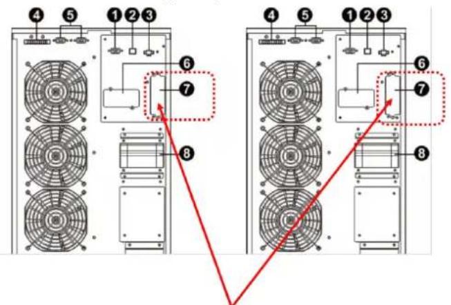
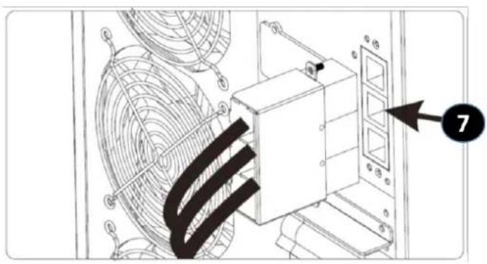
4) Remove the metal cover to access the parallel communication ports on the UPS. Connect each UPS one at a time (maximum of three units for parallel installation) with the parallel cable and shared current cable. Follow the parallel communication cable configuration in the figure below, then reinstall the metal cover.
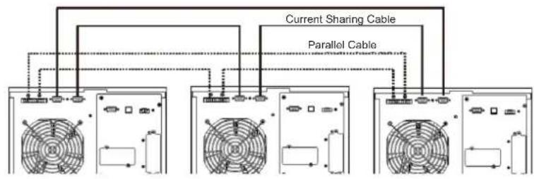
S3M30KX, S3M40KX S3M30KX/NIB and S3M40KX/NIB Parallel System UPS Wiring
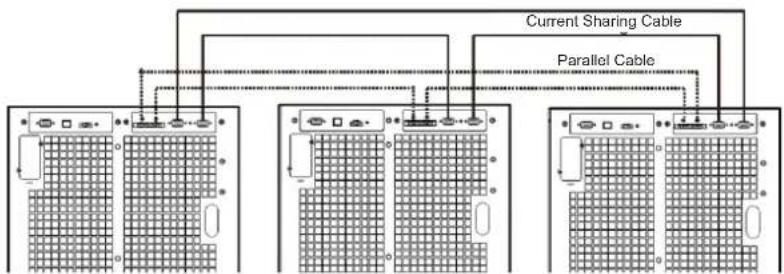
S3M60KX and S3M80KX Parallel System UPS Wiring
4. Operation
4.5.2 Turning On a Parallel System in On-line Mode
1) Turn on the line input breaker of each UPS, then turn on the external main input breaker. When all UPS systems enter Bypass Mode, measure the output voltage between two UPS systems for the same phase to ensure the phase sequence is correct. If these two voltage differences are near zero, then all connections are correct. If not, check to see if the wirings are connected correctly.
2) Turn on the output breaker of each UPS.
3) Turn on each UPS one at a time. The UPS systems will then enter On-line Mode synchronously. The parallel system is completed.
4.5.3 Turning On the Parallel System in Battery Mode
1) Turn ON the battery breaker and output breaker of each UPS.
Note: UPS may share the same battery bank or use separate battery banks while in a parallel system.
2) Turn on any UPS. A few seconds later, the UPS will enter Battery Mode.
3) Turn on another UPS. A few seconds later, the UPS will enter Battery Mode and add to the parallel system.
4) If there is a third UPS in the setup, follow the same procedure as outlined above. The parallel system is complete.
4.5.4 Adding a New Unit to the Parallel System
1) A new unit cannot be added to the parallel system when the whole system is in operation. The load must be powered off and the UPS system shut down.
2) Make sure all UPS systems can be connected in parallel. Follow the wiring instructions in section 3.4.
4.5.5 Removing a Unit from the Parallel System
There are two methods to remove a unit from the parallel system:
Method 1:
1) Press the "OFF" key twice, each time for more than 0.5 seconds. The UPS will enter into Bypass Mode or Standby Mode without output.
2) Turn off the unit's output breaker and input breaker.
3) After the unit shuts down, turn off the battery breaker and remove the parallel cable and shared current cables. Remove the unit from the parallel system.
Method 2:
1) If the UPS indicates a bypass abnormal error code, you cannot remove the UPS without interruption and must first power down the load and the UPS system.
2) Make sure the bypass setting is enabled in each UPS, then turn off the running system. All UPS systems will transfer to Bypass Mode. Remove all the maintenance bypass covers and set the maintenance switches from "UPS" to "BPS". Turn off all input breakers and battery breakers in the parallel system.
3) Turn off the output breaker and remove the parallel cable and shared current cable of the UPS to be removed. Remove the unit from the parallel system.
4) Turn on the input breaker of the remaining UPS system(s), then turn on the external main input breaker. The system(s) will transfer to Bypass Mode. Set the maintenance switches from "BPS" to "UPS" and reattach the maintenance bypass covers.
5) Turn on the remaining UPS systems.

Warning: (for Parallel System Setups Only)
- Before turning on the parallel system to activate the inverter, make sure all UPS maintenance switches are set to the same position.
- When the parallel system is turned on to work through the inverter, do not operate the maintenance switch of any unit.
- The parallel system DOES NOT support ECO Mode. DO NOT enable ECO Mode in any unit.
4. Operation
4.6 LCD Panel Abbreviations
| Abbreviation | Display content Meaning | |
| ENA | ENA | Enable |
| DIS | DIS | Disable |
| ATO | REC | Auto |
| BAT | BAT | Battery |
| NCF | NCF | Normal Mode (not CVCF Mode) |
| CF | CF | CVCF Mode |
| SUB | SUB | Subtract |
| ADD | Add | Add |
| ON | ON | On |
| OFF | OFF | Off |
| FBD | Fbd | Not allowed |
| OPN | OPN | Allow |
| Abbreviation | Display content | Meaning |
| RES | RES | Reserved |
| N.L | NL | Neutral line loss |
| CHE | CHE | Check |
| OP.V | OPL | Output voltage |
| PAR | PAR | Parallel, 001 means the first UPS |
| RN | RN | The first phase |
| SN | SN | The second phase |
| TN | TN | The third phase |
| RS | RS | The first line |
| ST | ST | The second line |
| TR | TR | The third line |
| HS.H | HSH | Hot standby |
4.7 Setup Menu
Press and hold the Test/Up and Mute/Down buttons simultaneously for longer than one second to enter/exit the Setup Menu.
There are three parameters to set up the UPS. Refer to the illustration below.
Parameter 1 is for program alternatives. Refer to below tables for the programs to set up.
Parameter 2 and Parameter 3 are the setting options or values for each program.
The display will time out after 10 minutes of inactivity. This feature is always enabled.
Note: Use the "Up" or "Down" button to change the programs or parameters.
Parameter 1
Parameter 2 Parameter 3
4. Operation
Programs Available List for Parameter 1:
| Code Description | Bypass / No Output mode | AC Mode | ECO Mode | CVCF Mode | Battery Mode | Battery Test |
| 01 Output voltage Y* | ||||||
| 02 Output frequency Y | ||||||
| 03 Voltage range for bypass Y | ||||||
| 04 Frequency range for bypass Y | ||||||
| 05 ECO Mode enable/disable Y | ||||||
| 06 Voltage range for ECO Mode Y | ||||||
| 07 Frequency range for ECO Mode Y | ||||||
| 08 Bypass Mode setting Y Y | ||||||
| 09 Maximum battery discharge time setting Y Y Y Y Y Y | ||||||
| 10 Reserved Reserved for future options | ||||||
| 11 Hot standby function setting | Y | |||||
| 12 Neutral loss detection | YYYYYY | |||||
| 13 Battery voltage calibration | YYYYYY | |||||
| 14 Charger voltage adjustment YYYYYYY | ||||||
| 15 Inverter A voltage adjustment | Y | YY | ||||
| 16 Inverter B voltage adjustment | Y | YY | ||||
| 17 Inverter C voltage adjustment | Y | YY | ||||
| 18 Output A voltage calibration | Y | YY | ||||
| 19 Output B voltage calibration | Y | YY | ||||
| 20 Output C voltage calibration | Y | YY | ||||
| 21 Charger current setting | Y | |||||
| 22 Charging boards quantity setting | Y | |||||
*Y means that this program can be set in this mode.
Note: All parameter settings will be saved only when the UPS shuts down normally with an internal or external battery connection. Normal UPS shutdown means turning off input breaker in Bypass/No Output Mode.
01: Output Voltage
| Interface | Setting |
| BATTERY OUTPUT | Parameter 3: Output voltage For 220/230/240V AC models, you may choose the following output voltage: 220: Output voltage is 220V AC. 230: Output voltage is 230V AC (Default). 240: Output voltage is 240V AC. |
4. Operation
02:Output Frequency
| Interface Setting | |
| 60 Hz, CVCF Mode | |
| 50 Hz, Normal Mode | |
| ATO |
03: Voltage Range for Bypass
| Interface Setting | |
| 176 (03) 264 BATTERY LOAD | Parameter 2: Set the acceptable low voltage for bypass. For 220/230/240V AC models, setting range is from 176V to 209V and the default value is 176V. Parameter 3: Set the acceptable high voltage for bypass. For 220/230/240V AC models, setting range is from 231V to 276V and the default value is 264V. |
04: Frequency Range for Bypass
| Interface Setting | |
| 468 538Battery LOAD | Parameter 2: Set the acceptable low frequency for bypass. 50 Hz system: Setting range is from 46.0 Hz to 49.0 Hz. 60 Hz system: Setting range is from 56.0 Hz to 59.0 Hz. The default value is 46.0 Hz/56.0 Hz. Parameter 3: Set the acceptable high frequency for bypass. 50 Hz: Setting range is from 51.0 Hz to 54.0 Hz. 60 Hz: Setting range is from 61.0 Hz to 64.0 Hz. The default value is 54.0 Hz/64.0 Hz. |
05:ECO Mode Enable/Disable
| Interface Setting | |
| BATTERY LOAD | Parameter 3: Enable or disable the ECO function. You may choose the following two options: DIS: Disable ECO function (Default). ENA: Enable ECO function. If the ECO function is disabled, the voltage range and frequency range for ECO Mode still can be set, but is void unless the ECO function is enabled. *If the system is running in parallel, be sure to set “DIS” only. |
4. Operation
06: Voltage Range for ECO Mode
| Interface Setting | |
| 209 06 23 15 BATTERY LOAD | Parameter 2: Low voltage point in ECO Mode. The setting range is from -5% to -10% of the nominal voltage. Parameter 3: High voltage point in ECO Mode. The setting range is from +5% to +10% of the nominal voltage. |
07: Frequency Range for ECO Mode
| Interface Setting | |
| 480 520 BATTERY LOAD | Parameter 2: Set the low frequency point for ECO Mode. 50 Hz system: Setting range is from 46.0 Hz to 48.0 Hz. 60 Hz system: Setting range is from 56.0 Hz to 58.0 Hz. The default value is 48.0 Hz/58.0 Hz. Parameter 3: Set high frequency point for ECO Mode. 50 Hz: Setting range is from 52.0 Hz to 54.0 Hz. 60 Hz: Setting range is from 62.0 Hz to 64.0 Hz. The default value is 52.0 Hz/62.0 Hz. |
08: Bypass Mode Setting
| Interface Setting | |
| BATTERY LOAD | Parameter 2: OPN: Bypass allowed. When selected, the UPS will run in Bypass Mode depending on whether the bypass setting is enabled/disabled. FBD: Bypass not allowed. When selected, Bypass Mode is not allowed in any situation. Parameter 3: ENA: Bypass enabled. When selected, Bypass Mode is activated (Default). DIS: Bypass disabled. When selected, automatic bypass is acceptable, but manual bypass is not allowed. Manual bypass means users manually operate UPS for Bypass Mode. For example, pressing OFF button in AC Mode to turn into Bypass Mode. |
09: Maximum Battery Discharge Time Setting
| Interface Setting | |
| 990 BATTERY LOAD | Parameter 3: 000~999: Set the maximum discharge time from 0 to 999 min. The UPS will shut down to the protect battery if the discharge time arrives before the battery is under voltage. The default value is 990 min. DIS: Disable battery discharge protection and backup time will depend on battery capacity. |
10: Reserved
| Interface Setting | |
| SEETO DISBATTERYLOAD | Reserve for future options. |
4. Operation
11: Hot Standby Function Setting
| Interface Setting | |
| HSH YES BATTERY LOAD | Parameter 2:HS.H: Indicates hot standby function. Parameter 3: Enable or disable hot standby function.YES: Hot standby function is enabled. The current UPS is set to host the hot standby function and will restart after AC recovery, even without the battery connected.NO: Hot standby function is disabled. The UPS is running in Normal Mode and cannot restart without battery. |
12: Neutral Loss Detection
| Interface Setting | |
| BATTERY | Parameter 2: N.L: Indicates neutral loss detection function. Parameter 3: DIS: Disable the neutral loss detection function. The UPS will not detect a neutral loss. ATO: The UPS will automatically detect whether or not the neutral is lost. If neutral loss is detected, an alarm will be generated. If the UPS is turned on, it will transfer to Battery Mode. When neutral is restored and detected, the alarm will automatically be muted and the UPS will automatically return to Normal Mode. CHE: The UPS will automatically detect the neutral loss. If neutral loss is detected, an alarm will be generated. If the UPS is turned on, it will transfer to Battery Mode. When neutral is restored, the alarm will NOT be muted automatically and the UPS will NOT return to Normal Mode automatically. Here, you must mute the alarm and make the UPS manually return to Normal Mode. The operation is: First, enter this menu and press the “Enter” key to make the “CHE” flash. Second, press the “Enter” key again to activate the neutral detection (check). If neutral is detected, the alarm will be muted and the UPS will return to Normal Mode. If neutral is not detected, the alarm will continue to go off until the neutral is detected at the next manual checking operation. CHE is the default setting. |
13: Battery Voltage Calibration
| Interface Setting | |
| BATTERY LOAD | Parameter 2: Select "Add" or "Sub" function to adjust battery voltage. Parameter 3: The voltage range is 0V to 9.9V. The default value is 0V. |
14: Charger Voltage Adjustment
| Interface Setting | |
| BATTERY LOAD | Parameter 2: Choose Add or Sub to adjust charger voltage. Parameter 3: The voltage range is 0V to 9.9V. The default value is 0V. Notes: *Before making voltage adjustments, be sure to disconnect all batteries first to get the accurate charger voltage. * Any modification should be suitable to battery specifications. |
4. Operation
15: Inverter-A Voltage Adjustment
| Interface Setting | |
| BATTERY LOAD | Parameter 2: Choose Add or Sub to adjust inverter-A voltage.*Parameter 3: The voltage range is 0V to 9.9V. The default value is 0V.* Add or Sub is according to the output voltage that you set. |
16: Inverter-B Voltage Adjustment
| Interface Setting | |
| BATTERY LOAD | Parameter 2: Choose Add or Sub to adjust inverter-B voltage*. Parameter 3: The voltage range is 0V to 9.9V. The default value is 0V. *It will display number 1 under 0 to represent inverter-B voltage. |
17: Inverter-C Voltage Adjustment
| Interface Setting | |
| BATTERY LOAD | Parameter 2: Choose Add or Sub to adjust inverter-C voltage*. Parameter 3: The voltage range is 0V to 9.9V. The default value is 0V. *It will display number 2 under P456B to represent inverter-C voltage. |
18: Output-A Voltage Calibration
| Interface Setting | |
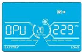
| BATTERY | Parameter 2: Always shows OP.V as output voltage. Parameter 3: Shows the internal measurement value of the output-A voltage. You can calibrate it by pressing Up or Down according to the measurement from an external voltage meter. The calibration result will be effective by pressing Enter. The calibration range is limited within +/-9V. This function is normally used for parallel operation. |
19: Output-B Voltage Calibration
| Interface Setting | |
| BATTERY LOAD | Parameter 2: Always shows OP.V as output voltage*. Parameter 3: Shows the internal measurement value of the output-B voltage. You can calibrate it by pressing Up or Down according to the measurement from an external voltage meter. The calibration result will be effective by pressing Enter. The calibration range is limited within +/-9V. This function is normally used for parallel operation. *It will display number 1 under OP.U to represent the output B voltage. |
4. Operation
20: Output-C Voltage Calibration
Interface Setting
Parameter 2: Always shows OP.V as output voltage.
Parameter 3: Shows the internal measurement value of the output-C voltage. You can calibrate it by pressing Up or Down according to the measurement from an external voltage meter. The calibration result will be effective by pressing Enter. The calibration range is limited within +/-9V . This function is normally used for parallel operation.
*It will display number 2 under QPU to represent the output C voltage.
21: Current Charger Setting
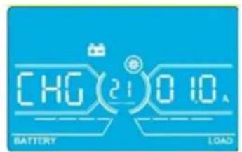
Interface Setting
Parameter 2: CHG indicates adjust charger current function.
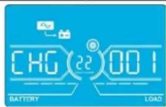
Parameter 3: Set the charger current. The setting range is 1A to 4A. The default value is 2A for 30K/40K and 4A for 60K/80K.
- 30K-40K: Adjust the charger current function only for one charger board installed on UPS. This feature will not work when more than one charger board is installed.
- 60K-80K: Adjust charger current function for only two charger boards installed on UPS. This feature will not work when more than two charger boards are installed.
Note: Once the charger board is extended, all installed charger boards will charge the battery at the maximum power of 4A current. Extension board kits are available for the S3M30KX and S3M40KX models (CBKIT30-40) and the S3M60KX and S3M80KX models (CBKIT30-80).
22:Charging Boards Number Setting
Interface Setting
Parameter 2: CHG indicates adjust charging boards quantity function.
Parameter 3: Set the charging boards quantity. The setting range is from 1 to 3 and the default value is 1.
- 60K-80K: Two charger boards are one group. If the UPS installs four charger boards, it needs to be set to 2. If the UPS installs six charger boards, it needs set to 3.
Note: Once the charger board is extended, this parameter has to be changed accordingly.
4.8 Operating Mode/Status Description
The following table shows the LCD screen for operating modes and status.
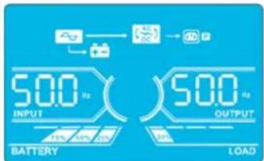
(1) If the UPS is in normal operation, it will show seven screens one-by-one, which represents 3-phase input voltages (An, bn, Cn), 3-line input voltages (Ab, bC, CA) and frequency in turns.
(2) If parallel UPS systems are successfully set up, it will show one more screen with "PAR" in Parameter 2 and assigned number in Parameter 3 (as shown in the below parallel screen illustration). The primary UPS will be assigned automatically as "001". Secondary UPS systems will be assigned as either "002" or "003". The assigned numbers may be changed dynamically in the operation.
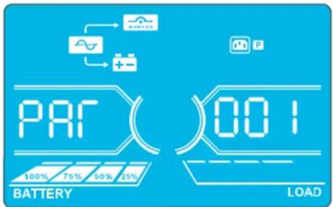
Parallel Screen
4. Operation
| Operating Mode/Status | |||
| UPS Power On | Description | When the UPS is powered on, it will enter into this mode for a few seconds as the CPU and system initialise. | |
| LCD Panel | |||
| No-output Mode | Description When bypass voltage/frequency is out of acceptable range or bypass is disabled (or forbidden), the UPS will enter No-output Mode if powering on or turning off the UPS. This means the UPS has no output. The alarm will beep every two minutes. | ||
| LCD Panel | |||
| AC Mode Description When input voltage is within acceptable range, the UPS will provide pure and stable AC power to output. The UPS will also charge the battery at AC mode. | |||
| LCD Panel | |||
4. Operation
AC Mode (continued)
ECO Mode Description When the input voltage is within voltage regulation range and ECO Mode is enabled, UPS will bypass voltage to output for energy saving.
LCD Panel

4. Operation
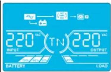
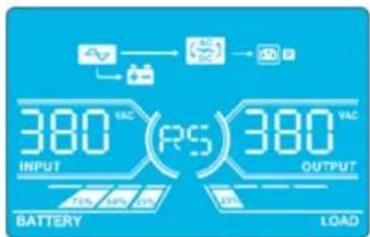
| CVCF Mode Description When the output frequency is set to “CF”, the inverter will output constant frequency (50 Hz or 60 Hz). In this mode, the UPS will have no bypass output but still charge the battery. | |||
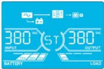
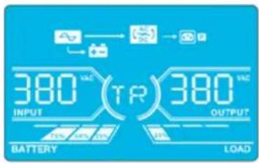
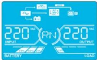
| LCD Panel | 220VAC(RN)220VAC BATTERY LOAD | 220VAC(SN)220VAC BATTERY LOAD | |
| 220VAC(TN)220VAC BATTERY LOAD | 380VAC(RS)380VAC BATTERY LOAD | ||
| 380VAC(ST)380VAC BATTERY LOAD | 380VAC(TR)380VAC BATTERY LOAD | ||
| 600VAC(CF)500VAC BATTERY LOAD | |||
| Battery Mode | Description | When the input voltage/frequency is beyond the acceptable range or experiences a power failure, the UPS will provide backup power from the battery. The alarm will beep every 4 seconds. | |
| LCD Panel | 260VAC(RN)220VAC BATTERY LOAD | 260VAC(SN)220VAC BATTERY LOAD | |
| 260VAC(TN)220VAC BATTERY LOAD | 260VAC(RS)380VAC BATTERY LOAD | ||
| 260VAC(ST)380VAC BATTERY LOAD | 260VAC(TR)380VAC BATTERY LOAD | ||
4. Operation
| Battery Mode(continued) | 260 VDC30 S00 OutputBATTERY LOAD | ||
| Bypass Mode | Description | When input voltage is within acceptable range and bypass is enabled, turn off the UPS and it will enter Bypass Mode. The alarm will beep every two minutes. | |
| LCD Panel | 220 AC(RN)220 ACINPUT OUTPUTBATTERY LOAD | ||
| 220 AC(TN)220 ACINPUT OUTPUTBATTERY LOAD | |||
| 380 AC(ST)380 ACINPUT OUTPUTBATTERY LOAD | |||
| 380 AC(TR)380 ACINPUT OUTPUTBATTERY LOAD | |||
| 500 AC(SN)500 ACOUTPUTBATTERY LOAD | |||
| Battery Test | Description | When the UPS is in AC Mode or CVCF Mode, press the "Test" button for more than 0.5 seconds. The UPS will beep once. The line between I/P and inverter icons will blink to remind users this operation is used to check the battery status. | |
| LCD Panel | 229 DC(RN)220 ACINPUT OUTPUTBATTERY LOAD | ||
| 229 DC(SN)220 ACINPUT OUTPUTBATTERY LOAD | |||
4. Operation
| Battery Test(continued) | 229 VCC(ST)380 VCCINPUT OUTPUTBATTERY LOAD | 229 VCC(TR)380 VCCOUTPUTBATTERY LOAD | |
| 229 VCC(06)500V OUTPUTBATTERY LOAD | |||
| Warning Status | Description | If some errors occur in the UPS (but it is still operating normally), it will show one more screen to represent the warning situation. In the warning screen, the △on will be flashing. It can show up to 3 error codes, with each code indicating one error. The code meaning can be found in the warning code table in section 4.11. | |
| LCD Panel | 09 81 3CINPUT OUTPUTBATTERY LOAD | ||
| Fault Status | Description | When a UPS fault occurs, the inverter will be blocked. The fault code will display on the screen, and the △on will light up solid (it will not flash). The code meaning can be found in the fault code table in section 4.9. | |
| LCD Panel | 88 OUTPUTBATTERY LOAD | ||
4. Operation
4.9 Fault Codes - When A con is Solid (Not Flashing)
| Fault code | Fault Event Icon | Fault Code Fault Event Icon | |||
| 01 Bus start | failure None 42 DSP communication failure | None | |||
| 02 Bus over | None 43 Overload | OVERLOAD | |||
| 03 Bus under | None 46 Incorrect UPS setting None | ||||
| 04 Bus unbalance | None 47 MCU communication failure | None | |||
| 06 Converter | over current None 48 | Two DSP firmware versions are incompatible in parallel system | None | ||
| 11 Inverter soft start failure | None 60 | Bypass phase short circuited | SHEET1 | ||
| 12 High inverter voltage | None 61 | Bypass SCR | short circuited | None | |
| 14 | Inverter R output (line to neutral) short circuited | SICSET | 62 Bypass SCR | open circuited | None |
| 15 | Inverter S output (line to neutral) short circuited | SICSET | 63 Voltage waveform abnormal in R phase | None | |
| 16 | Inverter T output (line to neutral) short circuited | SICSET | 64 Voltage waveform abnormal in S phase | None | |
| 17 | Inverter R-S output (line to line) short circuited | SICSET | 65 Voltage waveform abnormal in T phase | None | |
| 18 | Inverter S-T output (line to line) short circuited | SICSET | 66 Inverter current sample abnormal | None | |
| 19 | Inverter T-R output (line to line) short circuited | SICSET | 67 Bypass O/P short circuited | SHEET1 | |
| 1A | Inverter A negative power fault | None | 68 | Bypass O/P line to line short circuited | |
| 1B | Inverter B negative power fault | None | 69 | Inverter SCR short circuited | None |
| 1C | Inverter C negative power fault | None | 6C | BUS voltage drops too fast | None |
| 21 | Battery SCR short circuited | None | 6D | Current sampling error value | None |
| 23 | Inverter relay open circuited | None | 6E | SPS power error | None |
| 24 | Inverter relay short circuited | None | 6F | Battery polarity reverse | None |
| 25 | Line wiring fault | None | 71 | PFC IGBT over-current in R phase | None |
| 31 | Parallel communication failure | None | 72 | PFC IGBT over-current in S phase | None |
| 32 | Host signal failure | None | 73 | PFC IGBT over-current in T phase | None |
| 33 | Synchronous signal failure | None | 74 | INV IGBT over-current in R phase | None |
| 34 | Synchronous trigger signal failure | None | 75 | INV IGBT over-current in S phase | None |
| 35 | Parallel communication loss | None | 76 | INV IGBT over-current in T phase | None |
| 36 Parallel output current unbalance None | |||||
| 41 Over temperature None | |||||
4. Operation
4.10 Warning Indicator- When A's Flashing
| Warning Icon (flashing) Alarm | ||
| Battery low | LEDS | Beeping every second |
| Overload | OVERLOAD | Beeping twice every second |
| Battery unconnected | BATTFAUL | Beeping every second |
| Over charge | 100% 75% 50% 25% BATTERY | Beeping every second |
| EPO enable | P | Beeping every second |
| Fan failure/Over temperature | AC DC | Beeping every second |
| Charger failure | + - | Beeping every second |
| I/P fuse broken | ~ | Beeping every second |
| Other warnings (refer to section 4-11) | WEEDED | Beeping every second |
4.11 Warning Codes - When A con Is Flashing
If errors occur in the UPS but it continues to run normally, the LCD screen will show a warning. In the warning screen, the icon will flash. Up to three error codes may display, with each code indicating one error.
| Warning Code Warning Event | Warning Code Warning Event | ||
| 01 Battery disconnected 21 Line situations are different in parallel system | |||
| 02 IP Neutral loss 22 Bypass situations are different in parallel syste m | |||
| 04 IP phase abnormal 33 Locked in bypass after overload 3 times in | 30 minutes | ||
| 05 Bypass phase abnormal 34 Converter current unbalanced | |||
| 07 Over charge 3A Cover of maintenance switch is open | |||
| 08 Low battery 3C Utility power extremely unstable | |||
| 09 Overload | 3D | Bypass is unstable | |
| 0A | Fan failure | 3E Battery voltage too high | |
| 0B EPO enable | 3F Battery voltage unbalanced | ||
| 0D Over temperature | 40 Charger short circuited | ||
| OE | Charger failure | ||
5. Communication
5.1 Smart Monitoring Slot: SNMP Monitoring using the WEBCARDLX card or Contact Closure Mangement using RELAYCARDSV (Optional cards)
Install an optional WEBCARDLX card in this slot to remotely monitor and control the UPS via a network. The RELAYCARDSV may also be inserted in this slot to provide dry contact communication functionality. Refer to the WEBCARDLX and RELAYCARDSV manuals at www.triplite.com for further details.
Note: Only one card may be used at a time.
5.2 EPO Connector
The EPO is included as standard for site safety. Its default setting is Normally Closed (N.C.), with pins 1 and 2 closed for normal UPS operation. To enable EPO function, open contacts with pins 1 and 2.
5.3 RS-232 Port
The RS-232 port is built into the UPS system's rear panel (S3M30KX and S3M40KX models) or behind the front door (S3M60KX and S3M80KX models) to provide service support when upgrading the UPS system software.
5.4 USB Port
This port is for service purposes only.
S3M30KX and S3M40KX Models
S3M60KX and S3M80KX Models
6. Troubleshooting
If the UPS system does not operate correctly, identify the problem using the table below.
| Symptom Possible Cause Remedy | ||
| No indication and alarm in the front display panel even though the mains is normal. | The AC input power is not connected correctly or securely. | Check to make sure input cable is firmly connected to the mains. |
| The icon and the warning code flash on LCD display. The alarm beeps every second. | EPO function is activated. At this time, the EPO switch is set to “OFF” or the jumper is open. | Set the circuit in closed position to disable the EPO function. |
| The icon and flash on the LCD display. The alarm beeps every second. | The external or internal battery is incorrectly connected. | Check to make sure all batteries are securely and correctly connected. |
| The icon and flash on the LCD display. The alarm beeps twice every second. | UPS is overloaded. Remove excess loads from UPS output. | |
| UPS is overloaded. Devices connected to the UPS are fed directly by the electrical network via the Bypass. | Remove excess loads from UPS output. | |
| After repetitive overloads, the UPS is locked in Bypass Mode. Connected devices are fed directly by the mains. | Remove excess loads from UPS output, then shut down the UPS and restart. | |
| Fault code is shown as 43. The icon displays on the LCD. The alarm beeps continuously. | UPS is overloaded for too long and becomes fault. The UPS automatically shuts down. | Remove excess loads from the UPS output and restart. |
| Fault code is shown as 14, 15, 16, 17, 18 or 19, the icon displays on the LCD. The alarm beeps continuously. | The UPS automatically shuts down due to a short circuit on the UPS output. | Check output wiring and if connected devices are in short circuit status. |
| Other fault codes are shown on the LCD. The alarm beeps continuously. | A UPS internal fault has occurred. Contact your dealer. | |
| Battery backup time is shorter than the nominal value. | Batteries are not fully charged. Charge the batteries for at least 7 hours, then check capacity. If the problem still persists, consult your dealer. | |
| Batteries are defective. Contact your dealer to replace the battery. | ||
| The icon and flash on the LCD. The alarm beeps every second. | Fan is locked or not working, or the UPS temperature is too high. | Check fans and notify dealer. |
| The warning code 02 and the icon flash on the LCD. The alarm beeps every second. | The input neutral wire is disconnected. Check and correct the input neutral connection. If the connection is ok and the warning still displays, refer to section 4.7. To enter the neutral loss check menu, first check that parameter 3 is “CHE”. If it is, press the “Enter” key to make “CHE” flash, then press “Enter” again to clear the alarm. If the warning still exists, check input fuses of L2 and L3. | |
| The L2 or L3 input fuse is broken. Replace the fuse. | ||
7. Storage and Maintenance
7.1 Storage
The UPS system must be stored in a clean, secure environment with a temperature less than 40^ and a relative humidity less than 90% (non-condensing). Store the UPS system in its original shipping container, if possible. If installation occurs more than 6 months after you receive the UPS system, recharge the batteries for at least 24 hours prior to use. Do not rely on the UPS system to provide backup power to connected equipment until the batteries are fully charged.
Note: If the UPS system remains off for an extended period of time, it should be turned on periodically to allow the batteries to recharge. The UPS system should be turned on and the batteries should be recharged at least one uninterrupted 24-hour period every 3 months. Failure to recharge the batteries periodically may cause irreversible battery damage.
7.2 Maintenance
- The UPS system operates with hazardous voltages. Repairs should only be performed by qualified maintenance personnel.
- Even after the unit is disconnected from the mains, potentially dangerous components inside the UPS system are still connected to the battery packs.
- Before carrying out any kind of service and/or maintenance, disconnect the batteries and verify no current is present and no hazardous voltage exists in the terminals of high capability capacitor, such as BUS-capacitors.
- Only qualified technicians taking the required precautionary measures may replace batteries and supervise operations. Unauthorised persons should not perform battery maintenance.
- Verify no voltage between the battery terminals and the ground is present before maintenance or repair. The battery circuit is not isolated from the input voltage. Hazardous voltages may occur between the battery terminals and the ground.
- Batteries may cause electric shock and have a high short-circuit current. Remove all wristwatches, rings and other metal personal objects before maintenance or repair, and only use tools with insulated grips and handles for maintenance or repair.
- When replacing the batteries, install the same number, type and battery capacity.
- Do not attempt to dispose of batteries by burning them. This could cause a battery explosion. Batteries must be appropriately deposed of according to local regulations.
- Do not open or destroy batteries. Escaping electrolytes may be toxic and can cause injury to the skin and eyes.
- To avoid fire hazards, replace the fuse only with the same type and amperage.
- Do not disassemble the UPS system.
7.3 Battery
Tripp Lite's S3MX-Series UPS systems use sealed lead-acid batteries. The battery life depends on operating temperature, the usage, and the charging/discharging frequency. High temperature environments and high charging/discharging frequency will quickly shorten the battery life. Please follow the suggestions below to ensure a normal battery lifetime.
- Keep operating temperature between 0^ 40^ .
- For optimum battery performance and life, operate at a regulated 25^ .
- When the UPS needs to be stored for an extended period of time, the batteries must be recharged once every three months and the charging time must not be less than 24 hours each time.
7.4 Fan
Higher temperatures shorten fan life. When the UPS is running, make sure all fans are working normally and make sure air can move freely around and through the UPS. If not, replace the fans.
Note: Contact Tripp Lite Technical Support for more maintenance information. Do not perform maintenance if you are not qualified to do so.
8. Specifications
| MODELS S3M30KX S3M40KX S3M60KX S3M80KX | ||||
| Capacity (VA) 30 kVA 40 kVA 60 kVA 80 kVA | ||||
| Capacity (Watts) 27 kW 36 kW 54 kW 72 kW | ||||
| INPUT | ||||
| Nominal Voltage Ph-Ph 380V/400V/415V (Ph-N 220V/230V/240V) | ||||
| Voltage Range | Ph-Ph 208-478V at < 50% Load; Ph-Ph 208-478V to 305-478V at 50% to 80% Load(Voltage Range Varies with Load); Ph-Ph 305-478V at > 80% Load | |||
| Voltage Comeback Low-Loss Voltage +10V; | High-Loss Voltage -10V | |||
| Nominal Frequency 50/60 Hz (Auto-Selectable) | ||||
| Frequency Range 46-54 Hz (50 Hz System); | 56-64 Hz (60 Hz System) | |||
| Phase 3-Phase with Neutral (3-Phase, Neutral + Ground) | ||||
| Power Factor (100% Load) ≥ 0,99 | ||||
| Harmonic Distortion (THDi; 100% Load) < 3% | ||||
| OUTPUT | ||||
| Phase 3-Phase with Neutral (3-Phase, Neutral + Ground) | ||||
| Nominal Voltage Ph-Ph 380V/400V/415V (Ph-N 220V/230V/240V) | ||||
| AC Voltage Regulation(Double-Conversion Mode) | ±1% (Balanced Load) | |||
| AC Voltage Regulation(Converter Mode or Battery Mode) | ±1% | |||
| Power Factor 0,9 | ||||
| AC Voltage Regulation (ECO Mode) ± 11V of Nominal | ||||
| Frequency | 46-54 Hz (50 Hz System); 56-64 Hz (60 Hz System) | |||
| Frequency Regulation(Converter Mode or Battery Mode) | ± 0,1 Hz | |||
| Frequency Range (Battery Mode) | 50 Hz ± 0,1 Hz or 60 Hz ± 0,1 Hz | |||
| Overload (AC Mode) | Up to 110% = 10 min; Up to 130% = 1 min; > 130% = 1 s | |||
| Overload (Battery Mode) | Up to 110% = 30 s; Up to 130% = 10 s; > 130% = 1 s | |||
| Current Crest Ratio | 3:1 Maximum | |||
| Harmonic Distortion (100% Load) | ≤ 2% THD (Linear Load); ≤ 4% THD (Non-Linear Load) | |||
| Transfer Time (Line← Battery) | 0 ms | |||
| Transfer Time (Inverter← Bypass) | Synchronous = 0 ms; Asynchronous < 4 ms | |||
| Transfer Time (Inverter← ECO) | < 10 ms | |||
| BYPASS INPUT | ||||
| Nominal Voltage | Ph-Ph 380V/400V/415V | |||
| Phase 3-Phase with Neutral (3-Phase, Neutral + Ground) | ||||
| Voltage Range | Upper Limit: Ph-N 231-264VLower Limit: Ph-N 176-209V | |||
| Nominal Frequency 50/60 Hz (Auto-Selectable) | ||||
| Frequency Range | Selectable: ± 1-4 Hz (Default: ± 4 Hz) | |||
| Overload (Bypass Mode) | < 150% = 1 min | |||
| EFFICIENCY | ||||
| AC Line Mode 93,5% at 50% Resistive Load; | ||||
| ECO Mode | 98%, at 100% Resistive Load; 97,5% at 50% Resistive Load | |||
| Battery Mode | 93,5% at 100% Resistive Load; 93% at 50% Resistive Load | |||
| PARALLEL | ||||
| Parallel for Capacity | Up to 3 Units | |||
| Parallel for Redundancy | N/A | |||
| INTERNAL BATTERIES (S3M30KX and S3M40KX include internal batteries. Versions are also available without internalbatteries installed: S3M30KX-NIB and S3M40KX-NIB.) | ||||
| Type | 12V Non-Spillable VRLA AGM/GEL | No Internal BatteriesExternal Batteries Required forS3M30KX-NIB, S3M40KX-NIB,S3M60KX, S3M80KX, S3M100KX,S3M120KX, S3M160KX and S3M200KX | ||
| Capacity | 9 Ah | 10 Ah | ||
| Quantity | 80 (2 x Strings of 20 + 20) | |||
| Runtime (50% / 100% Load) | 17/5.7 min | 15/5 min | ||
| Recharge Time | 9 h to 90% | |||
| Maximum Charging Current | 2A ± 10% | |||
| Float Voltage | 13,65V/Battery; 2,27V/Cell | |||
| Boost Charging | 14,1V/Battery; 2,35V/Cell | |||
| End of Discharge | 10V/Battery; 1,67V/Cell | |||
8. Specifications
| MODELS S3M30KX S3M40KX S3M60KX S3M80KX | ||||
| EXTERNAL BATTERIES (S3M60KX, S3M80KX require external batteries for backup. S3M30KX-NIB, S3M40KX-NIB [without internal batteries installed], require external batteries for backup). | ||||
| Type 12V Non-Spillable VRLA AGM/GEL | ||||
| DC Nominal Acceptance Voltage ± 240 VDC | ||||
| Quantity 40N (N ≥ 1 x Strings of 20 + 20) | ||||
| Maximum Charging Current | Adjustable up to 4A ± 10% (Max 12A with 2 x CBKIT30-40.) | Adjustable up to 8A ± 10% (Max 24A with 2 x CBKIT30-80.) | ||
| Float Voltage 13,65V/Battery; 2,27V/Cell | ||||
| Boost Charging 14,1V/Battery; 2,35V/Cell | ||||
| End of Discharge 10V/Battery; 1,67V/Cell | ||||
| Charger Temperature Compensation N/A | ||||
| PHYSICAL | ||||
| Dimensions (H x W x D) 1000 x 300 x 815 mm 1010 x 360 x 790 mm | ||||
| Unit Weight (With Internal Batteries) 265 kg 316 kg | N/A | N/A | ||
| Unit Weight (Without Internal Batteries) 60 kg | 61 kg 108 kg | 113 kg | ||
| ENVIRONMENT | ||||
| Operating Temperature | 0 to 40°C (≤ 25°C for optimal battery lifespan.) | |||
| Storage Temperature | 0 to 35°C (UPS with Batteries), -15 to 60°C (UPS without Batteries) | |||
| Operating Humidity | 0 to 95% (Non-Condensing) | |||
| Operating Altitude | < 1000 m (Derate output power by 1% per 100 m above 1000 m.) | |||
| Audible Noise | < 60 dBA at 1 m | < 70 dBA at 1 m | < 75 dBA at 1 m | |
| Heat Dissipation (100% Load) | 5527 BTU/h | 7362 BTU/h | 11054 BTU/h | 14738 BTU/h |
| Heat Dissipation (50% Load) | 2994 BTU/h | 3992 BTU/h | 5998 BTU/h | 7984 BTU/h |
| MANAGEMENT | ||||
| Network Management Interface | Requires optional WEBCARDLX. (Monitor, control and reboot the UPS using HTML5 web, SSH/telnet and SNMP interfaces. Supports centralised management through integration with a wide range of Network Management Systems and DCIM platforms.) | |||
| Control Panel | 62 mm LCD with supplemental LEDs. | |||
| Contact Closure Interface | Requires Optional RELAYCARDSV Programmable Relay I/O Card | |||
| Remote Emergency Power Off (REPO) | Feature Included (Default: Normally Closed) | |||
| RS-232 | Included (Service Only) | |||
| STANDARDS | ||||
| Safety | IEC 62040-1:2008+A1:2013 (TUV Approval) | |||
| EMC/EMI | EN 62040-2:2006 (Category C3) (TUV Approval) | |||
| Ingress Protection Rating | IP20 | |||
| CE Marking | Yes | |||
| RoHS Compliant | Yes | |||
| Quality Management System | ISO 9001 | |||
| OTHER INFORMATION | ||||
| Colour | RAL 9005 Jet Black | |||
| Mobility | Casters | |||
| ACCESSORIES (Sold Separately) | ||||
| Scalable Battery Cabinets | Support 5 min to 3 h runtime at 100% load. Available models include BP480V100-NIB, BP480V100, BP480V65-NIB, BP480V65, BP480V40-NIB, BP480V40, BP480V10-NIB, BP480V10, BP480V09. (NIB=No internal batteries.) | |||
| Network Management Card | WEBCARDLX (Monitor, control and reboot the UPS using HTML5 web, SSH/telnet and SNMP interfaces. Supports centralised management through integration with a wide range of Network Management Systems and DCIM platforms.) | |||
| Remote Environmental Sensors (Require WEBCARDLX.) | E2MT (Temperature Sensor); E2MTDO (Temperature Sensor with Digital Outputs); E2MTDI (Temperature Sensor with Digital Inputs); E2MTHDI (Temperature/Humidity Sensor with Digital Inputs) | |||
| Contact Closure Card | RELAYCARDSV | |||
| External Bypass Panel | Contact your local sales representative or distributor for more information. | |||
| Scalable Charger Board Kits | CBKIT30-40 (Adds 4A; Max 2) | CBKIT30-80 (Adds 8A; Max 2) | ||
| Parallel Cable Kit | P3080KIT | |||
| Battery Temperature Compensation Thermostat Kit | N/A | |||
Note: Product specifications are subject to change without further notice.
8. Specifications
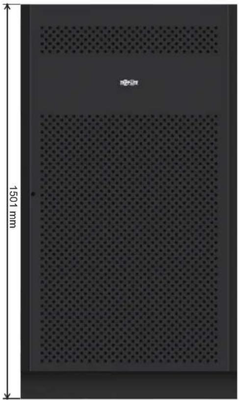
Battery Cabinet Dimensions
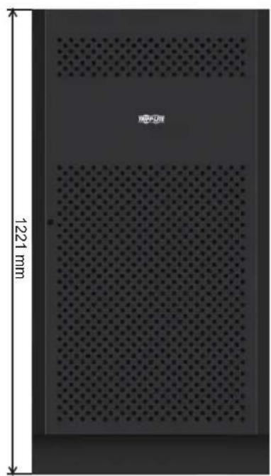
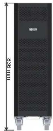
12V 9/10Ah x 80pcs12V 40Ah x 40pcs1
| Battery Cabinet Models | Breaker Included | Dimensions (H x W x D) mm Description | |
| BP480V100 | 400A, 3-Pole | 1501 x 826 x 1136 | Battery Cabinet with 40 x 100Ah batteries |
| BP480V100-NIB | Battery Cabinet without batteries, but designed for 40 x 100Ah batteries (includes battery cabling and breaker) | ||
| BP480V65 | 300A, 3-Pole | Battery Cabinet with 40 x 65Ah batteries | |
| BP480V65-NIB | Battery Cabinet without batteries, but designed for 40 x 65Ah batteries (includes battery cabling and breaker) | ||
| BP480V40 | 200A, 3-Pole 1221 x 826 x 900 | 826 x 900 | Battery Cabinet with 40 x 40Ah batteries |
| BP480V40-NIB | Battery Cabinet without batteries, but designed for 40 x 40Ah batteries (includes battery cabling and breaker) | ||
| BP480V10 | with 80 x 9Ah batteries Fuse, 100 Amps 836 x 250 x 779 | 826 x 900 | Battery Cabinet with 80 x 10Ah batteries |
| BP480V09 Battery Cabinet | |||
| BP480V10-NIB | Battery Cabinet without batteries, but designed for 80 x 10Ah/9Ah batteries (includes battery cabling and fuse) | ||
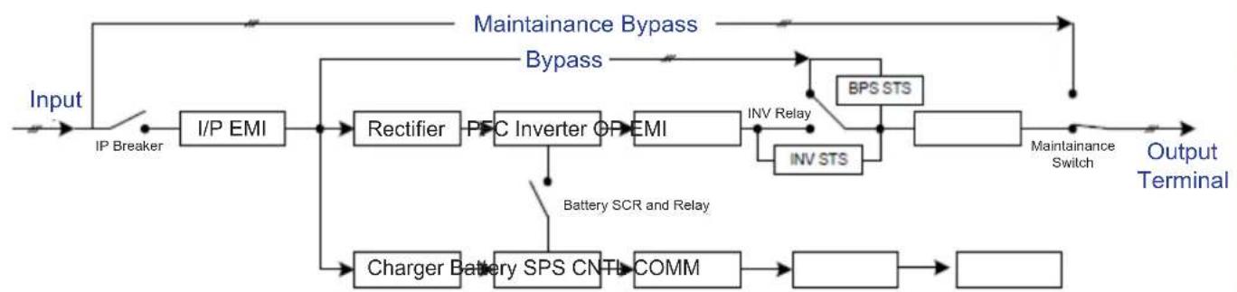
UPS Functional Block Diagram
9. Warranty
Your SmartOnline 3-Phase UPS System is covered by the limited warranty described below. Extended warranty (3- and 4-year) and start-up service programs are available. For more information, call Tripp Lite Customer Service at +1.773.869.1234 or visit www.triplite.com/support.
3-Phase UPS System Limited Warranty
Seller warrants this product, if used in accordance with all applicable instructions as verified by Tripp Lite's "Start-up" service, to be free from original defects in material and workmanship for a period of two (2) years from the date of start-up. If the product should prove defective in material or workmanship within that period, Seller will repair or replace the defective parts without charge for labor or parts. If the product was not started up by authorised Tripp Lite service, replacement parts will be provided but labor charges will apply based on published Tripp Lite Time and Material Rates. Tripp Lite will assign to you any warranties provided by the manufacturers of components of the Tripp Lite product. Tripp Lite makes no representations as to the extent of these warranties and assumes no responsibility for warranties of these components. Service under this Warranty can only be obtained by contacting: Tripp Lite Customer Service; 1111 W. 35th Street; Chicago IL 60609; +1.773.869.1234; intlservice@triplite.com.
THIS WARRANTY DOES NOT APPLY TO NORMAL WEAR OR TO DAMAGE RESULTING FROM ACCIDENT, IMPROPER INSTALLATION, MISUSE, ABUSE OR NEGLECT. SELLER MAKES NO EXPRESS WARRANTY OTHER THAN THE WARRANTY EXPRESSLY SET FORTH HEREIN. EXCEPT TO THE EXTENT PROHIBITED BY APPLICABLE LAW, ALL IMPLIED WARRANTYES, INCLUDING ALL WARRANTYES OF MERCHANTABILITY OR FITNESS, ARE LIMITED IN DURATION TO THE WARRANTY PERIOD SET FORTH ABOVE; AND THIS WARRANTY EXPRESSLY EXCUSES ALL INCIDENTAL AND CONSEQUENTIAL DAMAGES. (Some states do not allow limitations on how long an implied warranty lasts, and some states do not allow the exclusion or limitation of incidental or consequential damages, so the above limitations or exclusions may not apply to you. This Warranty gives you specific legal rights, and you may have other rights which vary from jurisdiction to jurisdiction).
Regulatory Compliance Identification Numbers
For the purpose of regulatory compliance certifications and identification, your Tripp Lite product has been assigned a unique series number. The series number can be found on the product nameplate label, along with all required approval markings and information. When requesting compliance information for this product, always refer to the series number. The series number should not be confused with the marketing name or model number of the product.
WEEE Compliance Information for Tripp Lite Customers and Recyclers (European Union)

Under the Waste Electrical and Electronic Equipment (WEEE) Directive and implementing regulations, when customers buy new electrical and electronic equipment from Tripp Lite they are entitled to:
- Send old equipment for recycling on a one-for-one, like-for-like basis (this varies depending on the country)
- Send the new equipment back for recycling when this ultimately becomes waste
Tripp Lite has a policy of continuous improvement. Specifications are subject to change without notice.


1111 W. 35th Street, Chicago, IL 60609 USA · www.triplite.com/support
Modelos: S3M30KX, S3M30KX-NIB, S3M40KX, S3M40KX-NIB, S3M60KX, S3M80KX
Entrada: 220V / 230V / 240V (Fase - Neutro) 380V / 400V / 415V (Fase - Fase), 30 4 Hilos + Tierra Física
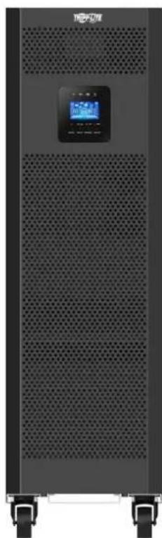


1111 W. 35th Street, Chicago, IL 60609 EE. UU. • www.triplite.com/support
Articulos necessities:
2.5 Preparation 109
2.6 Installation 109
2.7 Avertissements concernant la conexion 109
PykoBODCTBO N0Ib30BaTeJia
Mодени: S3M30KX, S3M30KX-NIB, S3M40KX, S3M40KX-NIB, S3M60KX, S3M80KX
BxOJHoe nHTaHHe: 220/230/240 B (Φ.-H.), 380/400/415 B (Φ.-Φ.), 3-Φa3Hoe, 4 npoBoda + 33
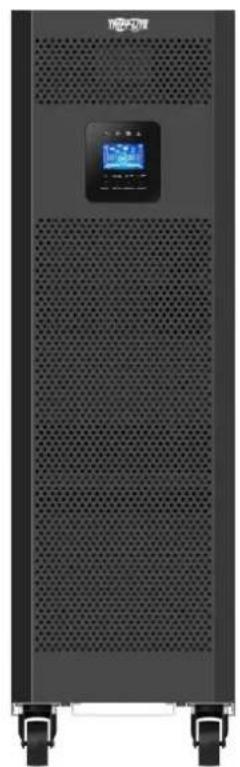
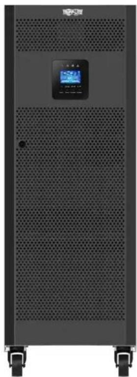
EAC


Ptoyusu muhuru
CopepxaHne
1. BBeDHe 159
2. Baxkhble npedynpekdeHn no texhke 6e3onachoctn 160
2.1 Ppdpynpejckdne HOTocHTeBn MeCtpa3MeuHn N5P 160
2.2 PpeynpckdEHHN OTHOCHTeBHO NOKJIQUeHnO6OpyDObaHn 160
2.3IpeDyPnpeKdEHHaOTHcHTeBHo 6aTaapei 160
2.4 TpAnCnpTIpOBka HxpaHeHne 161
2.5 IoproToBka 161
2.6 yctahOBka 161
2.7 Ppeynpckdennr OTHocuTeBn noKnIOUcHenn 161
2.8 3Kcnnyataa 162
2.9 CoOTBETCTBME CTAnDapTAM 162
3. YctaHOBKa n HacTpoiKa 163
3.1 PaCnakOBka HOCMOtp 163
3.2 IopraoknoKIOJIueHnBHyTpeHHx6aTaapeiNoM.S3M30KX,S3M40KIX,S3M60KXuS3M80KX
3.3 YctaHOBKa BHyTpeHHIX 6aTapeB Moedex S3M30KX-NIB u S3M40KX-NIB
3.4 YctaHOBKa OdHHOHTo IVbI 178
3.5 YCTAHOBKa IB B CNTeMax c npaJIeBbHbIM noJKnIOUeHHem 180
3.6Поdkлочиь Всшпь 6batpei 181
4. Iopraok 3Kcnnyatau 182
4.1PnHnIeCTBna KhoNOKnCnner 182
4.2 CbToIIOHbIe HNdkaTOpbl NKK-panHeB 182
4.3 3bykoBaaCnHaHnaaiaa 184
4.4 Popdoekkncnyataun OndnoHOrO 184
4.5Iopraok3KcIpyataunnapaIIeNbHO noKnIOueHbIX N1 186
4.6PaCunHΦpOBAa66peBnAtypHaKK-dncnnee 188
4.7 MeHIO Setup (Haayalbna yctaHOBKa) 188
4.8 Oncanhe paoboux pejmmOB/coctoHH 194
4.9 Koblennopabnoctei 200
4.10 ⅢnDikatop npedynpeckdeHua 201
4.11 Koidby npdeynpexkdeHn 201
5. CpeCTBa B3aImoJeCTBn 202
5.1 Pa3beM dIy IIOKJIIOUeHnIgSNMP-KapTbI 202
5.2 Pa3beM EPO 202
5.3 Iopr RS-232 202
5.4 Ioprt USB 202
6. BbIaBHeHne uYcTaPaeHne HncnpaBHoCTe 203
7. XpahenHe n TexHnueckoe o6cIyXmbaHne 204
7.1 XpaheHne
204
7.2 Texnueckoe obcnykBaHne 204
7.3 Batape
204
7.4 BeHTWIJATOP
204
8. Texhueckne xapaKtepncn 205
9. TapaHTnHbIe 06a3aTeJbCTBa 208
English 1
Espanol 53
Français 105
Deutsch 173
1.Вててん
Bbmyckaembl kcmnnaHm Tripp Lite nctouhN 6ecnepeboHoro NHTAHM (MBI) cepnn SmartOnlin S3MKX npedctabnAeT co60 he3aBNCMbY OT HapraeHHN HACTOTb Tpexpa3HBn OH-aiH IN BICDBoHIM pno6baOBAHEM. 3TOI bIN HnpepbIBHO CTABNI3HPyET BXoHDoe 3EKeTPWCEKOE NHTAHME, YCTPAHRA TEM CAMBIM HApUeHHN PEXHM PAITAHN, KOTOpBIE B npotmbHom Cnyue aPiBOdJIb6bl K BbIXOHy I3 CTPOA YCBCTBNTelbHbIX 3JeKTPoHHbIX yCTPOICTB, IN CBODA K MHNMYM DINTELBHOCTB IpocTeOB, BB3bIAEBHX KOIE6AHMRMM MOUHOCTN IN nepe6oMM BHEPROCHA6KeHHM.
MoJIeN I6I cepn S3MKX CKOHCTpynpoBaHb C BoTBeCTBm C blycoaHIMC TAnDaPTAMM KaueCTBa N pOOn3BOJNTeHbHOCTN IOECEneMBAOT CteJeYIOUe BO3MOXHOCTN:
| Моdensь Агентский Homeр Мошисть | |
| S3M30KX AG-6030 30 кВА | |
| S3M30KX -NIB | AG-6031 30 кВА |
| S3M40KX AG-6040 40 кВА | |
| S3M40KX -NIB | AG-6041 40 кВА |
| S3M60KX AG-6060 60 кВА | |
| S3M80KX AG-6080 80 кВА |
- OH-naiH IVI - Bicocayamn ypoBeHb 3aunHb IVI c nonHbIM KOHTponEM BXOHDHO 3JIeKTPoNTAHN HnyEbbIM BpeMeHem NepeKIOHeHn Ha nITahne O t bapeB CNYae DInTeBHorO OTKNIOUeHn CTeBOrO 3JIeKTPuueCTBa CcIeBIO HENpepbIBHO IOIDepXHa npAOToCnOC6HOCTKnPHTueCKn BaXhBx NOTpe6nteH
Bo3m0kHocb npapannelbHoro noknouenHn do tpxn mC p cienb ybeunueHn Bbxxohn moaHcTn
BbIcOKM KITB pexKIMAX nHTaHnO tCeTH npeMeHHORo TOKa m pe3epBHorO nHTaHnO oTbapei
MHHMaHbHa 3aHmMaemn plouaDb cpei BceX ppeCTabHeHHbx Ha pbHke aHaoROB, yTO o6ecneuBaet Bo3MoKHOCTb yBeHNueHn MoOHTn npn yMeHbWeHn Tpe6yEmo npocTpaHCTBa
Pekn ECO 030BnAet IBIyHKUHNPoBaT no 06xOHOH CEIN B yCIOBNAx yCTOuHBORO cTeBOrO nHTAHN I oecneuHBAET HeMeJeHHoe nepeKLIueHHe B peKIM ppeOp3oBaTeJn DnnoepKaHnpaobTOcNOc6HOCTnNotpebnteneB Cnuyae nae HnnpaMetPOB BXODHO rTOEBOrO nHTAHN Hnke DoNYCTMNBIX npdeNoB
BbocnKo30HmHbMoHcTn-108bHeHnAe00EaHnBaHnMoHcHt bOecneHnBaet noDpeXnHaMe pa6oToCnO6HocTn 60bnwero cKnKaOMnoHentOB 60byDaHn - ABOMatueckm npuynoepexoHa o6xohnyu cenb B uejnx noBliueHn HadeKHOCTn CHTeMbI N o6ecneueHn BO3MOXHOCTn TEXHueCKOrO 6cnykBaHn 6e3 ChrTn MOUHOCTn C nokKnUoyehHoHarpy3kn
IINpOKm dnaa3oB xOaNbHn HapJxHn - 5Nl o6ceuMBAe terpynnpoBaHne npametpoB xOHDoro 3NeKtpOnTAnH daXe npn nIOXOM kayctBe nocJeHero 6e3 nepeXoHa naTahHe O batape, YTO CNOcO6CTBye TAKCIMMaBbHOmy yBENueHNO BPEMeHn 6e30Ka3HO npaObTu N KOHOmmpeycpa 6aTaep
CObMEcMoCTb CBeHsHIMM 6aTaepHbIMn 6kaΦaMn 0eCneuMbAeT NOBbIeHne CTeNEH aBOTHOMHOCTH 6aTaep - AbapinHoe OTKJIOUeHHe NITAHM INCTAHUMBHm CNOcO6OM (REPO)
- Bo3MOxHcOHTnKoHTPOJI npaMeTPOB cTeI N CTeBOrO ynpBaJIeHNI PO npoToKoJy SNMP cNcIObTOBaHmE ynpBaJIrHOuXkAPr "CyHX" KOHTaKToB
IbCepnSmartOnineS3MKXueaJIbHOIOxOaTdna3auntbKpUtnMecknBaxHOrOeNtpo06OpDobAHn,ncnlo3yemoroBcoCTabe:
- MT-nHΦpactpykTpybl
TeKOMMyHnKaUHOHOro 6OpyDobAHm - cTei (JIBC/TBC)
obkeTOBoprAunH3aunHOHHnOphactpykTpybl
CnCTEm 6e3oNaCHOTH N abapMHbIX CNTcEM
JERKNX pOmbiHJIeHHbIX yCTaHOBOK - mHaHcOBbIyUpeXeHnH
2. Baxhblie npedynpejckdneHn no texHnke 6e30naCHOCTN
COXPAHNTHE HACTOUIE YKA3AHNA
B hactoIe m pykoOCTBe cOepKata BaxKbIe yka3aHn I npEynpeJdeHn, KOtObIe He6xOJMo CO6NIOaTb B npoceCe yCTAHOBKn TExNHueckoro 06cnyhBaHnB Cex Txepa3hX IV5Pi Tripp Lite cepHH SmartOnline S3MX moocctb1o 30, 40, 60 u 80 KBA nix 6aTapei. HrhopnpobHne 3THx npEynpeJdeHn MoKet npHBecn K notepe rapaHTnn.
2.1IpeynpexkdeHnOTHocntbHo MeCTa pa3meuen H6Pi
- YctaHabIMBaTe WbI B3akpbTOM NmoeUeHHn BdJIOnOT hCtOuHKnOB H36bIToOHn BnAri nNn Tena, 3JeKTpnpoBODhBx 3aRpa3HnTeJe, a TaKKe npAMoro cONHeuHOro CBeta.
- YctaHabimbaite N5Pi B KOHCTpyKunOHn IpoHOM MeTe. N5Pi ABnEeTc KpaIHe TKeJeIOBeChbIM, NoTOMy PnI erO npemeeHH N IOBbeMe Heo6xOJMo c6NIOaTb oc6yo OCTOp0XHOCTb.
3KcnnyaTnpyIe N5I TOnbko npn KOMHaTHbIX TemNepaTpax (B dana3OHe o 0 do 40^ - Otnmamnbna npn3boaHtebHObctb N5n MaKcmaIbHbCpOK cnyX6bl 6aTapeN doCTVaHOTc npn noDepxAHn pa6oey TeMnpaTybpB Dnana3OHe ot 17do 25^
06ecnebye B mece yctahOBKn DOCTAOHoe pOcTpaHCTBO IaI TeXHueCKoro 06CnyKbAHn H BeHTINaunu INP. Pa3mep npocTpaHCTBa Ira TeXHueCKoro 06CnyKbAHn H BeHTINaunu DIOJIKeH COCTABNtB He MeHee 50 cm CTbInbHO, NmueBoH IO6EH 60Kobix CTOPOH INP.
He yctahabmbai Te 15106n3m MaHHTbIX HOCITENE INHOPMaUN, NOKOJIbky To MOKeT pNMBcTn K HApUSeHNIO cENoCTHO XpAraHuaXcRA HnHaHHbIX.
2.2IpeynpexdHnOTHoTebHOIOKIOeHnO6OpydoBaHn
He peKoMeHnyetca HcnoIb3ObaHnE daHnHO o6OpuyoBaHnB CnCTeMax KIn3Heo6ecneHnE, Ige erO bIXoN 13 CTPO npEaIIOXHTeBHO MoKeT pNBecTM K nepe6oAM B pa60Te o6OpuyoBaHn Jx3Heo6ecneHn HnB 3HaHTeNbHoMpe CHuNTb erO 6e3oNaChOCTb HnI eFKeTMBHOCTb.
- 1651 MmeeB CooCTabe Co6CTBeHHbI HcTOOHK 3Heprn (6aTaepo). BbIXOHBie 3axHMBy UcTpoiCTBa MorY T haoMTbc NOD HanpaKeHNem Daxe Nocne OTKnIOUeHNy UcTpoiCTBa O T cTeN nepemeHHoro ToKa.
2.3IpeynpexdHnOTHocHTelbHo6aTapei
MbI cOeJXMT Bce6e KOMnoHEnbI, HaxoJauneocn oN HAPRJEHEHM, OITACHbIM IJI JxN3H. IBI paccunTah Ha noauy neKtponntaHnNotpe6ntam daKe npu otKnIOueHNOTcEBORIO hTOUHnka. DocTyBHytpb Kopnyca IBI pa3pe7aetc TaIbko YIOJIHOMOUEHHbIM CIEUAAINCTAM IIO TEXHnECKOMY OBCLYXMBAHHO nocne otKIOueHNy UcpoCTBAOTcEHn HTOUHnka NHTAHNA NOCTOHNO TOKA.
5bataepu Hecyt B ceb6 oanaocctb 3neKtpueckoro ynapa n noyueHHN OXOROB NOB IOB3dEChTBnEM CnHBOrTO KOKOTKO 3aMbKAHN. IIOKNIOUeHMe NIN 3aMeHa 6bapeu DOnJHKbO cyseCTbA TcTbKO KBaHnHnipoBaHHBM cepBnCHBM NepcoHAnOM C COBIOeHMe HADNEKaHm Mep npEOCTOPOXHOCTN. BIKIOuaTe NIPpeNIOKNIOUeHMe INN OTKnIOUeHMe BNYtEHNN 6bataepu. NcnoB3yIte HNCTpyMeHbI C 30JIIOpOBaHHBM pykAMn. He BCKpbBaIte 6bataepu. He 3aMbkaIte N He 8yHTnpYte KJIEMMbI 6bataepu KaKMnHn6o npEpmetamn.
Bataep npiroDbI Ia BTOpHNO nepepa60Km. MeCThIE HOpMaTBBI IN Tpe6oBAHn NO yTNIN3aun NIO6 pyKOBOCTByTEcB INHOpMaueH No yTNIN3aun HA Be6-CTpaHnue http://www.triplite.com/support/recycling-program.
He 6pocaiTe 6atapeuB orOHB, He donyckaiTe Hx nobpejckdHn Hne BCKpbBaIe Mx o6mbky. BbiteKaIOUm N3 Hnx 3JIeKtpoIT M0KeT RJIaTbC TOKCNHybIM N Bbl3bIbA Tb npaKeHn KOKN m cIN3cTOJ O6OOnQkRr3.
HeOTcoeIMHnIe6bATEBBOBPbEMpa60bIbPbE9MmEHTAHN0T6bATEH.
- OToeDnHnIte HCTOuHnK 3aepdHOrTO TOKa DO NIOcOeDnHEHnN INIOToCeoDnHEHn3aJHMOB.
- Heo6xoJIMO co6bIOnHeHne cIeMyOuHX Mep npEocToPOKHOCTN:
1) Npep a6b0r ChnmaTe Cc6e HapuHbte HaCbI, KOnbua n DpyHe MeTaNlueckMe npEmtB.
2) WcnoIb3yIte HnCTpyMeHtB C n30InpoBaHHbIMn pyuKaAM.
3)McnoIb3yItepe3HNOBbIe nepaTknUduNtKeTpueCKeN60Tb.
4)Pnpa6oTe c6aTapeMmNcIOnb3yIte dIeNekTpUeckmpeHNOBbKOBpNK.
5) He KnaIaIte HNCTpyMeHtBi NIM MetaIIINeCKHe DeTaN HA BepXHHe NOBepXHOCTn 6aTapei NIM INx KOpnyCOB.
6) IpoBepBe 6bataeEO (BbIbObl+,-,N) HApEIMET CnyaHHO T3MbKAHNA HA 3emNIO. BcIyae O6hApYKeHHA TAKOBTO YcTpaHInTe HcToHNK 3a3EmHeHH. PnIKoCHOBHeH KJIIOB yactn 3a3EmHeHNO 6batae MoKet npBecTN KnpaKeHHIO 3JIeKpueckm TokOM. BepoTHocTB TAKO TnpaKeHH CHIXKaETC pN yCTpaHHeHH 3MbKAHNA HA 3emNIO BO BPem yctahOBKn IN TexHueCKOrO 6cbyKmbAHn.
3aMeHa 6aTapee DnJHnHa PnO3B0DnTcA BTOpN3oBAHHbIM CepBnCHbIM NepCOHaONM CnONb3oBAHNEM 6aTapee aHaIOnrHuHOrTo Tmna (repMeTHuHbIX CBNHIOBO-KMCNOThbIX aKkymyTAOpHbIX 6aTapee) H TOm Xe KOnuYeCTBe.

BHIMAHHE! Bo 36eKAnHe BO3HKnHOBeHn KaKnx-Jn6o OnaChocTe npu yctahOBKe nTexHueckom o6cnykBaHm N5I yka3aHHbte 3aDaun MoryT BblnoHrTaBtbo KBaJIHmUpOBAHbIMn OblITbIMn 3JKeTpOMexAHnKaMn.
IpepeyctahOBKOIMcNpbl30BaHmEm daHHoro yCtpoCTBa BHMAtelbHo m3yHTe HactoJIee pykoBODCTBO nolb3OBATeJMykAaHnnoTexNHKe 630NaCHOTM.
2. Baxhblie npedynpejckdneHn no texHnke 6e30naCHOCTN
2.4 TpaHcnpTnObKa uXpaHeHne
1ДузаштыоударьхиудгхмexaHuecKxBO3dEChTBntpaHcnpTIpOBKaNbDOnkhaocyueCTBnTbCToIbkoB3aBockyoYnaKobke.
XpaenHneIbIOnKHOOcyueCTBnTbCBycXOMHXopoIO npOBetpBaemOMNomeeHm.
2.5IoprotoBka
B Cnyae HnncpeCTBeHHOro nepemeeHnH 15I n3 xnoJHO B TcNpy cpey moKet Bo3HnKaT KoHeHcaun. Npea yctahOBKO I6I Heo6xOIMo DaTb emy Bo3MOXHOCTb noHoc7b npcoxHyt. DaIte I6I B03MOxHOCTb aadtnpObaTcR K HOBO cpee B TeueHne Ka MmHymM dByx Acob.
He yctanaabnbaite HbBn3n BDObln BlaJhbX cpe.
He yctahabnbae Te NIOI pRMAbIM COINHEHbIM CBTOM HN B6mN MTOCHYNKOB TELJIa.
He 3aropaxmbaTe BENTHnauMOHHbE OTBepCTMa Bkopnyce IVI.
2.6YCTaHOBka
He nooknouaTe K bixoHbIM po3eKAM mnn 3axkumm HbPi np6opbl mnn yctpoCTBa, KOtOpe MoRn 6bl Bb3bIbAteB er opeperpy3ky (t.e. o6OpyDobAHme C moUHbIM 3neKTPOBBArTaJIHM).
06ecneuHaiBe aKkpyaPHTy pOkoJaNky Ka6eJe, cTeM qTo6bI HNkTO He MoR Ha HnXHaCTynTb HIN CNOTKNYbC O HmX.
He 3a0rpaKbAte BENTnIaHIOHbte OTEBepCTNBA KOpTyne IBII. IBI DOnJIeH yCTaHABINBaTcB XopoIo npOBETPbAmOM NOMEeHH. Co BCEX CTOpOH yCTpOHTBA Heo6xOIMMO oecneuHb DoCTaTOUHO CBO6OHDoro nOpcTaHCTBA dJeero HADNeJauCero npOBETPbAHm.
Ha Kopnyce 16Pi HmeeTcra3aemEnHbKOHTAK. B OKOHaTeJIbHOYCTAHOBouHO KoHpyruaCmCTeMb Heo6xoIMMo 06cneHTb 3KBnnotHeuJbHOe 3aemHne Upe3 BHeuHm 6ataepHHbI KAF I6Pi, CoedINH Mekdy cOob 3aemHIOUme 3aKMMbO 60nx kkaOFB.
YCTAHOBKa IbI pOJIKH pON3BOIMTcBcra TObko KBaIIHpUcPOBaHHbIMn 3eKtpoTeHNkAMN.
Pn moHTaKe 3eKToPOnpOBoDkn B 3dAnHn DOnJHo npEycMatpBaTbCra HauuHne yctPoTcBA 3aunTHoro OTKnUoHHe HanoOpMo pe3epBHO 3aunTbOT KOPOTKO 3aMbKaHN.
Kpome toro, npBbINonHeHH 3JektpomOHtAkhbIX paobT B3dAHm CnCTema 3JektpopOBdoKn DOJIKH aOCHAaTcBCTpoEHbIM N30IInpOBaHbIM yCTpoCTBOM ABAPMHOROTKNIUeHH.
IIOKNIUOeHHe K CNTeMe 3a3eMJIeHn JOJNKeHO 6bTb BbIPOJIeHc DO IOKNIUOeHn KMOHTaXHbM 3aXHMAM CHTeMbI JETKpnpoBOkM 3dAHn.
3NeKTpOMHOJXHbI paOToI dONXHbI pOnI3BOIDtCBa COOTBETCTBm C MecTHbIMN 3NEKPToEHXHueCKHMn HOpMaMn I npabnAM.
2.7IpeynpeKdHnO tHOcnTeNbHO nOdkNoeHn
BHTPENHRA KOHTpyuNIAIbI NepeyCMATPNBaET HnWnIcTaNAPTHO3aIHTbIOTo6paTHbIXTOKOB.I30IpyTe I5IdoHaayana pa60tB TAKOIeKTPueckoi cem. 10Ipyooee yctpoiCTBOIOJXHO6bITpaccunHtoHa npOnycKaHBExOHOToKa I5I.
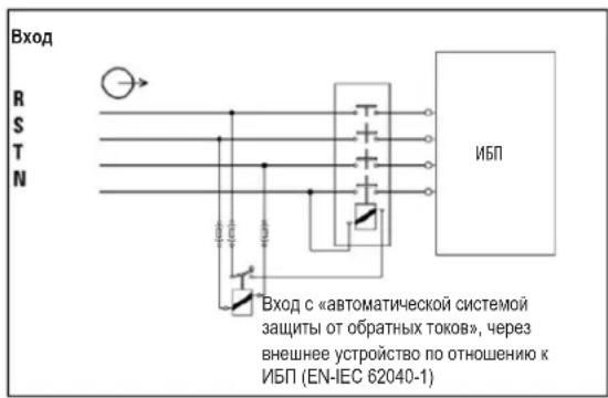
-ПоdkнluчehmeДан HorO IbI DoJnKho IpoU3BODuTbCЯ CInOJIb3OBAHmE mCtEmbl 3a3eMneHnTN.
Ic0uHm3eKtpOnHAnHa daHnO roy cTpoCTBa doNKeH 6bIt bpexpa3HbIM HMeTb HOMHaBhble npaMeTpbl, COOTBeCTByoune yka3AHbIM Ha 3abOcko Ta6nUke o6OpdyobAH. Kpome toro, OHdoNKeH 6bIt bHaNeXaUIM 6op3OM 3a3EmHe.
Bo Bxodnoi eHn n HtAHm Tpexfoa3hBx MoJeIeN IbI Heo6xoJIMo HAIuHne 4-NonIOCHOro ABToMaTHueCKOrO BbIKIOuTeHa.
Hepekomehyetcncnlo30baHne daHHoro 6opuyoBaHm B CNTeMax Kn3HeoeceeneHH, Ige erO bXIOI N3 CTPO npeDnnoKHTBHO MOKET npNBecT K nepe6oAM B pa6ote 6opuyoBaHm Kn3HeoeceeneHH IN B 3HaHTeHbHO Mepe CHNtB er63onacHOCTb Hn eFekTMBHOCTb.
- Pnokknoe Kneemmy 3aemnene HmnoBOrMoyn M5N K npOboy 3aemnhoero 3neKtpoJa.
- I5I pnoKlnoueH K nctOuHnky 3Heprnn nocToaHHoro ToKa (6aTaapee). BbIXoHbIe 3axmmby yCTpoiCTBa MoTy OCTaBaTcN oN HapPaeHHem DaXe noCJe OTKnIOueHHa YCTpoiCTBa O T cTeN pepeHHoro ToKa.
2. Baxhblie npedynpejdeHnnoTexnke 6e30nacHOCTN

Pn yctaHOBKe yCTpOeTBA npOeBpe, 406bI nCnol3yeMa naHeIpeMOTHoro 6aIIaca (He3aBcIMMo OT ee TINa) 6blHa HAcTpoEHa HAdJIeKaUIM oBa3OM Do NODaH NITAHN Ha yCTpOeCTBO.
Bce n3oIaTobpO bocOBHoro nctOuyHnKa nHaTHy, yCTaHbAINBaEMbIe Ha ydaIeHM OT MeTa pa3MeueHHN I6Pi, a TAKKe IIObIe ToCK NIOCTyNa MekNy TaKIMN 30JIaTOpaMn IN6Pi dONKHB CHa6KaTcPneDynpTeiBbHMn HAcKeIaKMn. PpeDynpTeiBbHn HAcKeIa DOnJkHa IMTeKCT CNeDyUoero Nm PAbHOzHaHOrO coepKaHn.
Ipea n aon paobb I daHHo 3eKtpuecko cnn:
N30nnpoBAtb NCTOCHK6cnepeboHOro nHTaHa(N5I)
-3aTeM npOBepuB Bo3MOxHoe HauNue OaCHOrO IaI K3Hn HauPaeHeHH MekDy IIO6bIMu 3aKImMaMn, BKNUcA 3aKIM 3aUNTHo 3aEMNeHn.

Onachoctb obpaTHoro HanpJxehnla!
2.83Kcnnyataua
HmB KOEM Cnyuae He OTKNOUaHTe Kaebb 3aemlenHnO NT5N HIN 3aXMMOB CNTcEmbl 3NEKTPonpOBOKn 3daHn, NocKNbky 3TO pNMBET K NOtepe 3aunTHoro 3aemHnH N5N.
A JINHOIOTKIOUeHnHbI ChaJala HAKMITE Ha KONKY BbIKIOeHnH ("OFF"), a3aTeOM OTKIOUHTe eO O TJIeKTPueckOn cTeN.
NCKHOUHTBEO3MOXHOCTBnonaHaHnKaKHX-Jn6oJHKOCTeHNnNOCTOPOHNXnpEIMTOB BNYtpb Kopnyca N5P.
2.9 CoOTBeTCTBnE cTaHApTAm
22) YctahOBtHe Ha CBOM MeCTa KPOHHTeHbI DnA KpePHeHb6aTape.
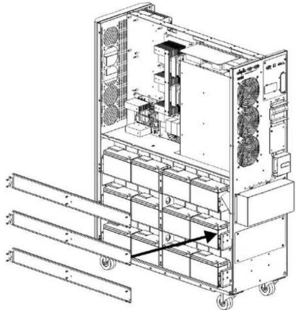

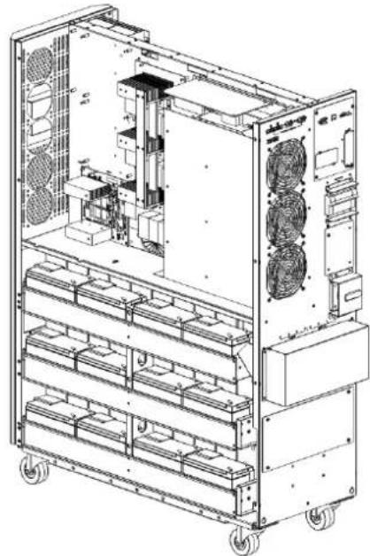
3.YctahOBka nHaCTpoiKa
23)MnObl3yBONbTMepT,H3MePbTe pa3HOCTb NOTEHuaNOB MEXdy NOnOXHTNBHbIM NOIocOM 6aTapeu No20NOTpuAteINbHbIM NOIocOM 6aTaapeu No1.(HapxKeHne NOCToHHOrTOkA DINOJHXHO HAOHTBCB DInaHa3OHe 240-270 B)

24)NcnoB3y BONbTMepT, H3Mpe Ta3HOCTb NoteHuaNoB MekJy NonoKHTbHBIM NOIocOM 6atape N#40N OTpuateNBbIM NIOOCOM 6atape N#21.(HanpKeHne NOCTOHHORTO TOKA DOnjHo HaxoNTbCB B DnHaPAn3OHe 240-270 B)
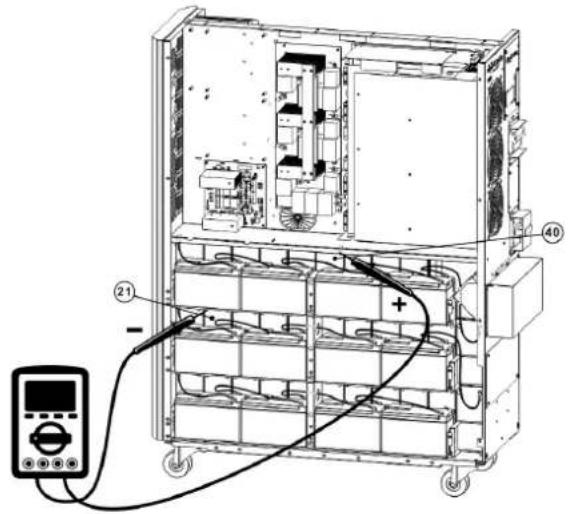
25) MIOJIb3yB OJIbTMeTp, I3MEpIe pa3HOCTb POIEHuaNoB MEXKdy NIOJOHTeJIbHbIM NIOJOCOM 6aTapeN ^#80 n OTpuATeJIbHbIM NIOJOCM 6aTapeN ^#61 . (HapJKeHHe NOCTOHHOrTo Ka DOJXHO HAXoDITcB G dIana3OHe 240-270 B)
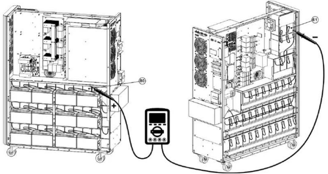
26) MIOJIb3yB OJIbTMepr, I3MEpIe pa3HOCTb POIEHuaIOB MEKdy NIOJOHTeJIbHbIM NIOIOCOM 6aTapeu N°60 n OTPiauTeJIbHbIM NIOIOCOM 6aTapeu N°41. (HaipJKeHHe NOCTOHHORo ToKa DOJIKHO HAXOJDcB C DmaNa3OHe 240-270 B)
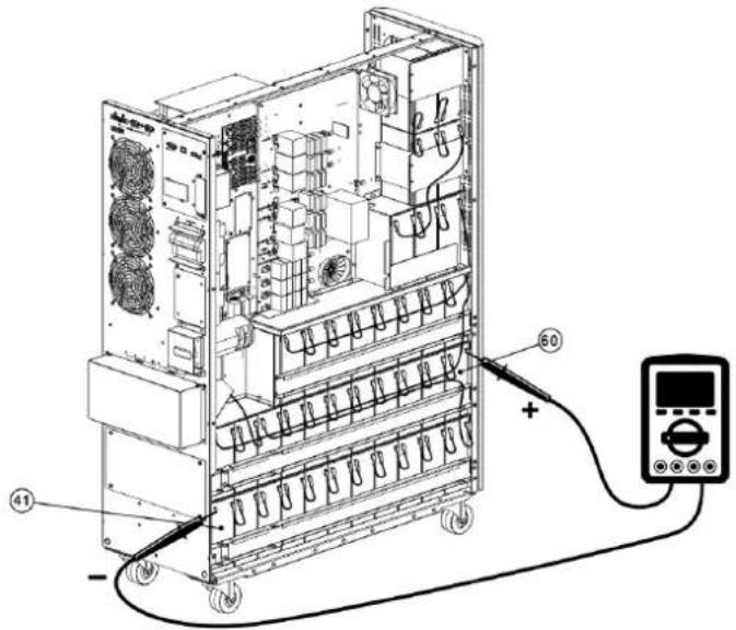
3. YctaHOBKa N HacTpoiKa
27) ⅡIa coeHHeHHa 6aTaape Hcnoh3yTe nnaTy npdoxpaHntene, a TaKKe c.m. pnc. 3.5, 3.6 n 3.7. IOnHbI cIncoK coeHHeHH mExdy 6aTapeHHnnpctTabneB Ta6nue 3.1.
TaBnua 3.4 Batapeu n ABToMaTHueckHe BbIKNoUaTeN dJa 6BaTapeHOrO WkaΦa
| Моdenь | Батуени вkomплеске | Номинальна мошносты колочецвбтуарей | HOMINALY ABOTMAUTHOCKORO BVIKLOUATELA |
| BP480V100 | Да | 100 A-ч x 40 sm. 400 A, 3-noюнchy | |
| BP480V65 65 A-ч x 40 sm. 300 A, 3-noюнchy | |||
| BP480V40 40 A-ч x 40 sm. 200 A, 3-noюнchy | |||
| BP480V100-NIB | 300 A, 3-noюнchy | (Passchütан ha) 100 A-ч x 40 sm. 400 A, 3-noюнchy | |
| BP480V65-NIB (Passchütан ha) 65 A-ч x 40 sm. | |||
| BP480V40-NIB (Passchütан ha) 40 A-ч x 40 sm. | 200 A, 3-noюнchy | ||
| BP480V10 | Дa | 10 A-ч x 80 sm. 100 A (празханитерь) | |
| BP480V09 9 A-ч x 80 sm. 100 A (празханитерь) | |||
| BP480V10-NIB | Het | (Passchütан ha) 10/9 A-ч x 80 sm. | 100 A (празханитерь) |
PnmeaHn:
Ka6enb mO. S3M30KX dONJKeH bIepeKxBaTb ToK 6onee 63 A. B cenax noBbIeHn yPobHe 6eOnaCHOCTn KII peKOMEnyETc HcNolb3OBaTb npoBo n KaH6pa 8 AWG (8 MM) nHn TOnue da Pa3 n KaH6pa 4 AWG (21 MM) nHn TOnue dnn HeHtpani.
Ka6eBnMnO.53M40KXJIOJKeH BbIepKHeBaTb TOK 60nee 80 A.BueaX noBbIeHna ypoBHe 6eOnacHocTH IN KIIpeKoMeHnyeTcNtIb30aTb PpOBD KaH6pa 6 AWG (13 MM) HIN TOnIe DnA pa3 u KaH6pa4 AWG (21 MM) HIN TOnIe DnA HeITpani.
Ka6enb mO.53M60KX dONJxH BbIepKHBaT bok 6oee 122 A. B cENHX NOBbIeHn yPobHe 6eONaCHOCTN KIIpeKOMEHyETc HcNtB3OBaTb npOBoKanHpa4 AWG (21 MM) Hm TOnIe dAn pa3 n KaHbpa 1 AWG (42 MM) Hm TOnIe dAn HeHTpAHI.
Ka6enb mO.53M80KX dOJKeH bIepeKHBaBt ToK 6oone 160 A. B cIeR X NOBHe HyaPobHe 6eOanacOCTn H KII peKOMeHnyetc HcNoB3OBaBt npoBd KaN6pa 2 AWG (34 MM²) HIN TOnIe DnA pa3 H KaN6pa 1/0 AWG (54 MM²) HIN TOnIe DnA HeYpTaH.
5) CHMNTe KpbIbky 6noka 3aXMMOB, 3a KOTOpO paCnONARaTcBxOJHbE, BbXoJHbE H 3aEMmIOUme 3axmmbI MII. 3aTEM NOcEOHInTe npobOda cornacHO CXME 6noka 3axmmOB, PpndTabNEHHOHne. IpPOBa 3a3EmHeHmDOnKbHbNIOcEOHHTBCpaHbE DpyTHNpOBOOB.
Приимechан:
YbEHTecB HAdEeKHOITNOKJIIOHENIPOBOIOB K3AJKMMIMNIOTHOCTN KOHTAKTOB.
YCTAHOBHTB BIXOHN BIKNIOATeJIb MEKJy BIXOINHIM 3AXMOM HARpy3KO. BIKNIOATeJIb DOJOKHE COOTBETCBOBaT bYCTAHOBNEHBM Tpe6oBAHHM BOTHOJIH NHYKLIIM 3aHTMTIOT OOPaTHBXTOKOB
Kaebn DOnJXHb6bIb 3aunuHbI rKMM Kaeb-b-KaHAnMa n npoxOHTb uepe3 COOTBcTByUOHe Bbl6HbIe OTBepCTHa B KpbIke 60ka 3xHMOB.
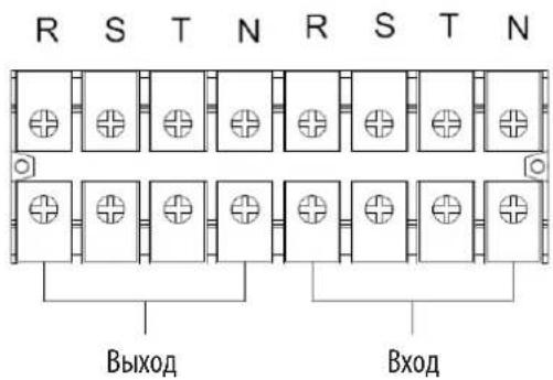
MOthaxnAcxema6Ioka3aKmOBIaMnS3M30KXs3M40KX
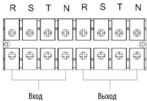
MOHTaXHAR CXEMA 6nOKa3aXIMOB Dn MOJ. S3M60KX n S3M80KX
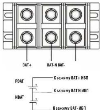
CoeHHTeBna npoBoka 6aTaepn H±240 B
Pnme Hne Kpme TOr, NbN BHeHne 6aTapeHbIe 7kafo DIOJIckHbIbTbO bOra3TeBHO COeIHHeHbIPOB0DM 3auWTHoro ypaBHHBaHMA IOTeHNaIOB.
6) yctahOBHTe KpbIuKy 6noka 3aKIMMOB 06paTHo Ha 3aHIOHO naHeJIb I5II.
3.YctaHOBKa nHaCTpoiKa

BHUMAHVE!
Ipea yctahOBko NbIy6eHtEcB TOM, yTo OH He BkIOueH. BkIOueHne NbI MoKet npOn3BOuTbc TaIbKO nOcne BblONHeHHn H npOBepKn BceX 3NeKTpuCeKN NoKIOUeHN.

BHIMAHVEI!
B cnyae yctanobkni BheuHero 6noka aKymyTopbix 6atapee BBKIOUaTeNb 6atapen nepeyctahOBKO donKeH 6bitb nepeBeEN B BBKIOUeHHe noJoxHe.
PnmeHne. YctaHOBtBe bIKNcHaeTb6NoKa AkkymyTnOpbHb6TaapeB nnoNoJeHHe "OFF"(BbKJI), noCte yero yCTaHOBt 6nok.
IpnctaHbHOB BHMnAHHe CneDyET 6paTb HA HOMnHaHbHO HAnpXeHHe 6bapeY, Yka3aHHoe Ha 3aHHe NaneN. POnKIOUcHHe 6IOKOB AKKyMnTopbIX 6bapeC HenoOxOaHmHapXeHHe MoXet pNBeCTN K Heo6paTMOMy BixOy IVI IN CTPOJ.
06paHTe npCTaBHe BHMMAHHe Ha MapKINPOBY NIOAHOCTN KneMMHOro 6noka BHeuHHe 6aTapeH N o6ecneYte co6nIOeHne NIOAHOCTN npH e NOKIOUeHH. HnpabInbHoe NOKNIOUeHne MoKET n PmBcTeN K Heo6paTAMOMy BxOdy IV5n3 cTPOA.
y6eHnTeB B npAubnlbHOCT 3aunTHOrO 3aemIeHn. Heo6xmo HeyKoCHteJIbHOe co6IOeHne yctAHOBHeHbIX Tpe6oBaHm B OTHouEHM HOMHaIbHorTo ToKa, Ubeta, NoIOKeHn, nOKNueHn HJekTpOPOBODCTNcNoB3yeMbIX PBOBOB.
YbeneBnBpabInbHOCTN BxOHOH N BixOHOH npoBOKm CETn. HeoXODnma TuaTebnHpa npOBepKa cobIOeHHy CTAHOBBHbIX Tpe6OBaHn B OTHoWHeHHOMHaHbHOrTO Ka, Ubeta, noIOKeHH, noKnIOueHH n 3NeKtponpoBHOCTn HcNoIb3yeMbx npoBOOB. YbeneBnBpabInbHOCTn NOkIIHOeHH npoBOOB R, S, T n N, a TaKke BOTcyTCTBNpyTaHnBu MeKdy HmN HKOPOTKO 3AmkaHH.
3.5 YctahOBKa IVB B CNTeMax c npapannelbHbIM IOpKnIOUeHNEM

BHIMAHVE!
3NeKtpomHOaXHbIpepa60tBdoHNbI pON3BOUHTcB C COOTBeCTBn C MeCTbHM HopMaMn HpaBnAm, a yCTAHOBKa DoNkHa OcyeCTBnTbC TOnbKO KBaHmHpObaHHm CneuaHnCTOM No 3NeKtpoTexHke cornacho HNOKeHHbIM HHXe Yka3aHnM.
EcnIbIcnoB3yetcTOnbKIOIaONHOOH3KcNpyatauMTOMOKHOpOpyCTNb daHHbIpa3dIeINpepeoDHTbKa3dEny 3.7.
1) B cTcTeMaX c npaIeNbHbIM NOKIOUeHMe BO3MOxHa yctAOBka Do tpex NpI. He nbTaIteCB CBA3bIbA Tb pyr C pyrom 6oee Tpe XpI B CnCTeMaX c npaIIeNbHbIM NOKIOUeHMe.
2)YctahOBHTe HnoDKHIOHTe IV5CnOrnaHOyKa3AHm, H3NOKeHHbIM Bpa3dene 3.5.
3) Pn moHTaKe CNTeMbI cnapaIIeBbIM NOKINOHcHMe dInHa BxOHNbIX pOBoBD (R, S, T, N) OJHO rIOJIINHbA bIT paBHO INHHe BXOHNbIX npOBoBD dpYrTO I5N. AnanorHMbIM o6pa3OM, BbxOHNbIE npOBoDA (R, S, T, N) TaKKe DOnKHb IMeTB OINHakOByDmHy. B pOTINBHOM Chyae B BixOHD Harpy3e Bo3HKAet TK He6anaHca.
4) NookHHTe BxOHy npoBky KaKJOrO I5N K0 BxOHyOMy BkKnOHTeIIO.
5)IIOcOeMHHTE BcIO pIOBOIDky BXoHOrO bIKIOHaTeN K rIbHOMy BXoHOMy BIKIOaTeNIO.
6) POKIIOHTe BIXOHNIO npoBOnky KaKDoI IO IIN K BIXOHOmy BIKIOHAtenIO.
7) Odknqute Bce bixoHbIe BkIOuOaTeN K rnaBHOmy BbxOHOMy BkIOuOaTeN.3ToT rnaBbHb BIXOHOH BkIOuOaTeN doXhen HcnOpedCTbeHNO CoEINHc Hargy3kAMn.
8) PnncnoB3oAHm BHeHrero 6noka aKKymyTApOpbXb 6aTaep KKaKdbI U5Pi DoJKeH nOkaHoucBa cK He3aBcMOMy HnN O6eMy 6nOKy aKKymyTApOpbXb 6aTaep.
PnmeHne. BCTeMe c npannelbHm nnoKmoeyHem HcnoB3oBaHHe o6eero BHeHrero 6nka AKKMyIaTOpHBx 6Taape He DoNYCaTeA. 3To npmbedet K HeobpaTMOMy BxOxy 3t POr Bcei CTeMBi.
9) yctahobka c npaannbHbIM nOdknIOeHMeDOnJNHa pON3BODITbc cornaCHO cneIyUoIe npINHmnaJIbHOH cxMe:
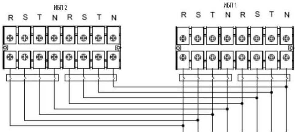
BbIXoBxOa
PnHmnaBbHa 3eKtpueckKa CXema npaannenbHoro noKnouehn (nmaOene S3M30KX, S3M40KX, S3M30KX/NIB uS3M40KX/NIB)
3.YctahOBka nHaCTpoiKa
PnHnnnnahbaa 3neKtpueckaa cxema npalannbno noKnKouenna (nna moedenn S3M60KX n S3M80KX)
3.6 NpokkoueHne BHeuHnx 6aTapei
16M0eN S3M30KX/NIB S3M40KX/NIB OchaiaOTcH HaeKHO BHYtpHeH CHTeOeA KkyMyIaTOpbHX 6Taape. Jn moe N S3M60KX S3M80KX TpeyOTcB HeHne 6OKn AKKMyIaTOpbHX 6Taape. Jn npoJIeHN BpeMeHN ABToHOMHO pa60TbS3M30KX u S3M40KX MOrYt HcNoB3OBaTBcB HBeHN E6IOKN AKKMyIaTOpbHX 6Taape. Hapdy c npoJHEm BpeMeHN ABToHOMHO pa60Tb, IpKnIOUeHNE DoONHITebbIX BHeHxN 6Taape npBBeTe K yBENHNO BpeMeHN 3apJkN.
Ha npmbednHn HnKne nnnnoe noa3HO Meonnoxe Hae p3bema nno knoe HBeue He batae K TOM (Moohctbo 30 / 40kBA), K KOtOPOy noKnIOaETcB BHeun 6nok AkkymnyTopbix 6atape 7. Ha nnoctpaun BN3y noka3ana cxema noKnIOeHna dner moen mooHoctb6n80 KBa. CnyeIte yka3AHm No yCTahOBKe 6noka aKKymnytoptbix 6atape, nnoxennbM B erp ykoBDCTbe nob3oBaTeJyEeNTecB ToM, YTO Ka6ennn noNHOCTbBOCTABNEHb CBON pa3bEmbl. Pn noKnIOeHHm 6atape BO3MOKHO He3NaHTebHO HCKpeHne. 3To ABNEHne CHTaTcH HopMaNBbIM.
He noKIOuayIe H He oTKIOUaIe 6IOKn AKKyMnyAToPbIx 6aTapeB IO BpeMa p60b I5B peXmme nITAHMO t6aTape.
*He 60eep Tpex BheuHmX 6nOKOB AKKyMnyTOpHbX 6TaapeH na KaKmbl N5I.
Pa3bemdIpynIOKJIIOUeHINBHeUNHO 60kaAkkyMnyTApOBx6aTepei (JIA MOJ. S3M30KX/NIB N S3M40KX/NIB)
Пдкючиме Всшнхбатари КИБП мд. S3M30KX/NIB И S3M40KX/NIB
Пдкючени Вьшонхбатари KMЛМOD. S3M60KX S3M80KX
4. Nopradk əkcnnyatauinn
4.1PpHnDcTbN KHOKdncn
| Коньк Куншоньhoe Наразаиме | |
| Коньк ON/Enter ("ВКЛ/Bвор") | Б клочени NBП: Дд BA KИчουени NBП нажмite Ha 3у TKY KнОКУ и уderжавaite ee He MeHee 0,5 c.Коньka Enter ("ВВоД"): нажмite Ha 3у TKY KнОКU дд NOДТВЕРЖIDENHЯ BыбраHHо IОПIM B MEHNo HAcTpoE.K. |
| Коньka OFF/ESC ("ВыКЛ/OTmeHa") | Быкочени NBП: Дд BA KИчουени NBП нажмite Ha 3у TKY KнОКU и уderжавaite ee He MeHee 0,5 c.Коньka Esc ("OTmeha"): нажмite Ha 3у TKY KнОКU dд BOЗВрATA Bnpedbyduyim pa3dien MeHNo HAcTpoE.K. |
| Коньka Test/Up ("Tecr/Bbepx") | Тс electropованes 6batapen: Дд ТС electropованes 6batapen B peximax OH- naH N Freq. Converter* (ПЕОБР. YACTOTbl) нажмite Ha 3у TKY KнОКUи уderжавaite ee He MeHee 0,5 c.Коньka UP ("Bbepx"): нажмite Ha 3у KнОКU dд OTБРAPKEN CHIQUOSEI OINIM B MeHNo HAcTpoE.K. |
| Коньka Mute/Down ("OTknIOченie 3Byka / BnH3") | Отлочени 3BykoBoi сгналзазain: Дд отлочени 3BykoBOro сгнana нажмite Ha 3у TKY KнОКUи уderжавaite ee He MeHee 0,5 c.Падрбна Инфорmaцia п徳ставлеси в раздени 4.4.9.Коньka Down ("ВнДз"): нажмite Ha 3у TKY KнОКU dд OTБРAPKENп徳ыduyeim onpimin B MeHNo HAcTpoE.K. |
| Коньк Test/Up + Mute/Down ("Tecr/Bbepx + OTknIOчenie 3Byka / BnH3") | Дд BA xOda/BbIXoDA b/ɪz MEHNo Naжмite Ha 3у TKY KнОКU onDHBpeMeHNo NH Uderжавaite IX He MeHee 1 cekyndi. Падрбна Инфорmaцia п徳стavenи в раздени 4.7 МeHNo Setup (Hauahlha yctanobka) |
*PexHMM Freq. Converter ("Pipeo6p, cactoTbI) 03Haaet noctOaHHoe BixxoHoe HapnpaKHeH NocToHHy BixoHDHy cactOtY.
4.2 CBeToaNoDhIe HnHkAToPbI nXK-naHeIb
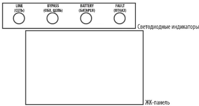
CBeToDnOHDhIE HNIMKaTOpbl:
Ha nepeDnei naHenn yctpoHCTBa pacnnonaIaoTc4 CBeToNIOHbIx HnIDnKaTopa, oTo6paKaioux npaoee coToHHe IVI:
| Mode / LED (Рек imm / CINД) LINE (ФETb) BYPASS (OBX. ZEПb) BATTERY (БATAPER) FAULT (OTKA3) | |||
| Initialization (Ин心智лесаць) ···· | |||
| Рек imm ождамия 0 0 0 | |||
| Рек imm рабъю обховно центо - 0 0 | |||
| Рек imm on-лайн - 0 0 0 | |||
| Рек imm пitaлия OT сатарей 0 0 - 0 | |||
| Рек imm Freq. Converter (П reproр. чASTOTы) | - 0 0 0 | ||
| Тechирovoltaicne сатарей | ···o | ||
| Рек imm ECO (эконOMICь) | ···o 0 | ||
| Отka3 | 0 0 0· | ||
PnmeaHne. 03naeT ropuim CND, a 03naaet BbKIOueHHB CND.
4.Порадokэкплyaтauи
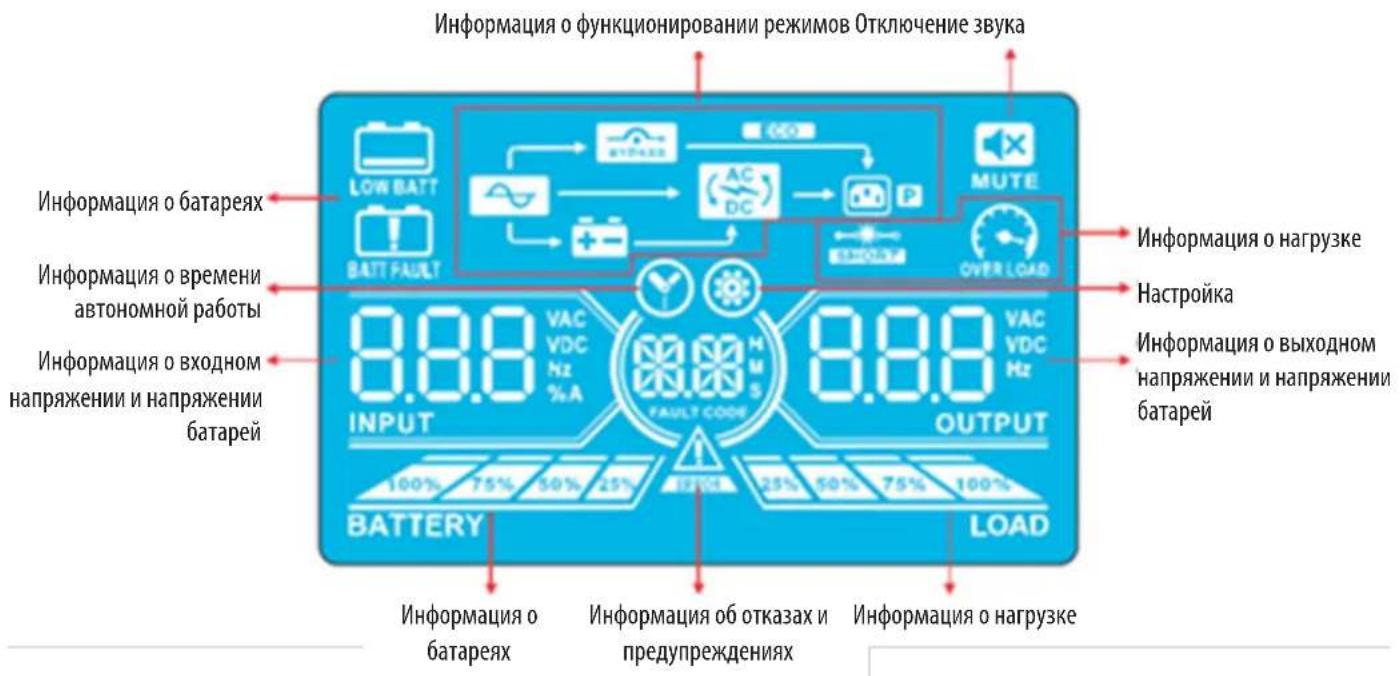
KK-nanenb
| Индikацьф Ункцьл. | |
| Инфомацьо o Вретени autohomer no pabotbl | |
| Показываet вретм, оставшеся do pastrади батер (цфразни) H: часl, M: минут bl, S: секунды | |
| Инфомацьо ob otka3ax i npedunpeckdienax | |
| Могалочи знayok cooblaeTo o prenympekdenu, a helpepbivho ropeians 3nauchok — ob otka3e. | |
| Еспз 3nauchok Fault/Warning (OTka3/Пrelypждени) Tropit helpepbivho, sm. onicahme kodob osh6ok B pa3dene 4.9.Еспз 3tot 3nauchok Miraet, sm. onicahne kodob prenympekdenu B pa3dene 4.11. | |
| Одknючени звук | |
| Показываet, чTo abarHЯня сгнанлзauaria N5P otkniocheHa. | |
| Инфомацьо o ВьхODHom habржени n habржени batapei | |
| Оторазает bvyodnoe habржени/чacToTu ilu n habржени 6batapen. VAC: bvoDnoe habprjxeHne, VDC: habprjxeHne 6batapen, Hz: chactota BxodHoro toka | |
| Инфомацьо o harpy3ke | |
| Показываet уrovesb harpy3knВ виde nHTepBaNoB 0-25%, 26-50%, 51-75% m 76-100%. | |
| Указываet на neperpy3ky. | |
| Укazываet на корOTkoe 3ambykane B harpy3ke ilu n Ha bixode. | |
| Инфомацьо o phyKuzioHnpobavani n pekmOB | |
| Показываet, чTo NBП подklуен K nctouHnky cTeBOrO pItaHni. | |
| Указываet на pa60Tu b pekmime pItaHni on 6batapen. | |
| Укazываet на pa60Tu no obxodnoi ceHni. | |
| Eco | Укazываet на To, чTo BKluyen pekm ECO (ФКOHOMUHbI). |
| AC DC | Укazываet на pa60Tu no ceHni npeobpaZobatela. |
| P | Укazываet на habluyne pItaHni ha bixode. |
4.Порадokэкплyaтauи
4.3BykoBaaCnHaHn3aun
4.7 MeHIO Setup (Haayabha yTaHOBka)
IyBxa/ByxOa B/3 MeHIO Setup (HaaybHa yTaHOBKa) OHOBpeMeHHo HAKMITE Ha KHONKTI Test/Up (Tect/Bbepx) Mute/Down (OTKn.3Byka/Bn3) MyepKMBAIte Hx He MeHee 1 CekyHbl.
JaHACrpoKmN6nONb3yOToTcPtnnapaMeTa.Cm.npeCTabIeHHbHnHexpehcyHok.
PapMeTp 1 cyjKtI dy yctaHOBKn BaepnHObTnporpamM. YcTaHOBOUHbe IpOporpAmMb npdCTaBHeB B pNMBeEHbIX HnHex TaBmuax.
Iapametp 2 Iipametp 3 npedctablaot coob onuun uun 3nauehena hactpoek nkaqdo nporpaMMb.
Icnnne otKnoaetcaepe3 10 MmHyt noCte BbInonHeHH noCneHrero deTbH. DnHnA cyHKnBkIOueHa Ha NOCTOHH OCHBE.
PnmeHne. HmMeHnnporpaMm nnapaMeTPOB noB3yHeCb KHOKnKaMn "Up/BePx"nn Down/BnH."
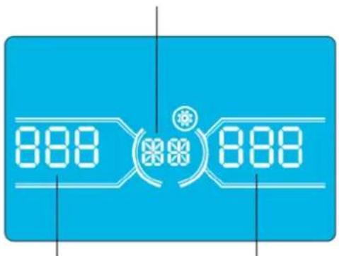
Napamertp 1
Napametp 2 Napametp 3
4.Порадokэкплyaтauи
Ipeueheh nporpamM,doctynnbixnna Napametpa 1:
| КoД OnicanHe | Рек imm рабови пообхони цп / 6e3 bixodnoro habржени | Рек imm пeremenhoTo kaka | Рек imm ECO (экономчный) | Pekim CVCF | Pekim paobt ot 6atapei | Technobahne 6atapei |
| 01 Bixodnepe habржени DA* | ||||||
| 02Частota BixodnoTo TOKA DA | ||||||
| 03Дмалдзн habржени ддя обхони цп DA | ||||||
| 04Дмалдзн частот ддя обхони цп DA | ||||||
| 05ВлочипспспспспспспспспспспспспспспспспспспспспспспспспспспспспспспспспспспспспспспспспспспспспспспспспспспcDA | ||||||
| 06Дмалдзн habржени ддя рек imm ECO (экономчный) DA | ||||||
| 07Дмалдзн частот ддя рек imm ECO (экономчный) DA | ||||||
| 08 Habрочиka peжима паobы по обхони цп DA | ||||||
| 09Уstановka мадсально ддяпьостни ра措дкпбатаре DA | DA | DA | DA | DA | DA | DA |
| 10Заразерворано 3apeзерворано по ддя ддяпинецфунци в буduшем | ||||||
| 11 Habрочиka Фунци "topaero" pezerba DA | ||||||
| 12Овиратье пoteу сны сны DA | DA | DA | DA | DA | DA | DA |
| 13Каллбравka habржени δатаре DA | DA | DA | DA | DA | DA | DA |
| 14Pergunlrbovka habржени заюногу усторства DA | DA | DA | DA | DA | DA | DA |
| 15Pergunlrbovka habржени пеобразовета A | DA | DA | DA | |||
| 16Pergunlrbovka habржени пеobразовета B | DA | DA | DA | |||
| 17Pergunlrbovka habржени пеobразовета C | DA | DA | DA | |||
| 18Каллбравka habржени на вьхode A | DA | DA | DA | |||
| 19Каллбравka habржени на вьхode B | DA | DA | DA | |||
| 20Каллбравka habржени на вьхode C | DA | DA | DA | |||
| 21 Habрочиka зараздногу тoka DA | ||||||
| 22 Habрочиka каллесъв заюньх плат DA | ||||||
*DA O3haaet, 4to taKaan nporpamMa MoKet 6bIb yCTAHOBHeHa B daHHoM peKHe.
PnmeHne. Bce Hactpno npapametpo coxpaHOTcT oToNo cne 0aTHoO tKIOueHHN bHnHaHm NoNDKIOueHHN BHTpeHHe HnBHeHsB aTaepn. 7rAHOe OKIOueHHNE WbI O3Haayet nepeBOD BXoHOrO BkIOuATEB NOXKeHMe OFF (BbIK) B pexMpepaBo no 6xOHOu CEH/63 BbIXoHOrO HAnpRKeHHN.
01: BbIXoJHoe HaprrKeHne
02:Yactota BbIXoHOrTo k
HntepcHactpoika
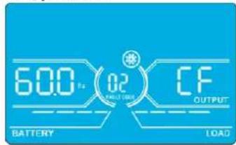
60Tü,peXMMCVCF
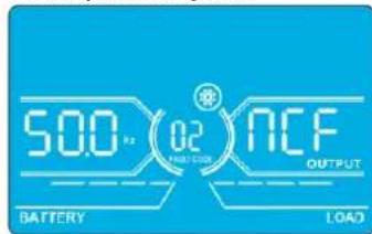
50T,HopMaIbHbIpeKIM
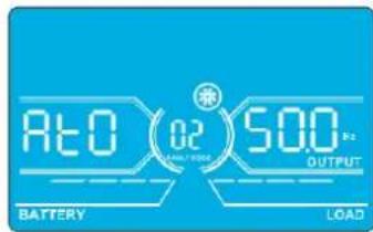
ATO
Napametp2:chaTotaBbIXoHoroToKa
YCTAHOBKa YACTOTbI BbIXoHOrO ToKa.ДЯ YCTAHOBKn Iapametpa 2 Moryt 6bITb bIbpaHbI CneyIoUme TpN onuM:
50.0 Hz: Hactpoika qacctobb BbIXoHOrO ToKa 50,0 Tl.
60.0 Hz: HAcTpoKa qAChToBbBixOaHOrO ToKa 60,0 T
ATO: npBb6pe daHHoOnuHm qactota BbXoHoro ToKa yCTaHabnBaetcB COOTBETCBM C NocEnHM 3aHKnCPOBAHbIM 3aHennm npbMbHHeHoo Yactotb. EOnn OHO coCTabnEeT 46do54T,TO qACTota BbXoHoro ToKa yCTaHabnBaetcPabH0y 50,0 T. ECnOHOcoCTabnEeT 56do54T,TO qACTota BbXoHoro ToKa yCTaHabnBaetcPabH0y 60,0T. Onn ATO yCTaHOBneHa no yMOJuaHHIO.
Napametp 3: yactothbien pexHM
YCTAHOBKa YACToTb BbIXoHOrO ToKa B Pexnme CVCF Nn H E B pexnme CVCF. IyctaHOBKn Iapametpa 3 Moryt 6bItb Bbl6paHbI CneDyUoune DBe OUIuN:
CF:YctahOBKa IBP BpeKIM CVCF.PnBb6ope DaHHo ONuIN Cactota BbxOHO TOKa 6yETaФmKpObaHa HypoHe 50TINN60 Tc cornaCHOHCTPOKe Iapametpa2. Hactota BXoHOrTO KaMOket HaxoHTBCB Dnana3OHe OT46do64Tc.
NCF: yCTaHOBKa IbIb HopMaIbHbIpeKHM (HepeKMMCVCF).PnBbIbOpoe DaHHoIOnuIcTota BbIXOHOrTOKa CHXPOH3MpyETCAchToToBxOHOrTO KaBuaana3OHe 46~54 THa yPoBHe 50 THa Buaana3OHe 56~64 THa yPoBHe 60 TCo rCaHcHO HAcTpoKePiapAmTePa2. PnBbIbOpoe 50 TCa KauCTBePiapamTa2 IbIb NpeXoDHT BpeKm paobTo b6atae BcNyUae BbxOda cactToBbXoHOrTO KA3 aPpeBbI duAna3OHa 46~54 T.PnBbIbOpoe 60 TBa KauCTBePiapamTa2 IBIpeXoDHT BpeKm paobTo b6atae BcUYaee BbxOda cactToBbXoHOrTO KA3 aPpeBbI duAna3OHa 56~64 T.
*EcnB KaueCTBe NapaMetpa 2yctahOBHeNO ATO,To Iapametp 36ydt Oto6paKaTaTeKyuio yactOTy.
15: PeryunpoBkA HanpJxKeHnI ppeo6pa3ObaTeTnA
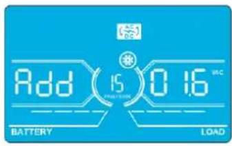
HntepcHactpoika
Napamr2: Bb6paBfHKuHAdd (Pn6aBntb) HIN Sub (Y6aBntb) IIN KoppeKtpoBKN HAnpJKeHH Npe06pa3oBaTeJI A.*
Napamtp3:ДмаланOH HanpxkeHm coctabnE rO 09,9B npn 3aueHm no ymoJauHIO B.
*BenHnHa npaMeTpA Add (Pn6abntb) nIb Sub (Y6abntb) cooTBeTCTBye YcTaHOBneHHOMy BbxOJHOmy HapJxKeHHIO.
16: PerynpoBka HanpJxKeHn ppeo6pa3oBaTeNa B
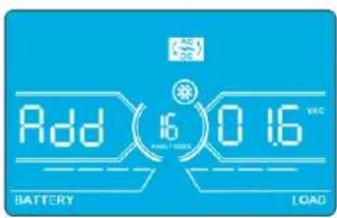
InTepeicNaTpoika
Napamtp 2: Bb6paBf yHKuHnAdd (Pn6aBntb) nnn Sub (Y6aBn) nna KoppeKtnpOKn HnnpJKeHHn Npeo6pa30BaTeIe B*.
Napamtp3:Imana3oH HanpXeHH coCTaBnE rTO 0 Do 9,9 B npn 3HaueHH no yMoJUaHHO B.
*nnpndabneHHBeneHHbHnpanpaeHHNpeo6pa3obatenaB 8 dyet otobpaKahtcno 1 noJ adnnncbo Rdd mnn SUB.
17: PerynpoBka HanpJxKeHn pneo6pa3oBaTeNa C
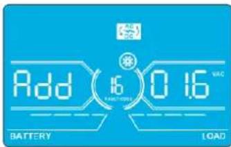
HntepcHacptponka
Napamtp 2:Bb6paTb yHKunu Add (Pn6aBntb) mN Sub (Y6aBntb) nKoppeKtnpOBKn HnpanJKeHnna pno6pa3oBaTeNa C*.
Napamtp3:MaanaohHnpanxekhencoctabnreT O 9,9B npn3haeynno ymoanuAHO B.
*DnpeTcAsBeHHBnHapRaeHHe npeOpa3oBaTeaC 6yDenOtOpaKaTaCnNo 2 noN aHaNNb0 Rddnn SUB.
18:KannibpoBka HanpIeHnHa BbIXoJe A
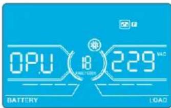
Интурфий С��pondа
Napametp 2: Bcerda oTo6paKaet OP.V B KaueCTBe BixOJHO To HnpanKeHn.
Napamert 3: OTo6paKaet pe3yIbTaB HHTpeHHeRo N3MepeHHeHa HApXeHHeHa BbXoA De A. OH MoKet 6bIt bOkan6pObaHnyTeMa HauTn KhoKN Up/Bepx MIn Down/Bn3 B COOTBcTBm Cpe3yIbTaOM N3MepeHHe, NOUYeHbIM C BHeHrO BoNTMtpa. Pe3yIbTa KaIIb6PbKn BBOJITCBA DECTBHe HAcTaHem KhoKN Enter (BBoI). KaIIb6pOboHbIM dAna3OH OrpaHnBaTc npedanm +/-9B.3a fHKnna 06bHNO nONb3yETd nCttem CnapaJIbNbHM nOdkIOueHEm.
19:KannibpoBbKa HanpJxKeHnHa BbIXoJe B
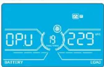
HntepcHactpoika
Napametp 2: Bcerda OTo6paKaet OP.V B KaueCTBe BixOJHOro HAnpRaeHnna
Napamr3:0t6paKaet pe3yIbTaB HHTpeHHeRo N3MepeHnHa npAkeHn Ha BbXoBe B. OH MOKe 6bIt OTaKl6pObaH nyTeMa HaaTm KONKU Up/Bepx HIn Down/Bn3 B COOTBETCTBN C pe3yIbTaOM N3MepeHn, NOJYeHbIM C BHeHrero BOnBTMetpa. Pe3yIbTa KaHbPbKn BBOuTcBA DeCTBne HauKaTHM KONKn Enter (BBo). KaHbPOBuHb ImaNa3OH OrpaHmHBaTeC npEpenaM +/-9 B. 3ta fHKua O6bHNo nONb3yeTc Dn CNTcEM C npaJIeNbHbIM nOdknOueHem.
*Ia npdctabnHbBmUHb HnnpJekHb Ha bXdoe B 6 dyet orobpaKaTbCry cNo 1 noHaNtncbO CP.U.
4.Порадokэкплyaтauи
20:Kann6pobka HanpaXeHna BaixOde C
InTepfeic NaTpoika
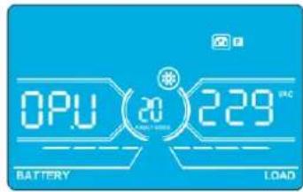
Napametp 2: Bcerda OTo6paKaet OP.V B KaueCTBe BixOHO HAnpAKeHn.
Napamr3:0To6paKaet pe3yIbTa BHTpeHHeRo h3MepeHnHaPaeHnHa BbXoCe C. OH MoKet 6BtB OTaKnI6pOah NyTeMa HaaTm KhoNkU Up/Bepx Nn Down/Bn3 B COOTBcTBnC Pe3yIbTaOM h3peHn, nOlyeHbIM C BHeHro BObnMetpa. Pe3yIbTa KaIIb6pOKn BBOJITCA BJeCTBnE HaxaTMem KhoNKn Enter (BBoD). KaIIb6pOboHb nnAna3OH OrpaHnmbaETc npedann +/-9 B. 3Ta fynKzua 06byNo nclnb3yETd nCttem c npalnnenbHbIM nokknueHem.
*Ia npEcdTaNHe BmHbHb HnpanKeHnHa BbXohe C6yder otobpaKaTaBc NnCNo 2 noHaadnnhcbO P.U.
21:HaCtpoIka3aPraHOroToKa
InTepeic Hactpoika
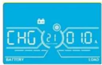
Napametp 2:CHGyka3bIbaeTHa yHKUIO KOppeKTHPOBKN3aApHOrTo KA.
Napamr3:YCTaHbMaBcT3pAHybToK.ⅡIana3OH DaHHo HAcTpOKn:OT 1do4A.3HaueHne no ymoHauHIO:2A dna MoJeNe MOHOCTbHO 30K/40K 4A dna MoJeNe MOHOCTbHO 60K/80K.
30K-40K: KoppeKtpyET 3apAHyb TOK TOBko DnO yDHOH 3apAHyo PnATbI, yCTAHOBHeHHO HA N6Pi. B cIyuae yctahOBKn 6Oonee OHOH 3apAHyo PnATbI daHHa FyHKuHa He paBoTaT.
60K-80K: KoppeKTpyet 3apnHmTOK TOnbKO dna DByx 3apnHbix nnat, yctahOBneHHbx Ha IVBn. B cnyae yctahOBKn 6Oone Dbyx 3apnHbix nnat daHHa FyHKun He pa6oTaET.
PpmeHne. Nocne yBnHnHn HnCnA 3apnHbNnTnBceYCaTHOBnHnHe 3apnHbNt nIaTb3apnKaOT 6aTapeOc MaKHMnblHOuMOIOCTBO, coBETCTByoue ToKy 4 A. PnpndarotaCBA TmN KOMnNEKTOB paucnepnHn3apnHbNx nIaT: dna HbIMoDene S3M30KX n S3M40K (KOMnNEKT Tnna CBKIT30-40) n dna HbIMoDene S3M60Kx n S3M80K (KOMnNEKT Tnna CBKIT30-80).
22:YcTaHOBkaKoJIuYeCTBa3aPAnHbIXnIaT
5. CpeiCTBa B3aHMoJeICTBnA
5.1 Pa3bem Дд noKIOHcHn HHTeJIeKToIbHbIX cpeCTB KOHTpOJa: SNMP-KoHTpOJa cHcNoIb3ObaHHeM KapTbI WEBCARDLX mN ynpabHeHne nocpeCTbOM "cyHX" KOHTaKTob C nCnoIb3ObaHHeM KapTbI RELAYCARDSV (onuHOHaIbHbIe KapTbI)
YCTAHOBNTB 3OT pa3bem onIIOHAnbHyu KapTy WEBCARDLX dI INCTaHIOHOrO ynpabHeHn I5II KHOHTPOJIa 3a eTO cOCToHHeM Yepe3 cTeB. 3T0 pa3bem TAKKe MOKeT McIOJIb3OBAbCJ
dIy YCTAHOBKn KapTb RELAYCARDSV B cENAX o6ecneueHn BO3MOxHOCTn B3aIMoJeCTBn C nCNOb3OBAHnEM cyHX X KOtAKToB. Boee npdoHa HΦOpMaunr pndctabHeBa
pykoBOcTBax nonb3oBaTeRn KapT WEBCARDLX RELAYCARDSV Ha caIte
www.triplite.com.
PnmuueHne. OdnoBpeMeHHo MoKet HcNlo3bOaTbCra TOnkO OHa KaPa.
5.2 Pa3bEm EPO
Pa3bEm EPO BxOynt B 6a30ByK KOMIIeKaTauH DnI o6ecneueHn 6e3oNaChTOh 6bEka. IIO yMOJIaHIO OH HopMaIbHO 3AMKHyT (H.3.): npH 3aMKHyTBIX KOHTaKTx 1 n 2 IVIpa6oTaET B HOpMaIbHom pexHMe. JnI 3aIeCTBOBaHn FyHKuH N EPO pa30MKNHTe KOHTaKtB 1 n 2.
5.3 Flopt RS-232
Iopr RS-232 BCTPOeH 3aHIO naHEnb IBP (B moEgX S3M30KX u S3M40KX) nnn yctaHOBne 3a nepeHn DBepei (B moEgX S3M60KX u S3M80KX) dna o6ecneHn BO3MOxHOCTN 06cnyBaHHy yCtpoCTBa npn 6OBHeHHn Bepu nporpaMMHoro 06ceueHHn IBI.
5.4 NopT USB
3T0TnpTnpednHa3NaueHToBkoDnCnyKe6bHxZeEi.
Mogenn S3M30KX n S3M40KX
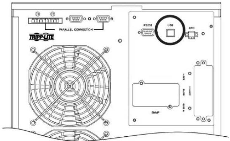
Moei S3M60KX u S3M80KX
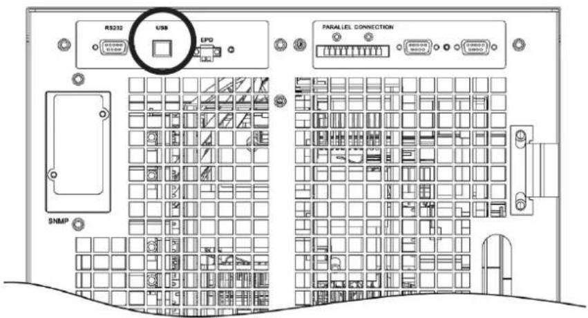
6. BbIaBHeHne uYcTpaHHeHHe HncnPaBHOCTe
Bcnyae HapuHHeHH HOpMaHbHO pa60bI IV5Pi YctAHOBITE Bo3NHKUyIO npO6JIeMy CnCIOJIb3OBAHMe yKa3aHm, pIpuBeJeHHbIX BnpEcdTabHeHHmHXe Ta6nIe.
| Симптом Возмочьая р Primа Соста устеняп. | ||
| Осуства Иndицamma и сгнанов на поедима панени дады писnomральс neteвom злелковотnam. | Helenburghoe лима Нетджхоюпordкючени nctochnika bxdnofo pintanma nepemehnoro toka. | Уб dedиь в наджхости рordкючени вхodно кабеля к сети питань. |
| На XX-Dи检п cease мигаot Занок и сдддддддддддддддддддддддддддддддддддддддддддддддддддддддддддддддддддддддддддддддддддддддддддддддддддд徳. | Сразыдане Фунckшь варийно оtmлочени питань (EPO).В заюмент bухлочаь EPO haxodttcB costони "OFF" ("ВыКЛ") пбо размнкуту перемьчka. | Замкичь сөөь дэг оtmлочени phунckшь EPO. |
| На XX-Dи检п cease мигаot Занок и Excekyнддддддддддддддддддддддддддддддддддддддддддддддддддддддддддддддддддддддддддддддддддддддддддддддддддд�. | Helenburghoe рordкючени bvetшь лима Buhtprenneь 6batapen. | Уб dedиь в падыности раджхости рordкючени bexex 6batapen. |
| На XX-Dи检п cease мигаot Занок и Excekyнддддддддддддддддддддддддддддддддддддддддддддддддддддддддддддддддддддддддддд徳. | Перетузka IVБ. Otmлочite Лшнixnotpebteilees ot bixdo | Да MSII. |
| Перетузka IVБ. Питанime ystpoictrB, рordкючених к IVБ, осыесьлaitca HeocspedtbeHHOTo 3elKTPuCHCKSOTENPEZDHyUZCEN. | Оtmлочь 히шихnotpebteilees OT bixdo YAISI. | |
| Равота IVБ по obxodniho сөгллзabokropobahа посе HeodokpahbIXx peperpyzOK. Питанime рordкючени bxtchpoCTBbXyTPOCTB OCSUeCTB ocuyecTBaHTAE TcHOCPEDCTBEHHOOTL3eKTPocetN. | Оtmлочite Лшнixnotpebteilees OT bixdo YAISI, 3atem Blyklnohtb IVIи 3anyctntb erO choba. | |
| ОвSpecааотся кOD Hencspabrooctri 43.На XX-naihenn BvICBeVHbAeTc 3auchok HEnpepbivbHb 3ByKBOB CunHAN. | Длitleьная перетузka и отka3 IVБ. Автomatческоe Otmлочени IVБ. | Оtmлочь пиншхixnotpebteilees OT bixdo YAISI andyctntb erO choba. |
| ОвSpecааотся кOD Hencspabrooctri 14, 15, 16, 17, 18 ил 19. Na XX-naihenn blybcueHbAeTc 3auchok HEnpepbivbHb 3ByKOB ComHAN. | Авторатческоe оtmлочени IVБИЗ-3a koperTKORO 3aMbKAnHBA B bixodnoi ceNi. | Проберъп, праиьнь лим рordкючени bbyxodnaя поровдаи и не hayхогТСЯ рordкючени b yctpoiCTBaВ coSTOnHNIM KOPOKTORO 3aMbKAnH. |
| На XX-Dи检п cease otobpaЖаOTc rduyime кoblb HEnpcpabHbTb 3ByKOB ComHAN. | Вутreneяная NeocnpabHcStb IVБ. 06patNTbca KdInepy. | |
| Вremя abToHOMHoi paobbyе He COOTBETCBYET homHaHbHomU 3auchenIO. | Helenhajar Zapadka 6batapei. 3apadmitb 6batapei B teuehe me Ka | Минимуm 7 часи роверьн IX emKoCTb.Еси побilema coхсан'tcra,образьгся Кдinepy. |
| Helenhajar Zapadka 6batapei. 6batapitbca KdInepy dlya 3aMeHb 6batapei. | ||
| На XX-Dи检п cease мигаOTЗачkn и Excekyндддддддддддддддддддддддддддддддддддддддддддддддддддддддддддддддддддддддддддддддддддддддддддддд徳. | Бл_OKровьkl mlim OTka BeHTMJIATORA lm60 cllshkom BvCoKaJ TempepaTypa IVB. | ПроберьтRobapotь вcertimTaytorob IVsbatapitbcs KdInepy. |
| На XX-Dи检п cease otobpaЖаOTc koid predyprjckdenia 02 I MIRaTe 3auchok ExcekyndINO noDAeTc 3ByKOB ComHAN. | Оточdnен�ь BXODHOro HeITrPahlborO npoboda. Прobervьт | Восстановьпordкючени BXODнoi HeITparl. ECSI yka3aHooe coedinchenme B nopadJa, Ho\ пожdnржdenie coxpanHeTcra, CM. pazden 4.7. Дя BXODa B MeHNo POBerPk Haniuchny Heitparl Chneuyet Chuaana pOBerPb,Чтбу napametr 3 bivoyet Hа "CHE". ECSI STO yCNOBe BvIpONHeNo, HaxaTb Ha KNOpKY "Enter"(ВвоD)".Посle того кач Занчok "CHE" zamirgaet, Сюва haxaTb Ha KNOpKY "Enter"(ВвоD)"Дя OTKIOUChENIA CunHana.В счuae coxpaneHnna PdeynpeDITeHBO CunHana pOBerPb coTcTOnHne BxodNbix pdeoxpahntenei L2иL3. |
| Выхod n3стray BXODHOro predyoxpahnteЯ L2ил L3. | Замень пredoxpahntel. |
7.XpaHHeHnTexHnueckoe 6cnyXnBaHne
7.1 XpaHeHne
IbI DOnJxepHbCB YCHCTOM N3aunuHemMeTe PnT TempeType MeeHe 40°C INOTHCINBHO BNAKHOCTM Mee He 90% (6e3 6pa3OBaHmN KOHNcHcATA). IIO BO3MOXHOCTx paHHTe IbI B erO 3aBOckoi TpAcnopthoy uynokBe. B Cnyae yctahOBkU IbI 6oJe eumpe3 6 MecueB nocne er o npuyehnpe3apdite 6atapein B teuehne kakminmym 24acob nepei Hauanom hncnbOAHn. He paccHTbBAHTe Ha To, tO npKnluohoe o6OpDyOBaHne 6ydet oecneHoo nTuHaem ot 6atapein IbI Do MoMeHTa ux noHno 3apdKn.
Pnme H. B cyuae haoxckdH N 5B BV bkyIIOeHNOM cOToHHN H pnoTaeHHN dInTeBHOro nepHOa BpeMeHN erO cneyET nepHOIMcckn BKIOUaTHb C eIb0 o6ceNEHn BO3MOKHO nDapA K 6atape WII DOnJKe H BkIOuHTBCr C ceJIbIO No3APADIK 6atape He MeHee Yem Ha 24 hca HnpePBHBNO paobtBu KaJdbie 3 Mecra. HeBbIOINHEne Tpe6oBAHN OTHOCTeBHIO nepHOINcckn NO3apAKN 6atape MoKet HaneCTH MM Heo6pATHMbl BpeI.
7.2 TexHnueckoe 06cnyKuBaHne
-Функшоюроваи He 65п CBa3аH O onaChbIMn DЯЖИЗн HapraжehnM. Ero peMoHT DoJIKeH IpoI3BODITbC TOnbKO KBaIIHfUHpOBaHHbIMN CneuaJIHCTAMN NO TeXHueckomy 6cbnyKWBAHIO.
JaXe nocJe OTKIOUeHnIbIOT 3NEKTPNuecko cetB BHTPN erO Kopnyca ocTaHO TOnEHNMaJIbHo OAnChbE KOMNoHeHtbl, NOJKNIOUeHHbIe K6IbOKaM aKKyMnaTOpHBx 6aTapei.
IpeBbInHHeM IIO6bIX pa60 NT texHMueckomy 0cNyKnBaHmIO U/IM pEmOHTy OTKnIOHTe 6aTapeu y6eDntecb B OTCytCTBm 3JIeKtpueckoro TOKa HOnaCHOro dJr KHN3Hn HapraKeHHa Ha BbIOdaX KOHeCaTOpOB BbcKOi eMKoCTn (HaNP. Bus-KOHdEHCATOpOB).
3aMeHa 6aTapeH N KOHTpObHbIe OnepaH MOrTy BblONIHbTaC TOnbKO KBaIhHcIUPoBaHbIMm TexHnueckHMn CneuaIaNCTaMn C nPiHrTHEm Heo6xOIMbIX MEP npeIOctOpOXHOCTH. BblonHeHne paobT noTexHnueckOMy o6clnyKbBaHIO 6aTapeNocTOPOHHMm HuaAMn HEoNYCAeTCA.
- PpeH naHOM pa60n ToxHueckomy 6OcnyKuBaHmIO HIN peMOHTy y6eHITecB OTCYCTBHN HApXeHMeMxDy KIeMMaMn 6atapen n 3emne. 3NeKtpueckra eHb 6atapen He 3oJIPOBaHa OT BxOHOrO HApXeHMe, MeKdy KIeMMaMn 6atapen n 3emne MOrT Bo3HkAtpb OnaChbIe IIN KU3HM HApXeHMe.
HeaJnEkauee obaaene Me 6batapeMIM MoKET nPmbcTn K npaaKeHIO eNkTpUeCKm TKOM m Bo3MHKBoHEnIO KOPOrTO 3MbKaHm. IpeepHaayamop pa60nt ToexHHueckomy 6cbnyBaHIO Hn peMOHTy Heo6xoHIMO ChrTB BCE hapYhBie HaCb, 6paCneTb, KOJIbua n Dpyrme MetaIIuWecKne ppeMeTb, a camu TaKne pa60tbn PON3BOJNTb C nOINb3OBAHmem TOnbKO INCHTPyMeHTOB C 130nIPOBaHbIMu pyKaAMn yPKoATKaMn.
- Pn3aMeHe 6aTapee Cneyet YcTaHabMbBaTb 6aTapeu TORO JKe TINa, ToJ Ke EMKoCTN B TOM JKe KONMueCTBe.
HnB KOem Cnyae He yTHIN3Npyte 6bapen nyTe CKIN4AHNA.3To MOKET npMBCTN K B3pbIBy 6bapee. YTHIN3aMIO 6bapee cneyET npOn3BOIMTB HaJIeXaMM Opa3OM B COOTBECTBNM C MeCTbIMH HopMaTHBbIMM Tpe60BaHMAAM.
He BcKpbBaiTe 6aTapeH He pa3pyuAte HX KOHCTpykUIO. BbIeKaOUsm I3 HIX 3JIeKToPIM MOKeT ABLrTaC TOKChYbIM I bIb3iBaTb NopaeHne KooN cIN3nCTOn OboONoOH rna3.
Bo 36eJahnE OaHcOCTN Bo3rOpAHn3aMeHnTe BbIeUdUne H3 CToPnpeOxpaHnTeIN ToBko Ha aHaIIOH TOrO Xe THNa IHOmIHnHa.
- He pa36mpaie Te 16P1.
7.3 BaTapea
Bnctouhikax becepe6oHoro nHTAHN TrippLite cepin S3MX nCIOb3yOTc repeMtuHbe CBNUOBO-KNCOTHbe akkymIaTOpHBe 6aTape. Cpok cnjKb6bl 6bAtpen 3abmnt ot ee pa6oeyemtnepatpyb, nInTeJIbHOCTn IcNOb3OBaHn u cactObl 3apJKn/pa3paJKn. Ppi paoBe B yCNOBHX bBcOKHX temepatypu cactOn 3apJKe/pa3paJKe cpo KnyKb6bl 6bAtpen 6bIcTPOcoKpaauetca. Ina oecneueHH HOPmaHbHO rpoKa cny6b 6bAtpen npndepxHBAITe6 cndyoUnx peKOMeHa:
1.Подеркьаитepa6oук TeMнретурВДиANA3OHe Odo 40°C.
2. ONTMaHbHOe COOTHOJHe NpOw3BOIDHTeBHOCTn 6aTApEN H cPOKA ee CNYKbI DOCTHraeTcN pN peryuHpyeMoH TemnepeType 25^
3. Pn He6xmoCTX XpaHHe Hb TteHHe DInTeBHO npepnoa BpeMeHn CJeYeT NoHocTbIO nepe3apKaaTb 6aTape KacKbIe TpN Meca, a BpeM 3apJKn B KaKdOM TaKOM cnUyae DoJHKo CoCtABJIaTb He MeHee 24 yaocB.
7.4 BéNTnIaTOp
Pp pa6oBte B cyb0nax nobblhenbIX tempepatyp cpoK cyxkb6BeHTmIaTOPOB cokpaauetc.Bo BPema pa6oTb I5Pi CneyepertnpOuMeckn npOBepaH, HopmaIbHO JIn fyHKUOnHpyOT BCE BeHTmIaTOpI, y6exDaTcB CBO6OdHIOUIPKyIaUM Bo3Dyxa BOKpyr I5Pi BHyTprr Hero. B clyueae o6hApJxehna KaHX-n6o np6bEm Heo6XoDMo pOn3BcTeM 3aMeHy BeHTmIaTOPOB.
Pnme.3a 60oe npo6no Hnfoopmaue o npaepe npoebeHn texmneckoro 6cnymbna HpaataeB Cnykby texnueckon noepkkm KOMnHn Tripp Lte. He npom3bodnte texmneckoe 6cnymbnane camoctoTbelno npn OTCyTBn Hndnkae KBAHnKcaum.
8. TexHnueckne xapaKTepeNtIKN
Pa3Mepb6atapeHoro shka
12B65/100A·x40wT.
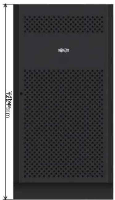
12B40A·u×40wT.
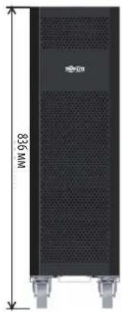
12B9/10A·x80wT.
| Модаlemбатерийньхшкфов | Быклочаел b komплесke | Габарuthье размeperы (B x Φ x Ω) мmОписиche | |
| BP480V100 | 400 A, 3-плочь | 1501 x 826 x 1136 | Батерийный škaф c 40 батергмx 100 A-ч |
| BP480V100-NIB | Батерийный škaф 6ez bataр, по расочаннь ha установу 40 bataрx 100 A-ч (c кабелядя падлочени bataри и вьклочателм) | ||
| BP480V65 | 300 A, 3-плочь | Батерийный škaф c 40 bataргмx 65 A-ч | |
| BP480V65-NIB | Батерийный škaф 6ez bataр, по расочаннь ha установу 40 bataрx 65 A-ч (c Кабелядя падлочени bataри и вьклочателм) | ||
| BP480V40 | 200 A, 3-плочь 1221 x 826 x 900 | 26 x 900 | Батерийный škaф c 40 bataргмx 40 A-ч |
| BP480V40-NIB | Батерийный škaф 6ez bataр, по расочаннь ha установу 40 bataрx 40 A-ч (c Кабелядя падлочени bataри и вьклочателм) | ||
| BP480V10 | Батерийх c 9 A-ч Празdoхсан'tel'ь (100 A) 836 x 250 x 779 | x 250 x 779 | Батерийный škaф c 80 bataргмx 10 A-ч |
| BP480V09Батерийньшkaф c 80 b ВPS480V10-NIB | |||
| Батерийный škaф 6ez bataр, по расочаннь ha установу 80 bataрx 10/9 A-ч (с Кабелядя падлочени bataри и празdoхсан'tel'm) |
1111 W. 35th Street, Chicago, IL 60609 USA - www.triplite.com/support
Bedienungsanleitung
Modelle: S3M30KX, S3M30KX-NIB, S3M40KX, S3M40KX-NIB, S3M60KX, S3M80KX
Eingang: 220/230/240 V (Ph-N), 380/400/415 V (Ph-Ph), 30 4 Drahte + PE

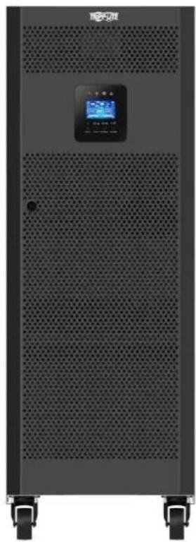


1111 W. 35th Street, Chicago, IL 60609 USA • www.triplite.com/support
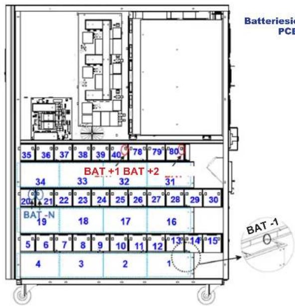
Linke Site S3M30KX/S3M40KX
3.5 USV-Parallelinstallation

WARNHINWEIS:

Manufacturing Excellence