
SU6000RT4UHVPM - Inverter Tripp Lite - Free user manual and instructions
Find the device manual for free SU6000RT4UHVPM Tripp Lite in PDF.
| Product Type | Online Double Conversion UPS |
| Brand | Tripp Lite |
| Model | SU6000RT4UHVPM |
| Rated Power | 6 kVA / 4.2 kW (power factor 0.7) |
| Input Voltage | 200-240 V AC single-phase |
| Configurable Output Voltage | 200, 208, 220, 230 or 240 V AC |
| Input/Output Frequency | 50/60 Hz (auto-detection or adjustable) |
| Conversion Technology | Online double conversion with zero transfer time |
| Battery Type | Sealed lead-acid batteries, hot-swappable |
| Display | Backlit LCD display 16x2 characters |
| Communication Interfaces | RS-232, USB, accessory slot for SNMP/Web card |
| Emergency Power Off (EPO) | Yes, via dedicated port |
| Maintenance Bypass | Yes, manual switch on removable PDU |
| Form Factor and Mounting | 4U rackmount, 4-post rail mounting (2-post kit optional) |
| Output Receptacles | NEMA L6-30R, L6-20R depending on PDU model |
| Integrated Protection | Input and output circuit breakers, EMI/RFI filter |
| Operating Temperature | 0°C to 40°C (32°F to 104°F) |
| Warranty | 2 years (batteries: 1 year outside U.S. and Canada) |
| Maintenance | No user-serviceable parts, battery replacement by authorized technician |
| Available Spare Parts | Replacement batteries (RBC), SNMP/Web cards, 2-post mounting kit |
Frequently Asked Questions - SU6000RT4UHVPM Tripp Lite
User questions about SU6000RT4UHVPM Tripp Lite
0 question about this device. Answer the ones you know or ask your own.
Ask a new question about this device
Download the instructions for your Inverter in PDF format for free! Find your manual SU6000RT4UHVPM - Tripp Lite and take your electronic device back in hand. On this page are published all the documents necessary for the use of your device. SU6000RT4UHVPM by Tripp Lite.
USER MANUAL SU6000RT4UHVPM Tripp Lite
Intelligent True On-Line UPS Systems
- Includes UPS system with internal battery system (5&6kVA), detachable PDU and detachable parallel PDU modules (6kVA)
Not suitable for mobile applications.
Important Safety Warnings 2
Mounting
Features
Connection
Optional Connection 12
Manual Bypass Operation 14
Operation 15
Internal Battery Replacement 28
Storage and Service 29
Warranty and Product Registration 29
Español
Français
Русский 88
PROTECT YOUR INVESTMENT!
Register your product for quicker service and ultimate peace of mind.
You could also win an ISOBAR6ULTRA surge protector—a \$100 value!
www.tripplite.com/warranty


Important Safety Warnings

SAVE THESE INSTRUCTIONS. This manual contains important instructions and warnings that should be followed during the installation and maintenance of this product. Failure to heed these warnings may affect your warranty.
UPS Location Warnings
• Install your UPS in a structurally sound area. Your UPS is extremely heavy; take care when moving and lifting the unit.
- Only operate your UPS at indoor temperatures between 32°F and 104°F (between 0°C and 40°C ). For best results, keep indoor temperatures between 62°F and 84°F (between 17°C and 29°C ).
- Leave adequate space around all sides of the UPS for proper ventilation.
- Do not install the UPS near magnetic storage media, as this may result in data corruption.
- Do not mount unit with its front or rear panel facing down (at any angle). Mounting in this manner will seriously inhibit the unit's internal cooling, eventually causing product damage not covered under warranty.
UPS Connection Warnings
- Isolate the UPS before working on this circuit.
- The power supply for this unit must be single-phase rated in accordance with the equipment nameplate. It also must be suitably grounded.
Equipment Connection Warnings
- Use of this equipment in life support applications where failure of this equipment can reasonably be expected to cause the failure of the life support equipment or to significantly affect its safety or effectiveness is not recommended. Do not use this equipment in the presence of a flammable anesthetic mixture with air, oxygen or nitrous oxide.
- Connect your UPS power module's grounding terminal to a grounding electrode conductor.
- The UPS is connected to a DC energy source (battery). The output terminals may be live even when the UPS is not connected to an AC supply.
Maintenance Warnings
- Your UPS power module and battery module(s) do not require routine maintenance. Do not open them for any reason. There are no user-serviceable parts inside.
Battery Warnings
- Connect only Tripp Lite battery modules (of the correct type and voltage) to your UPS power module's external battery connector.
- Batteries can present a risk of electrical shock and burn from high short-circuit current. Observe proper precautions. Do not dispose of the batteries in a fire. Do not open the UPS or batteries. Do not short or bridge the battery terminals with any object. Unplug and turn off the UPS before performing battery replacement. Use tools with insulated handles. There are no user-serviceable parts inside the UPS. Battery replacement should be performed only by authorized service personnel using the same number and type of batteries (Sealed Lead-Acid). The batteries are recyclable. Refer to your local codes for disposal requirements or visit www.tripplite.com/UPSbatteryrecycling for recycling information. Tripp Lite offers a complete line of UPS System Replacement Battery Cartridges (R.B.C.).Visit Tripp Lite on the Web at www.tripplite.com/support/battery/index.cfm to locate the specific replacement battery for your UPS.
- Fuses should be replaced only by factory authorized personnel. Blown fuses should be replaced only with fuses of the same number and type.
- Service and repair should be done only by trained personnel. Prior to any service work performed on hardwired power modules, they should be turned off or manually bypassed via the transformer. Prior to any service work performed on power modules that plug directly into wall outlets, they should be turned off and unplugged. Note that potentially lethal voltages exist within this unit as long as the battery supply is connected.
- Do not connect or disconnect battery module(s) while the UPS is operating from the battery supply or when the transformer module is not in bypass mode (if your UPS system includes a transformer module with a bypass switch).
- During "hot-swap" battery module replacement your UPS will be unable to provide battery backup in the event of a blackout.
- Only connect compatible battery module(s).
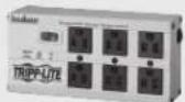
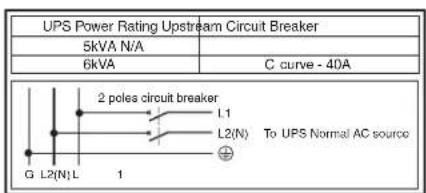
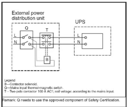
Required Protective Devices and Cable Cross-Sections
Recommended upstream protection
Mounting
Mount your equipment in either a 4-post or 2-post rack or rack enclosure. The user must determine the fitness of hardware and procedures before mounting. If hardware and procedures are not suitable for your application, contact the manufacturer of your rack or rack enclosure. The procedures described in this manual are for common rack and rack enclosure types and may not be appropriate for all applications.
4-Post Mounting
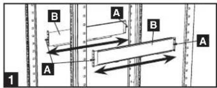
1 The included plastic pegs A will temporarily support the empty rackmount shelves B while you install the permanent mounting hardware. Insert a peg near the center of the front and rear bracket of each shelf as shown. (Each front bracket has 6 holes and each rear bracket has 3 holes.) The pegs will snap into place.
After installing the pegs, expand each shelf to match the depth of your rack rails. The pegs will fit through the square holes in the rack rails to support the shelves. Refer to the rack unit labels to confirm that the shelves are level in all directions. Note: The support ledge of each shelf must face inward.
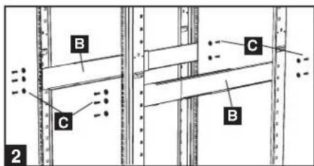
2 Secure the shelves B to the mounting rails permanently using the included screws and cup washers C as shown.
- For 4U equipment mounting, place 6 screws total at the front and 4 screws total at the back.
Tighten all screws before proceeding.
Warning: Do not attempt to install your equipment until you have inserted and tightened the required screws. The plastic pegs will not support the weight of your equipment.
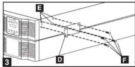
3 Attach mounting ears D to the front mounting holes of your equipment E using the screws provided F. The ears should face forward.
Note: It is recommended that you remove the internal batteries of the UPS prior to installation. This will remove excess weight and will allow safer handling of equipment. See Internal Battery Replacement section for battery removal instructions.
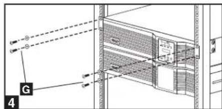
4 Using an assistant, lift your equipment and slide it onto the mounting shelves. Attach your equipment to the rack by passing the screws, nuts and washers (user-provided) G through its mounting ears and into the rack rails. Be sure to use separate rack rails for each individual component.
12kVA UPS Configuration—SU12KRT4UHW Only (Using 2 6kVA Power Modules)
See manual included with parallel PDU for SU12KRT4UHW Mounting.
2-Post Mounting (Optional)
To mount your 5kVA or 6kVA UPS in a 2-post rack, you must purchase a Tripp Lite 2-Post Rackmount Installation Kit (model: 2POSTRMKITHD, sold separately) for each power module and battery pack installed. See the Installation Kit's owner's manual for complete mounting instructions.
Note: 2-post mounting is not recommended for 12kVA UPS systems.
Features
Before installing and operating your UPS, familiarize yourself with the location and function of the features of each component.
Power Module Front Panel Controls
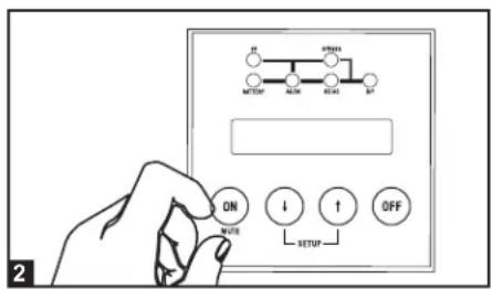
1 LCD DISPLAY: This backlit (16 × 2 character) dot matrix display indicates a wide range of UPS operating conditions and diagnostic data. It also displays UPS settings and options when the UPS is in setup mode.
2 ON/MUTE BUTTON: Press this button and hold it until you hear a beep to turn the UPS system's inverter ON. If the UPS's battery alarm is sounding, press this button to silence it.
3 SCROLL DOWN/EXIT SETUP BUTTON: This button allows you to browse through different options and power readings on the LCD display. Momentarily pressing it causes the LCD screen to display a different power reading (see "Operation" section). Pressing it and the SCROLL UP button together puts the UPS in setup mode, where this button is used to scroll through setup options and to exit setup mode.
4 SCROLL UP/SELECT BUTTON: This button allows you to browse through different options and power readings on the LCD display. Momentarily pressing it causes the LCD screen to display a different power reading (see "Operation" Section). Pressing it and the SCROLL DOWN button together puts the UPS in setup mode, where this button is used to select setup options.
5 OFF BUTTON: Press this button until you hear a beep to turn the UPS system's inverter OFF.
6 O/P (OUTPUT) LED: This green light will illuminate to indicate your UPS is supplying AC power to connected equipment.
7 DC/AC (INVERTER) LED: This green light will illuminate to indicate the UPS's DC/AC inverter is activated.
8 BYPASS LED: This yellow light will flash when the UPS is providing filtered mains power without engaging the converter or inverter. If this LED is flashing, connected equipment will not receive battery power in the event of a blackout. If Economy Mode is enabled, this LED will be on solid and the connected equipment will receive power in the event of a blackout.
9 AC/DC (Converter) LED: This green light will illuminate to indicate the UPS's AC/DC converter is charging the connected battery pack(s).
10 BATTERY LED: This green light will illuminate when the UPS is discharging the battery to provide connected equipment with AC power. An alarm will sound which can be silenced by pressing the ON/MUTE button. This LED will remain lit after the alarm is silenced.
11 I/P (INPUT) LED: This green light will illuminate to indicate an AC input supply is present.
![graph TD A["UP"] --> B["BATTERY"] B --> C["AC/DC"] C --> D["BYPRESS"] D --> E["DC/AC"] E --> F["O/P"] G["SETUP"] --> H["ON MUTE"] I["SETUP"] --> J["↓"] K["SETUP"] --> L["↑"] M["SETUP"] --> N["OFF"]](/content/2026/04/647283/images/1f3e8db02cd02cc47f3439618af2df104b45897ff8fd2d0d5cf5bbf2cba9993c.jpg)
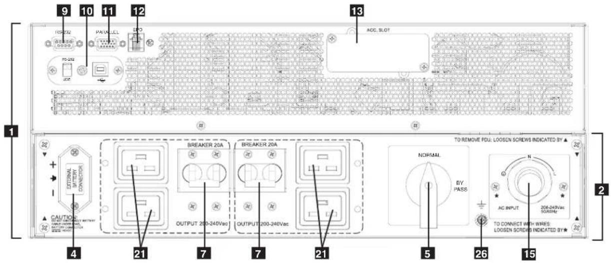
Features (Rear Panel) See "Features" section for feature descriptions
SU5000RT4UHV—5kVA UPS System
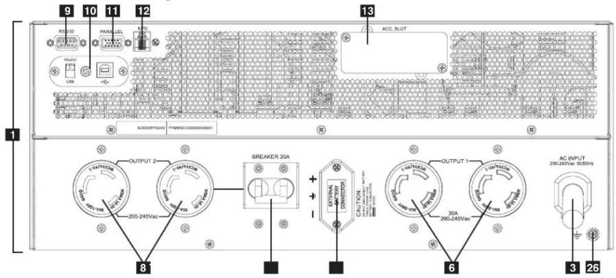
SU6000RT4UHV—6kVA UPS System with NEMA PDU
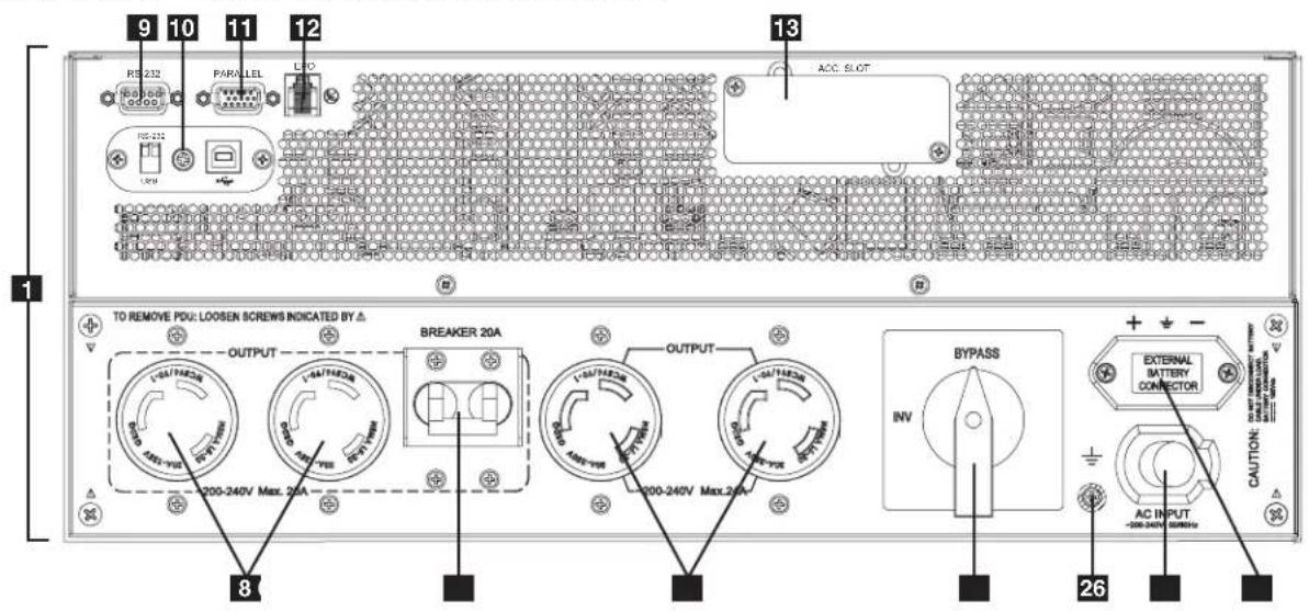
SU6000RT4UHVHW—6kVA UPS System with Hardwire PDU
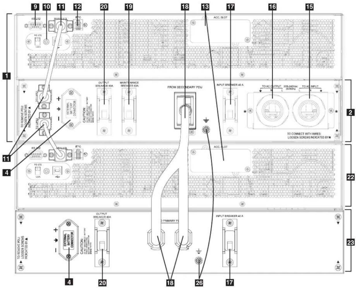
Features (Rear Panel) (continued) See "Features" section for feature descriptions
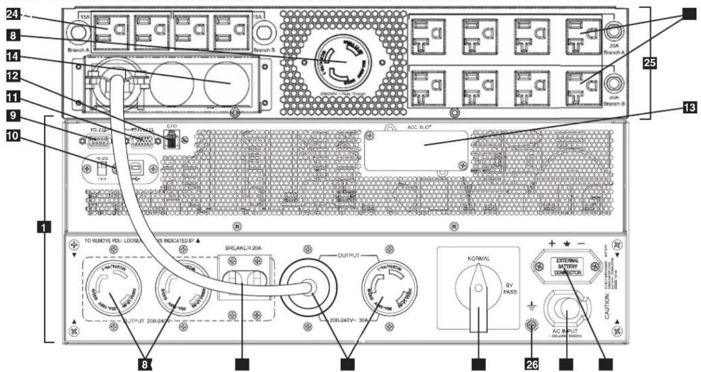
SU6000RT4UHVG—6kVA UPS System with IEC PDU
SU12KRT4UHW—12kVA UPS System and Parallel PDU Modules
Note: See the manual included with the Parallel PDU for 12kVA installation, configuration and setup instructions.
Features (Rear Panel) (continued) See "Features" section for feature descriptions
SU6000RT4UTFHW—6kVA UPS with Hardwire PDU and 6kVA Isolation Step Down Transformer (SU6000XFMR2U)
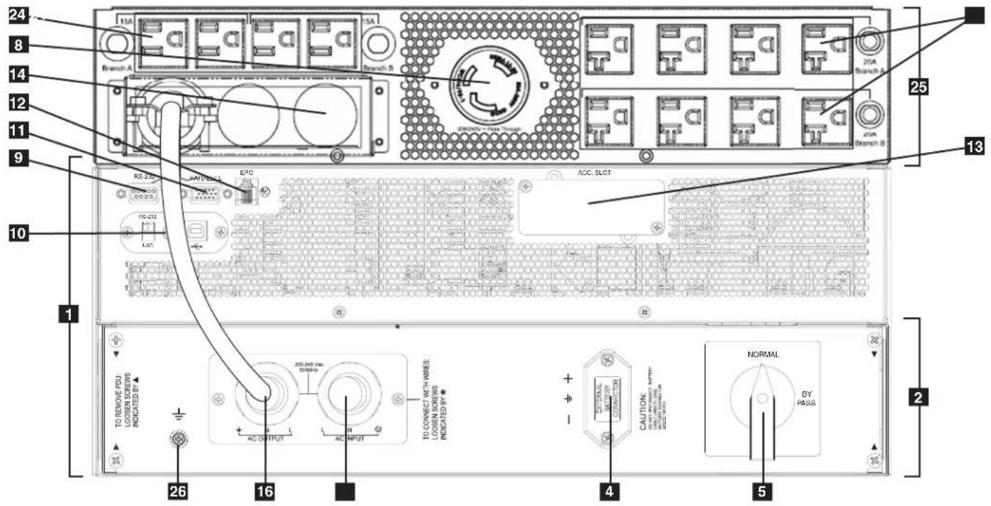
SU6000RT4UTF—6kVA UPS with NEMA PDU and 6KVA Isolation Transformer
Features (Rear Panel) (continued)
1 UPS System: This self-contained unit houses the UPS system's power and control components as well as its internal batteries.
2 Independent, Detachable Power Distribution Unit (PDU): This self-contained unit houses the UPS system's input and output components along with a bypass switch. When the switch is set to bypass the PDU can be completely removed from the power/battery module for routine power/battery maintenance without disrupting power to the connected loads. While this switch is set to bypass, connected equipment will receive unfiltered AC mains power, but the equipment will not receive battery power in the event of a blackout.
3 AC Input Cord: Connects directly to wall receptacle providing 200-240V AC utility power.
4 External Battery Connector: Use this to connect one or more Tripp Lite battery modules to the power module. Remove the cover for access. The power module will not start without a connection to a charged battery module. Refer to the battery module Owner's Manual for connection instructions and safety warnings.
5 Maintenance Bypass Switch: This switch allows qualified service personnel to remove the detachable PDU from the power/battery module for routine maintenance without disrupting power to connected loads. While this switch is set to BYPASS, connected equipment will receive filtered AC mains power, but the equipment will not receive battery power in the event of a blackout. See "Manual Bypass Operation" section for complete bypass procedure.
6 L6-30R AC Output Receptacles: Accept direct plug-in connection of NEMA L6-30 equipment plugs.
7 20A Output Breaker: One double-pole circuit breaker controls output power from the receptacles indicated on each model.
8 L6-20R AC Output Receptacles: Accept direct plug-in connection of NEMA L6-20 equipment plugs.
9 RS-232 Communication Port: This female DB9 serial port may be used to connect your UPS to a workstation or server. It uses RS-232 protocol to communicate with a connected computer. It is used with Tripp Lite software and the included serial cable to monitor and manage the UPS remotely over a network and to automatically save open files and shut down equipment during a blackout. See "Optional Connection" section for details.
10 Mini-Slot: USB connector (disabled by default—DIP switches in the RS-232 position; to enable, move both DIP switches to the USB position). An optional Contact-Closure card is available if needed (Tripp Lite part # RELAYIOMINI).
11 Parallel Connector: For UPS communication in parallel (functional only on the 6kVA model). Refer to the manual provided with the Parallel PDU Kit. For more information, visit www.tripplite.com/support.
12 EPO (Emergency Power Off) Port: The power module features an EPO port that may be used to connect the power module to a contact closure switch to enable emergency power off. See “Optional Connection” section for details.
13 Accessory Slot: Remove the small cover panel to install optional accessories to remotely control and monitor your UPS system. Visit Tripp Lite on the Web (www.triplite.com) to learn about available SNMP, network management and connectivity products that may be installed in this slot.
14 Transformer AC Input/Output Terminal Block (6kVA UPS only): Use this terminal for interfacing an approved PDU system.
15 Utility Input Terminal Block (6kVA UPS and 12kVA IEC/PARALLEL/HARDWIRE module only): Use these terminals to connect your power module to utility power. Unscrew and remove the cover over the block for access.
16 Equipment Output Terminal Block (6kVA UPS and 12kVA IEC/PARALLEL/HARDWIRE module only): Use these terminals to connect your power module to your equipment. Unscrew and remove the cover over the block for access.
17 AC Input Breaker: One double-pole circuit breaker controls input power to the power module.
18 Parallel Power Interconnect: For use with secondary parallel PDU only.
19 Maintenance Breaker (12kVA UPS only): Controls maintenance to the UPS.
20 AC Output Breaker: One double-pole circuit breaker provides Bypass for the parallel system to the load.
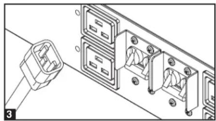
21 AC Output Receptacles (6kVA UPS/ IEC PDU Module only): Accept direct plug-in connection of IEC-320-C20 equipment plugs.
22 Secondary UPS Module
23 Secondary PDU Module
24 5-15/20R AC Output Receptacles: Accept direct plug-in connection of NEMA 5-15P or 5-20P equipment plugs.
25 Isolation Step Down Transformer: This self-contained unit provides a means to connect both low-voltage and high-voltage devices to the UPS system.
26 Ground Screw: Use this to connect any equipment that requires a chassis ground.
Connection
Note: The output voltage is set at 208\~(default) by the manufacturer. If you need to change the output voltage of the UPS, refer to "Output Voltage Selection" in the "Operation" section. You should select the correct output voltage before connecting your equipment to the UPS.
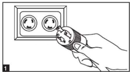
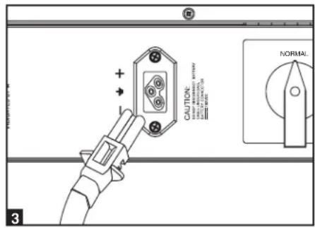
1 Plug your UPS's input cord into an electrical outlet. (SU5000RT4UHV, SU5000RT4UTF, SU6000RT4UHV, SU6000RT4UTF)
Your UPS must be connected to a dedicated circuit of sufficient amperage.
Note! After you connect the UPS to a live AC power source, the UPS LCD will display "BYPASS MODE" and will automatically charge its batteries while providing power to the output.
If you have a PDU with manual bypass, set the PDU bypass switch to "NORMAL."
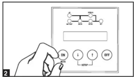
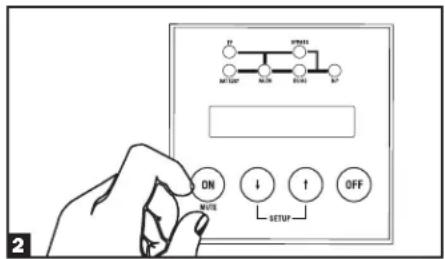
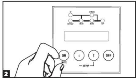
2 Turn UPS ON.
Press the UPS's "ON" Button until you hear a beep to begin inverter operation. Your UPS will perform a brief self-test and show the results on the LCD Display. See "Startup Self-Test" in the "Operation" section for the display sequence. Your UPS will now provide filtered power to the AC output.
Note: UPS system will function properly upon initial startup; however, maximum runtime for the unit's battery will only be accessible after it has been charged for 24 hours.
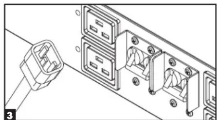
3 Plug your equipment into your UPS.
Your UPS is designed to support electronic equipment only. You will overload your UPS if the total VA rating for all the equipment you connect exceeds the UPS's output capacity. Do not connect household appliances or laser printers to the UPS's outlets. To find your equipment's VA ratings, look on their nameplates. If the equipment is listed in amps, multiply the number of amps by the input voltage(200V\~240V) to determine VA. (Example: 1 amp x 208V = 208VA).
4 Turn UPS OFF (Optional).
Press the UPS's "OFF" button until you hear a beep. You will be presented with a Yes/No option. Select Yes to continue to turn off the UPS. Select No to cancel. The UPS will continue to automatically charge its batteries and provide unfiltered (BYPASSED) AC output as long as AC input power is present. To completely deactivate the UPS, unplug the UPS's input cord when the UPS system is in standby mode.
5 UPS Cold Start (Optional).
To use your UPS as a stand-alone power source when AC input power is unavailable (i.e. during a blackout), you can “cold start” your UPS and power connected equipment from the UPS’s battery. Your UPS’s battery must be at least partially charged for this operation to succeed. Press and hold the “ON” button until you hear a beep to cold start your UPS. The LCD Display will show ON BATTERY MODE. Battery power will begin discharging. Some electronic equipment may draw more amps during startup; when cold starting, consider reducing the initial load on the UPS.
Terminal Strip Input Connections
(SU6000RT4UHVHW, SU6000RT4UHVG, SU6000RT4UTFHW)
Note: For SU12KRT4UHW Hardwiring information, see the manual included with the Parallel PDU.
Hardwiring Cautions
- Wiring must be done by a qualified electrician.
- When making wiring connections, observe the cable connection regulations appropriate to your area [e.g. National Electrical Code (NEC) in the U.S.] at all times. Be sure to install an easily accessible disconnect switch in your installation wiring so you may cut off the UPS's AC input during fires and other emergencies. Ensure that cables are fitted with cable sleeves and are secured by connector clamps. Tighten connections with a torque of not less than 24-28 inch-pounds (2.7-3.2 NM).
• Make sure that your equipment is properly grounded. - Using cables of improper size may damage your equipment and cause fire hazards. Choose appropriate cabling and protection circuits to make wiring connections. Ground conductors must be the same size and type as the power conductors used.
• Refer to National Electrical Code (NEC) guidelines for proper wire gauge and output protection circuit requirements.
Connection (continued)
Terminal Strip Connection—IEC PDU Module (SU6000RT4UHVG)
| Model Input Voltage | Maximum Rated Input Current | Typical Wire Size | |
| SUPDMB6KIEC 200~240V (L-N) 30A 8 mm2 | |||
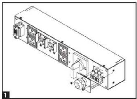
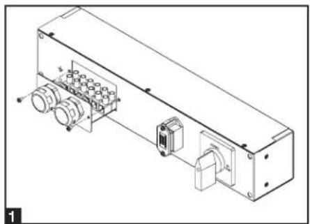
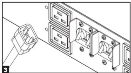
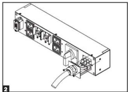
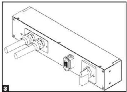
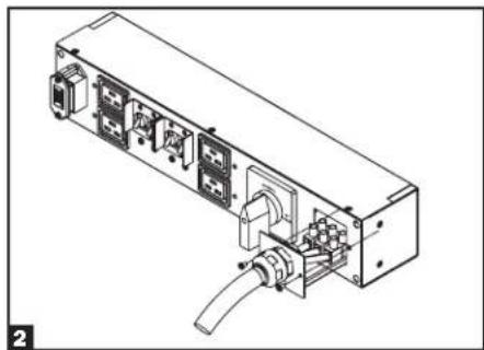
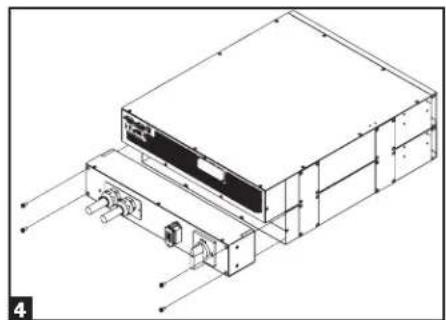
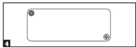
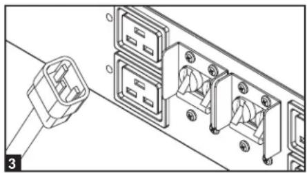
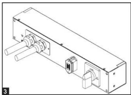
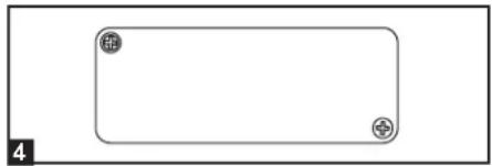
1 Unscrew 3 screws to remove the terminal strip cover and slide out as seen in diagram 1.
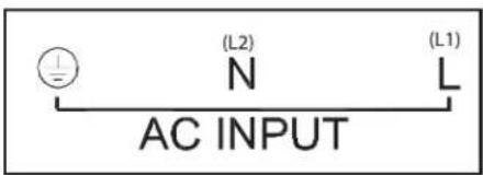
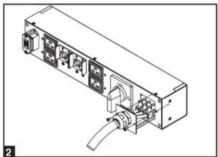
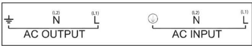
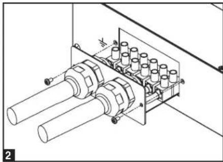
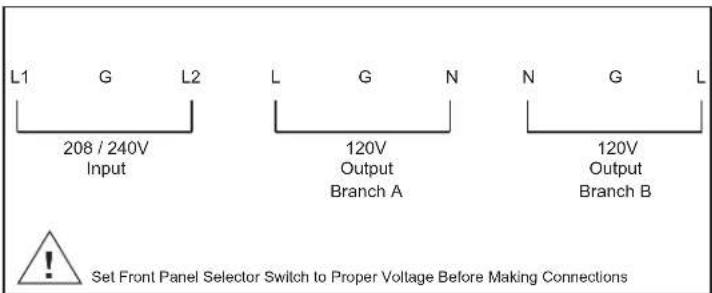
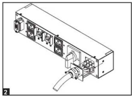
2 Connect the L1, L2 and Ground wires (Hardwire-In, Receptacle-Out) according to markings on the connectors as seen in diagram 2.
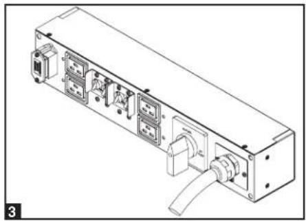
3 Slide in and reattach the terminal strip cover with the 3 screws from Step 1.
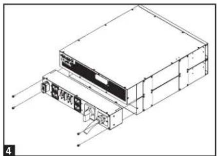
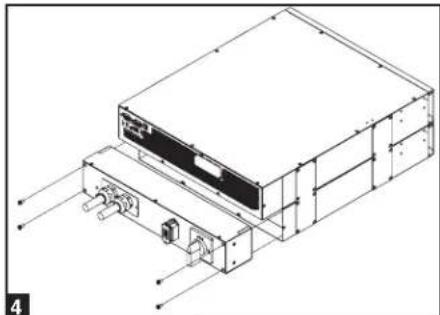
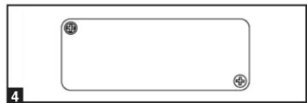
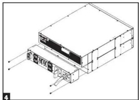
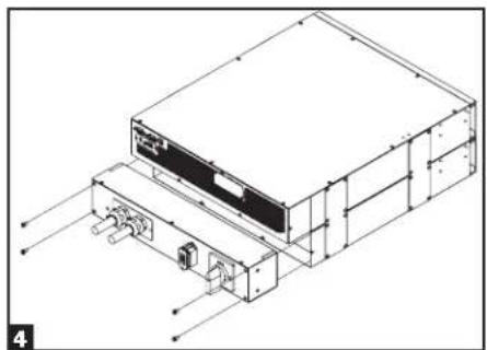
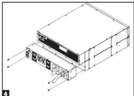
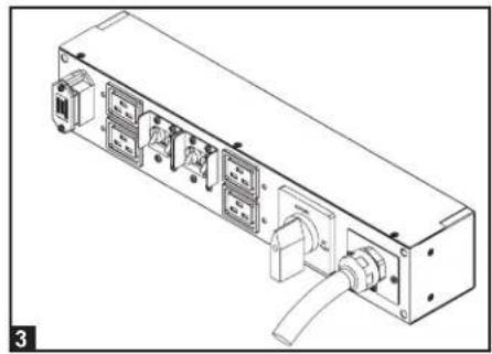
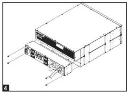
4 Attach the PDU to the UPS system using 4 screws as seen in diagram 4.
Terminal Strip Connection—Hardwire PDU Module (SU6000RT4UHVHW, SU6000RT4UTHFHW)
| Model Input Voltage | Maximum Rated Input Current | Maximum Rated Output Current | Typical Wire Size | |
| SUPDMB6KHW 200~240V (L-N) 32A 3 | DA 8 mm2 |
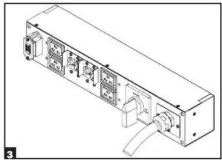
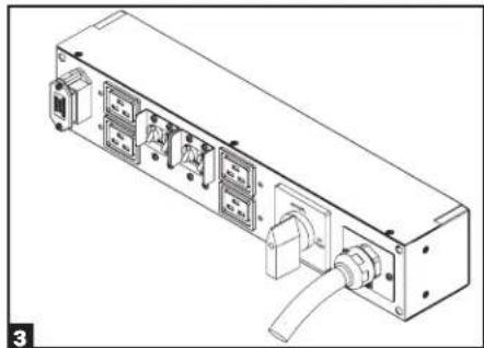
1 Unscrew 3 screws to remove the terminal strip cover and slide out as seen in diagram 1.
Connection (continued)
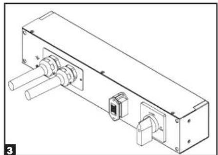
2 Connect the 2 sets of L1, L2 and Ground wires (1 Input, 1 Output) according to markings on the connectors as seen in diagram 2. Be sure to connect one set of wires to the input terminals and the other set to the output terminals.
3 Slide in and reattach the terminal strip cover with the 3 screws from Step 1.
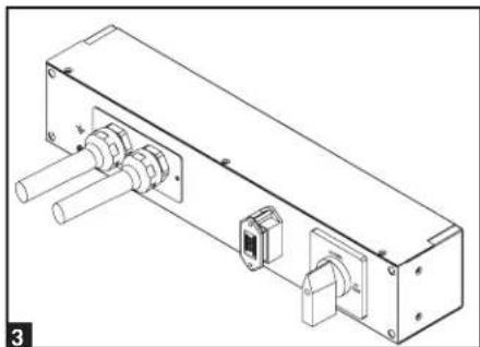
4 Attach the PDU to the UPS system using 4 screws as seen in diagram 4.
Hardwiring the Transformer Bundle (Input/Output)
SU6000RT4UTF
- Plug the XFMR into the UPS.
- Connect the transformer to the UPS. This can be a hardwire connection, outlet connection or both, provided the combined load does not exceed capacity.
SU12KRT4UHW
See manual included with Parallel PDU for connection, setup and installation information.
Optional Connection
The following connections are optional. Your UPS system will function properly without these connections.
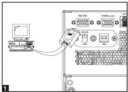
1 RS-232 Serial and USB Communication Connections
Use the included cable to connect the power module's "RS-232" port to the communication port on your computer. This will allow full network monitoring and control of your UPS system. Install on your computer the Tripp Lite PowerAlert software appropriate to your computer's operating system. The UPS is also equipped with a USB communication module.
An alternate contact closure module is available if necessary (Tripp Lite part # RELAYIOMINI). By default, this module is disabled. To enable, move both DIP switches to the USB position. Enabling this module disables the RS-232 port. The RS-232 port is also disabled with the installation of an optional SNMP/Web card (Tripp Lite part # SNMPWEBCARD). The SNMP/Web card can be used simultaneously with the USB communication module.
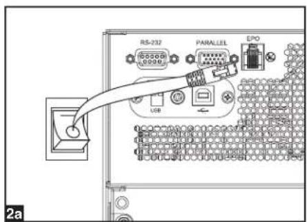
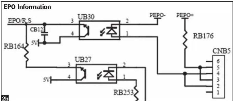
2 EPO Port Connection
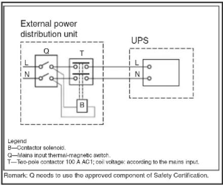
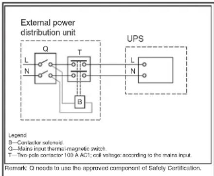
This optional feature is only for those applications that require connection to a facility's Emergency Power Off (EPO) circuit. When the UPS is connected to this circuit, it enables emergency shutdown of the UPS's inverter and inhibits transfer to internal bypass. Using the cable provided, connect the EPO port of your UPS (see 2a) to a user-supplied normally open switch according to the circuit diagram (see 2b).
EPO connector
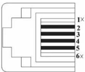
Pins 4 and 5 or pins 2 and 3 can be shorted to activate the EPO.
Note:
- If using a cable other than what is supplied, the cable should not exceed 350 feet or have a resistance of greater than 10 ohms.
- If a non-latching EPO switch is used, the EPO must be held for a minimum of 1 second. This does not apply to a latching EPO switch.
- For setup of a normally closed-switch EPO connection, please contact Tripp Lite Technical Support.
CAUTION: The EPO port is not a phone line surge suppressor; do not connect a phone line to this port.
Optional Connection (continued)
UPS Unit State when asserting EPO with AC line present:
LEDs Output Fans Serial SNMP USB LCD Screen
OFF OFF OFF OFF OFF OFF "Emergency Stop"
To restart the UPS unit after asserting EPO with AC line present:
- Verify that the EPO assertion has been removed or cleared.
- Remove AC line power to the UPS unit.
- Reapply AC line power. Now the UPS will start back up in Bypass mode and the LCD will display "BYPASS MODE".
UPS Unit State when asserting EPO without AC line power:
LEDs Output Fans Serial SNMP USB LCD Screen
OFF OFF OFF OFF OFF OFF "Emergency Stop"
To restart the UPS unit after asserting EPO without AC line power:
- Verify that the EPO assertion has been removed or cleared.
- Reapply AC line power to the UPS unit. Now the UPS will start back up in Bypass mode and the LCD will display "BYPASS MODE".
3 External Battery Connection
Your UPS comes with a robust internal battery system; external batteries are needed only to extend runtime. Adding external batteries will increase recharge time as well as runtime. The illustration shows the location of your UPS's External Battery Connector, where you will insert the battery pack cable. Complete installation instructions for your battery pack appear in the battery pack Owner's Manual. Make sure that cables are fully inserted into their connectors. Small sparks may result during battery connection; this is normal. Do not connect or disconnect battery packs when the UPS is running on battery power.
4 Accessory Slot
Remove the slot's cover to install an optional internal SNMP/Web accessory card (Model: SNMPWEBCARD) to enable remote UPS monitoring and control via SNMP, Web or telnet. (Tripp Lite's RELAYIOCARD is also available.) Visit www.triplite.com/support for more information, including a list of available SNMP, network management and connectivity products.
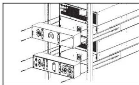
Hot-Swap Power Module Replacement*
WARNING! For qualified service personnel only. Failure to follow the bypass procedure completely will not adequately power down the UPS, resulting in the continued risk of death or injury from pontential contact with high voltage. The UPS and detachable PDU are extremely heavy. This procedure requires several people to perform.
The UPS system includes an independent, detachable PDU with a Bypass Switch. This switch allows qualified service personnel to remove the detachable PDU from the UPS for routine maintenance without disrupting power to connected loads. While this switch is set to "BYPASS", connected equipment will receive unfiltered AC mains power. But the equipment will not receive battery power in the event of a blackout.
* See manual included with SU12KRT4UHW Parallel PDU for Bypass.
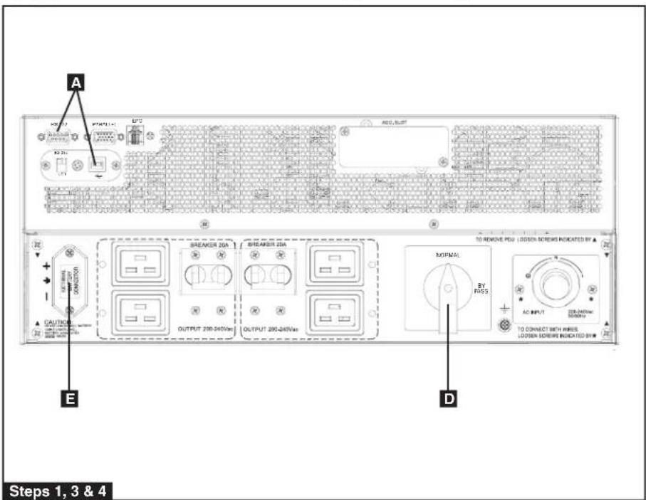
UPS Removal (6kVA Single UPS Power Module Configurations Only)
STEP 1. Disable PowerAlert and disconnect the SNMP or serial USB communication cables from the communication ports A on the UPS.
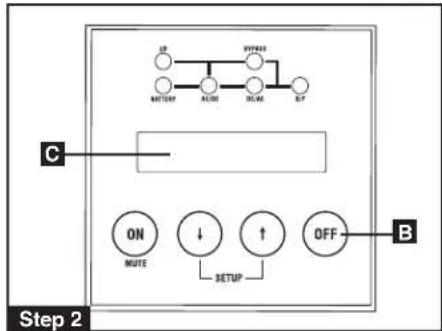
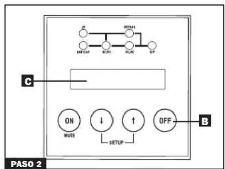
STEP 2. Press UPS's "OFF" button B, if the UPS is powered, until you hear a beep and see a "BYPASS MODE" message shown in its LCD Display C on the front of the power module. You will be prompted to enter "BYPASS MODE". Press UPS "OFF" button again to activate "BYPASS MODE".
STEP 3. Turn the detachable PDU's Bypass Switch D to "BYPASS" on the rear of the UPS PDU.
STEP 4. If an external battery module is connected to the UPS E, disconnect it from the UPS.
The UPS is now safely powered down and it can be detached from the PDU to perform maintenance/replacement.
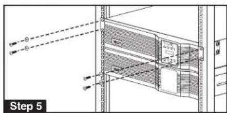
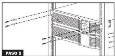
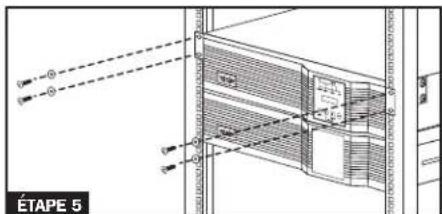
STEP 5. Remove the four screws that secure the front mounting ears of your UPS to the rack. With the PDU still attached, move the UPS system and PDU forward in the rack slightly (approximately 4 inches), being sure that both components remain adequately supported by the UPS's rackmount support rails.
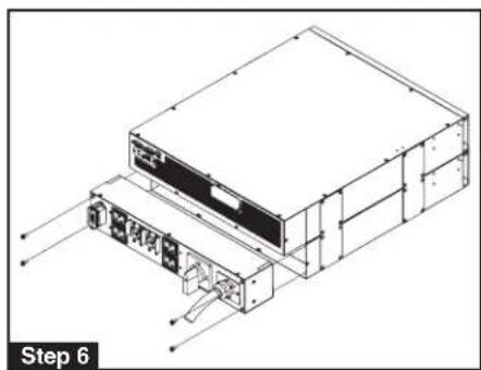
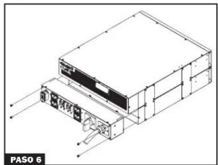
STEP 6. At the rear of the UPS, remove the four screws that hold the detachable PDU to the UPS that is being serviced. With an assistant holding the front of the UPS in place, carefully detach the PDU from the rear of the UPS and rest it on the UPS support rails. Remove the UPS power module from the front of the rack.

WARNING! High voltage! Risk of electrical shock!

Operation
LED Display Information
ONLINE Mode: AC input voltage in normal range: 156-280V.
![graph TD A["IPBYPASS"] --> B["Node"] C["AC/DCBATTERYDC/ACO/P"] --> D["Node"] B --> E["Node"] D --> F["Node"]](/content/2026/04/647283/images/160c953822c4e9ba129e6032ae8f05532d7d1273a3a4e97ad663dd0d26c2276d.jpg)
Battery Mode: When in Battery Mode, you will see the following LED display:
![graph TD A["IPBYPASS"] --> B["Node 1"] A --> C["Node 2"] A --> D["Node 3"] A --> E["Node 4"] A --> F["Node 5"] B --> G["AC/DCDC/ACBATTERYO/P"] C --> G D --> G E --> G F --> G](/content/2026/04/647283/images/40aa392608af55e9c9c41563c316cfbca9fb9f4a988af0d3015053ea1965b0c2.jpg)
EPO Shutdown (Frequency Conversion Mode): With an EPO shutdown with no output present, you will see the following LED sequence:
![graph TD A["IP"] --> B["Flashing"] B --> C["BYPASS"] C --> D["BATTERYDC/AQAC/DCO/P"] D --> E["Ground"]](/content/2026/04/647283/images/f2ae0b5943283ecda9a0bb32f6ebe9844c36e3465585010ccc3fd321be60a3e5.jpg)
Bypass Mode: AC input voltage in a range of: -20 to +15% of the rating voltage; Bypass Mode is enabled.
![graph TD A["IPBYPASS"] --> B["BATTERYDC/ACQDC"] B --> C["Flashing"] C --> D["Ground"]](/content/2026/04/647283/images/a87d52300a31d1565d4703d10f3dca64161e2f21094ddf1b6c61aa114c18748f.jpg)
AC Power Start Up: With an AC power start up, you will see the following LED sequence:
![graph TD A["IPBYPASS"] --> B["AC/DC/ACBATTERYO/P"] C["Flashing"] --> D["Central node"] D --> E["AC/DC/ACBATTERYO/P"] F["IPBYPASS"] --> G["AC/DC"] G --> H["DC/ACBATTERYO/P"] I["Flashing"] --> J["Central node"] J --> K["AC/DC/ACBATTERYO/P"]](/content/2026/04/647283/images/0af7c1670555ccdd64f995a9f2bd205d6359755a967dce1880189524b6814137.jpg)
EPO Shutdown (AC Mode): With an EPO shutdown having AC power present, you will see the following LED sequence:
![graph TD IP["IP"] --> A["AC/DC"] IP --> B["BYPASS"] B --> C["DC/AC"] B --> D["O/P"] B --> E["BATTERY"]](/content/2026/04/647283/images/33a4bac2e98459856acd05ed8d8e0955f1c9afd9677a0fb49e9e65207766e7aa.jpg)
Economy Mode: AC input voltage in a range between -10 and +10% of rating voltage; Economy Mode is enabled.
![graph TD A["IPBYPASS"] --> B["Node 1"] A --> C["Node 2"] A --> D["Node 3"] E["BATTERYDC/ACAC/DCO/P"] --> F["Node 4"] E --> G["Node 5"] E --> H["Node 6"]](/content/2026/04/647283/images/1a00b1bfa56c7804383a1393b257695f0d9341fba45369636361eeb5f7e9b202.jpg)
Cold Start: With a cold start, an On Battery Alarm will sound, and you will see the following LED sequence:
![graph TD A["IPBYPASS"] --> B["BATTERY"] B --> C["AC/DC/AC"] C --> D["O/P"] E["IPBYPASS"] --> F["BATTERY"] F --> G["AC/DC"] G --> H["DC/AC"] H --> I["O/P"] C --> J["↓"]](/content/2026/04/647283/images/1fc9bcf09b685f39d8551eb4a4a3d99480c65c1475599b3d890ca26c55e14a39.jpg)
Battery Independent Mode: In Battery Independent Mode, the same LED sequence as ONLINE Mode will display, but a "Bad Battery Alarm" will sound.
![graph TD A["IPBYPASS"] --> B["Node"] C["AC/DCBATTERYDC/ACO/P"] --> D["Node"] B --> E["Node"] D --> F["Node"]](/content/2026/04/647283/images/83b96bc59ec7bd8a25c855c2ce0ffdfbb72a7ce20a1a3f34ea4a21dfb9b118be.jpg)
Operation (continued)
Startup Self-Test
When you turn the UPS ON, it will enter Diagnostic Mode and perform a brief self-test lasting about 15 seconds. The results of the self-test are shown on the LCD screen in the sequence below.
![graph TD A["DIAGNOSTIC MODE FREQ OUT = 50Hz"] --> B["DIAGNOSTIC MODE INPUT 000V / 00Hz"] B --> C["DIAGNOSTIC MODE RECTIFIER OK"] C --> D["DIAGNOSTIC MODE CHARGER OK"] D --> E["DIAGNOSTIC MODE BATTERY OK"] E --> F["DIAGNOSTIC MODE DC BUS OK"] F --> G["DIAGNOSTIC MODE INVERTER TEST"] G --> H["DIAGNOST…](/content/2026/04/647283/images/6f50218c3cb9c93e0facc09a879d909dda2f6f982ffb75f5133ef8bffefe4425.jpg)
*Note: If the UPS is cold started, its BATTERY LED will be lit.
Failed Self-Test
If a problem is detected during the self-test, the LCD will display an error message. If your UPS displays any of the following messages in its LCD, visit www.triplite.com/support for service.
![graph TD A["BAD BATTERY!<br>CALL FOR SERVICE"] --> B["CHARGE BATT FAIL!<br>CALL FOR SERVICE"] B --> C["AC/DC FAILURE!<br>CALL FOR SERVICE"] C --> D["INVERTER FAILURE!<br>CALL FOR SERVICE"] D --> E["OUTPUT FAILURE!<br>CALL FOR SERVICE"] E --> F["FAN FAILURE!<br>CALL FOR SERVICE"]](/content/2026/04/647283/images/666f572589705fab26170c42d648c469b75cbcfee3f150bca4e2603c17d9ab35.jpg)
Operation (continued)
Normal Operation
During normal operation, the first line of your LCD Display shows which operating mode your UPS is in: Online Mode, Economy Mode, Frequency Conversion Mode, Battery Mode, Bypass Mode or Parallel Mode (12kVA model only).
Online Mode: The UPS provides AC power while utility power is available and switches to On Battery Mode instantly (zero transfer time) if AC power is interrupted.
Economy Mode: The UPS provides AC power at high efficiency while utility power is within +/- 10% rated AC input voltage and switches to On Battery Mode (8ms transfer time) if AC power is interrupted.
Frequency Conversion Mode: Used to convert your UPS's input frequency to a different output frequency (i.e. Input 60 Hz to Output 50 Hz. Note: Output will be turned off in Frequency Conversion Mode if the unit is put into Bypass).
Battery Mode: The UPS provides AC power from battery backup so long as battery power lasts. It switches back to Online or Economy Mode if utility power is available and shuts down if it runs out of battery power.
Bypass Mode: The UPS provides AC power while utility power is available. The UPS shuts down if AC power is interrupted.
Parallel Mode (SU12KRT4UHW model only): The UPS can provide redundancy up to 6kVA or power up to 12kVA. Refer to the manual provided with the Parallel PDU Kit for more information.
The second line of the LCD Display shows basic power conditions. In each operating mode you can push the SCROLL buttons to browse through these basic power conditions in the sequences shown below:
Display Information Online Mode:
| ONLINE MODE00.00KW / 000% |
| STANDALONE00.00KVA / 000% |
| INPUT VOLTAGE000V / 00.0Hz |
| BYPASS VOLTAGE000V / 00.0Hz |
| OUTPUT VOLTAGE000V / 00.0Hz |
| BATTERY CAPACITY000V / 000% |
| REMAINING TIME0000 MINUTES |
| ON-LINE 5/6KVAV00 CV01 |
Display Information Economy Mode:
| ECONOMY MODE00.00KW / 000% |
| STANDALONE00.00KVA / 000% |
| INPUT VOLTAGE000V / 00.0Hz |
| BYPASS VOLTAGE000V / 00.0Hz |
| OUTPUT VOLTAGE000V / 00.0Hz |
| BATTERY CAPACITY000V / 000% |
| REMAINING TIME0000 MINUTES |
| ON-LINE 5/6KVAV00 CV01 |
Display Information Frequency
| Conversion Mode: |
| FREQ CONV MODE00.00KW / 000% |
| STANDALONE00.00KVA / 000% |
| INPUT VOLTAGE000V / 00.0Hz |
| BYPASS VOLTAGE000V / 00.0Hz |
| OUTPUT VOLTAGE000V / 00.0Hz |
| BATTERY CAPACITY000V / 000% |
| REMAINING TIME0000 MINUTES |
| ON-LINE 5/6KVAV00 CV01 |
Display Information Battery Mode:
| BATTERY MODE00.00KW / 000% |
| STANDALONE00.00KVA / 000% |
| INPUT VOLTAGE000V / 00.0Hz |
| BYPASS VOLTAGE000V / 00.0Hz |
| OUTPUT VOLTAGE000V / 00.0Hz |
| BATTERY CAPACITY000V / 000% |
| REMAINING TIME0000 MINUTES |
| ON-LINE 5/6KVAV00 CV01 |
Display Information Bypass Mode:
| BYPASS MODE00.00KW / 000% |
| STANDALONE00.00KVA / 000% |
| INPUT VOLTAGE000V / 00.0Hz |
| BYPASS VOLTAGE000V / 00.0Hz |
| OUTPUT VOLTAGE000V / 00.0Hz |
| BATTERY CAPACITY000V / 000% |
| REMAINING TIME0000 MINUTES |
| ON-LINE 5/6KVAV00 CV01 |
Operation (continued)
Normal Operation
Display Information Parallel Mode (12kVA model only):
![graph TD A["PARALLEL MODE 00.00KW / 000%"] --> B["PARALLEL: MASTER 00.00KVA / 000%"] B --> C["INPUT VOLTAGE 000V / 00.0Hz"] C --> D["BYPASS VOLTAGE 000V / 00.0Hz"] D --> E["OUTPUT VOLTAGE 000V / 00.0Hz"] E --> F["BATTERY CAPACITY 000V / 000%"] F --> G["REMAINING TIME 0000 MINUTES"] G --> H["ON-LINE…](/content/2026/04/647283/images/ee873612ba42517bbd11c64766e1176651c694b0910729eb71d05a02b0904e5e.jpg)
NOTE: When two units are connected in parallel, the "Master UPS" will display "PARALLEL: MASTER" in this second screen. The display on the "Secondary UPS" will read "PARALLEL: SLAVE". If the two units are not paralleled successfully, both units will read "STANDALONE" in this second screen.
UPS Setup Menu
Press the UP↑ and DOWN↓ buttons simultaneously for 3 seconds until the SETUP MENU screen appears as seen below:

Press the UP↑ button to enter Set Up Mode.
To enter Set Up Mode, you will be required to enter a password.
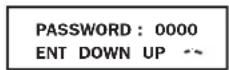
Numbers increase or decrease by 1 when pressing the UP↑ and DOWN↓ buttons (0-9). Scroll to select the first number, then press the ON button. This saves the first number and moves on to the next in the sequence. The password range is 0000-9999 and should be changed by the administrator. The DEFAULT password is 1234.
Operation (continued)
Changing the Password
To change the password, scroll DOWN↓ from the SETUP MENU screen to the BASIS SETTING screen. From here, press ON for the CHANGE PASSWORD screen. From this screen press ON and follow the previously described actions to set your password. When set, press ON to move to the SAVING screen. Scroll DOWN↓ to the SAVING:YES screen and press ON to save. Scrolling back UP↑ will return you to the SETUP MENU.
![graph TD A["SETUP MENU\nENT DOWN UP"] -->|Down| B["BASIS SETTING\nENT DOWN UP"] B -->|On On| C["CHANGE PASSWORD?\nENT DOWN UP"] C --> D["FOLLOW SEQUENCE PAGE 17"] D -->|On| E["SAVING: NO\nENT DOWN UP"] E -->|Down| F["SAVING: YES\nENT DOWN UP"] F -->|On| G["Scroll up↑ back to SETUP MENU"]](/content/2026/04/647283/images/059c1c7ac5b8455e8f4ce6edefc31857a1ddb9d19edac844a492afa5701e560a.jpg)
Selecting Screen Language
To select a screen language, scroll DOWN↓ to the BASIS SETTING screen. Press ON to get to the CHANGE PASSWORD screen and DOWN↓ to get to the LANGUAGE screen. From here, press ON. You can then scroll DOWN↓ or UP↑ through languages until you find your desired language. Press ON to save your selection.
![graph TD A["SETUP MENU\nENT DOWN UP"] -->|Down| B["BASIS SETTING\nENT DOWN UP"] B -->|On| C["CHANGE PASSWORD?\nENT DOWN UP"] C -->|Down| D["LANGUAGE\nENT DOWN UP"] D -->|On| E["ENGLISH\nENT DOWN UP"] E --> F["SCROLL\nDOWN or UP\nTHROUGH LANGUAGES"] F --> G["ENGLISH\nENT DOWN UP"] G -->|On| H["End"]](/content/2026/04/647283/images/79b465d9a46e11b5a4abc58cdb5231c469822093ad0be273e231607a2da9c80a.jpg)
Operation (continued)
Start Settings
The UPS can start up through the battery without AC power. The DEFAULT is ENABLE. When the UPS switches to battery it can AUTO RESTART to work in an On-Line Mode when AC power is restored. DEFAULT is ENABLE.
From the SETUP MENU screen, scroll DOWN↓ to the START SETTING screen. From here, press the ON button for the BATTERY START screen. From this screen, pressing ON moves you to a ENABLE screen. Pressing ON will ENABLE, while scrolling DOWN↓ takes you to a DISABLE screen. From here, press ON to DISABLE this function.
From the BATTERY START screen, pressing DOWN↓ will take you to an AUTO RESTART screen. Pressing ON takes you to an ENABLE screen; press ON to ENABLE. Pressing DOWN↓ takes you to a DISABLE screen. Press ON to DISABLE this function.
![graph TD A["START SETTING"] --> B["BATTERY START"] B --> C["*ENABLE*"] C --> D["DISABLE"] D --> E["AUTO RESTART"] E --> F["*ENABLE*"] F --> G["DISABLE"] G --> H["To ENTER"] H --> A style A fill:#f9f,stroke:#333 style B fill:#f9f,stroke:#333 style C fill:#ccf,stroke:#333 style D fill:#ccf,stroke:#333…](/content/2026/04/647283/images/7ef84f029bf50e7dc6bf50882b0ca4a6f07febacaa474fc9805a8ff1ae1a6681.jpg)
Charger Settings
From the SETUP MENU screen, scroll DOWN↓ until you reach the CHARGER SETTING screen. From here, press ON to get to the CHARGER CURRENT screen. Press ON again. From here, you can scroll DOWN↓ or UP↑ to select current values between 0.7 and 4.0 A. Press ON to save your desired value. The DEFAULT selection is 0.7A.
![graph TD A["CHARGER SETTING"] --> B["CHARGER CURRENT"] B --> C["CURRENT = 0.7A"] C --> D["CURRENT = 1.5A"] D --> E["CURRENT = 3.0A"] E --> F["CURRENT = 4.0A*"] A -->|To ENTER| B B -->|To ENTER| C C -->|To ENTER| D D -->|To ENTER| E E -->|To ENTER| F F -->|To ENTER| G["ENT DOWN UP"]](/content/2026/04/647283/images/49cd6d869b84eb705bfdf885a44dda35985a993c401f3314d8fdc485ef53c399.jpg)
Use the following table as a guide for charger settings based on the number of battery packs you are using.
| UPS Charge Current Setting for 5/6kVA Models | ||||
| Internal Battery Pack + External Battery Packs 1 2 3-6 7 or more | ||||
| Charge Current Setting 0.7A 1.5A 3.0A 4.0A | ||||
UPS Charge Current Settings for the 12kVA Model
Use the same charger current settings as the 5/6kVA models for each power module of the SU12KRT4UHW. The number of connected external battery packs must be equal on each power module of the SU12KRT4UHW.
Operation (continued)
Battery Settings
Discharge Test: Used to set the time period for discharge tests. From the SETUP MENU screen, scroll DOWN↓ until you reach the BATTERY SETTING screen. Press ON for the DISCHARGE TEST screen. Here, press ON. Now you can scroll DOWN↓ or UP↑ between NO TEST, 30, 60, 90 days and QUICK TEST. When you reach your desired time length, press ON to save. The DEFAULT is NO TEST.
![graph TD A["BATTERY SETTING"] --> B["DISCHARGE TEST"] B --> C["*NO TEST*"] C --> D["30 DAYS"] D --> E["60 DAYS"] E --> F["90 DAYS"] F --> G["QUICK TEST"] A --> H["ENT DOWN UP"] B --> I["ENT DOWN UP"] C --> J["ENT DOWN UP"] D --> K["ENT DOWN UP"] E --> L["ENT DOWN UP"] F --> M["ENT DOWN UP"] G --> N[…](/content/2026/04/647283/images/8fc9311d47db836e4d7aaa572500a168a58d1c3309c4a48be7f4f3ee257a6a91.jpg)
Operation (continued)
Output Settings
Note: Any Output Setting changes require a UPS power cycle.
Output Voltage: Used to set the UPS's output voltage rating. From the SETUP MENU screen, scroll DOWN↓ until you reach the OUTPUT SETTING screen. Press ON to reach an OUTPUT VOLTAGE screen and ON again. You can now scroll DOWN↓ or UP↑ between 5 voltage values: 200/208/220/230/240V. Press ON to save your desired voltage. DEFAULT is set to 208V.
![graph TD A["OUTPUT SETTING"] --> B["OUTPUT VOLTAGE"] B --> C["*230V*"] C --> D["220V DOWN UP"] D --> E["208V DOWN UP"] E --> F["200V DOWN UP"] F --> G["240V DOWN UP"] G --> H["To ENTER"] H --> A](/content/2026/04/647283/images/45f7d35c194c316cc49b4b9b6b45757662c8a0ca3b03ef30725110c225c32e01.jpg)
Frequency Converter: Used to set the Frequency Converter Mode. From the SETUP MENU screen, scroll DOWN↓ until you reach the OUTPUT SETTING screen. Press ENTER for the OUTPUT VOLTAGE screen and DOWN↓ to access the FREQ CONVERTER screen. Here, press ON. Now you can scroll DOWN↓ or UP↑ between DISABLE, 50 and 60 Hz. Press ON to save your selection. When on DISABLE, the UPS will automatically detect input frequency and select 50 or 60 Hz accordingly. The DEFAULT selection is DISABLE.
![graph TD A["OUTPUT SETTING"] --> B["OUTPUT VOLTAGE"] B --> C["FREQ. CONVERTER"] C --> D["*DISABLE*"] D --> E["50Hz UP"] E --> F["60Hz UP"] A --> G["ENT DOWN UP"] B --> H["ENT DOWN UP"] C --> I["ENT DOWN UP"] D --> J["ENT DOWN UP"] style A fill:#f9f,stroke:#333 style B fill:#f9f,stroke:#333 style C f…](/content/2026/04/647283/images/af021c1e64e62d42f6e65d8db34e4f609971f7b37484b2edb353d358605fb334.jpg)
Operation (continued)
Output Settings
ECO Mode: Used to set the UPS's ability to work in the energy saving Economy Mode. When input voltage is in a + or - range of 10% of the overall voltage rating, the UPS will transfer into an Economy Mode to improve the efficiency of the UPS. From the SETUP MENU screen, scroll DOWN↓ until you reach the OUTPUT SETTING screen. From here, press ON for the OUTPUT VOLTAGE screen, and DOWN↓ through the FREQ CONVERTER screen until you reach the ECO MODE screen. From here, press ON and now you can scroll DOWN↓ or UP↑ between DISABLE and ENABLE. Press ON to save your selection. The DEFAULT setting is DISABLE.
![graph TD A["OUTPUT SETTING\nENT DOWN UP"] --> B["OUTPUT VOLTAGE\nENT DOWN UP"] B --> C["FREQ. CONVERTER\nENT DOWN UP"] C --> D["ECO MODE\nENT DOWN UP"] D --> E["*DISABLE*\nENT DOWN UP"] E --> F["ENABLE\nENT DOWN UP"] F --> G["To ENTER"] G --> A](/content/2026/04/647283/images/e044a0cc641e231385d6e671feee40ca26c950397469a880be315a3275d7bf13.jpg)
Industrial: Used to set the UPS's voltage protection. If enabled, and receiving AC power with input voltage and frequency within a normal range the UPS will work in an On-Line mode. If the UPS detects an output voltage fluctuation more than 5 ms, the UPS will transfer to Bypass Mode, returning to On-Line Mode when the output is back to normal. From the STARTUP MENU screen, scroll DOWN↓ until you reach the OUTPUT SETTING screen. From here, press ON to reach the OUTPUT VOLTAGE screen, and DOWN↓ until you reach the INDUSTRIAL screen. From here, press ON and you can now scroll DOWN↓ or UP↑ for ENABLE or DISABLE. Press ON to save your selection. The DEFAULT is DISABLE. Scrolling DOWN from the INDUSTRIAL screen will take you to a REDUNDANCY screen. From here, press ON and you can now scroll DOWN or UP for ENABLE or DISABLE. The DEFAULT setting is DISABLE.
![graph TD A["OUTPUT SETTING"] --> B["OUTPUT VOLTAGE"] B --> C["FREQ. CONVERTER"] C --> D["ECO MODE"] D --> E["INDUSTRIAL"] E --> F["*ENABLE*"] F --> G["END"] E --> H["END"] I["REDUNDANCY"] --> J["*ENABLE*"] J --> K["END"] L["To ENTER"] --> A M["ENT DOWN UP"] --> A N["ENT DOWN UP"] --> B O["ENT DOWN U…](/content/2026/04/647283/images/a843ad9d19bfad323299efc75bb56fd8255180ab67676b1103c867b597eb4022.jpg)
Operation (continued)
UPS Alarm Log
![graph TD A["UPS ALARM LOG\nENT DOWN UP"] --> B["READ FROM MEMORY\nENT DOWN UP"] B --> C["1 65535 HH:MM:SS\nNO HISTORY"] C --> D["2 65535 HH:MM:SS\nNO HISTORY"] D --> E["3 65535 HH:MM:SS\nNO HISTORY"] E --> F["4 65535 HH:MM:SS\nNO HISTORY"] F --> G["5 65535 HH:MM:SS\nNO HISTORY"] G --> H["To ENTER"]](/content/2026/04/647283/images/ed58584984e79021687107d06e9d23c83682cebbb61526d87ea2a4b9a8b99377.jpg)
Read From Memory: Records the last 5 fault events from the EEPROM. See the Fail Event List below:
| Fail Event List | ||
| DC BUS FAIL CHARGER BATTERY FAIL DC BUS OVP | FAIL | |
| SHORT CIRCUIT BYPASS SCR SHORT FAIL INPUT HVP RELAY SHORT FAIL | ||
| INVERTER FAIL INPUT SCR SHORT FAIL INPUT HVP RELAY OPEN FAIL | ||
| OVER TEMPERATURE ENERGY SAVING NTC OPEN FAIL | ||
| OUTPUT SCR FAIL OUTPUT HAS VOLTAGE LOW TEMP FAIL | ||
| OVERLOAD INPUT FUSE FAIL | ||
| FAN FAIL OUTPUT FUSE FAIL | ||
From the SETUP MENU screen, scroll DOWN↓ until you reach the UPS ALARM LOG screen. Press ON to enter the READ FROM MEMORY screen and ON again. Here, you can scroll DOWN↓ or UP↑ to read the last 5 fault events. Press ON to exit this menu.
Erase All: Used to clear the Fault Event Log. From the STARTUP MENU, scroll DOWN↓ until you reach the UPS ALARM LOG screen. From here, press ON to reach the READ FROM MEMORY screen and press DOWN↓ for the ERASE ALL screen. From here you can scroll DOWN↓ or UP↑ between Yes and No. Press ON to save your selection. You will now be presented with a SURE? screen. Press ON to save or scroll for more options.
![graph TD A["UPS ALARM LOG\nENT DOWN UP"] --> B["READ FROM MEMORY\nENT DOWN UP"] B --> C["ERASE ALL\nENT DOWN UP"] C --> D["NO\nNO HISTORY"] D --> E["YES\nNO HISTORY"] F["To ENTER"] --> A G["To ENTER"] --> B H["To ENTER"] --> C I["To ENTER"] --> D J["To ENTER"] --> E](/content/2026/04/647283/images/7dbf507764533a058862a0973af68dae02174cf8fcc6c7c31b995372b00ab447.jpg)
Operation (continued)
Self Diagnosis Information
When starting with AC power, you will see the following sequence display:
![graph TD A["DIAGNOSTIC MODE FREQ OUT = 50Hz"] --> B["DIAGNOSTIC MODE INPUT 000V / 00Hz"] B --> C["DIAGNOSTIC MODE RECTIFIER OK"] C --> D["DIAGNOSTIC MODE CHARGER OK"] D --> E["DIAGNOSTIC MODE BATTERY OK"] E --> F["DIAGNOSTIC MODE DC BUS OK"] F --> G["DIAGNOSTIC MODE INVERTER TEST"] G --> H["DIAGNOST…](/content/2026/04/647283/images/d6fe2ba7c49f1f721c54b35423aee942851992a1c2d9018a06299f2b45eadf62.jpg)
When starting on battery power, you will see the following sequence display:
![graph TD A["DIAGNOSTIC MODE FREQ OUT = 50Hz"] --> B["DIAGNOSTIC MODE INPUT 000V / 00Hz"] B --> C["DIAGNOSTIC MODE RECTIFIER OK"] C --> D["DIAGNOSTIC MODE BATTERY OK"] D --> E["DIAGNOSTIC MODE DC BUS OK"] E --> F["DIAGNOSTIC MODE INVERTER TEST"] F --> G["DIAGNOSTIC MODE INVERTER OK"] G --> H["LOAD LE…](/content/2026/04/647283/images/3521cac394c812fdb5d7389ee7d80904744c694e802d5c32e9c3487035438054.jpg)
Operation (continued)
UPS Fault Shutdown Messages
| CONDITION LCD DISPLAY MESSAGES | |
| +BUS >450V + DC BUS HIGH SHUTDOWN | |
| Load <100%: +BUS < 320V; Load >100%: +BUS <290V | + DC BUS LOW SHUTDOWN |
| -BUS >450V - DC BUS HIGH SHUTDOWN | |
| Load <100%: -BUS <320V; Load >100%: -BUS <290V | DC BUS LOW SHUTDOWN |
| BUS Voltage Over 500 BUS OVP FAIL SHUTDOWN | |
| Output Short OUTPUT SHORT SHUTDOWN | |
| UPS Over Temperature OVER TEMPERATURE SHUTDOWN | |
| Output SCR Open Failure OUTPUT SCR FAIL SHUTDOWN | |
| Output Overload OVERLOAD SHUTDOWN | |
| Bypass SCR Short BYPASS SCR FAIL SHUTDOWN | |
| Input SCR Rectifier Failure RECTIFIER FAIL SHUTDOWN | |
| Inverter Output Voltage Failure INVERTER SHUTDOWN | |
| Input Fuse Open I / P FUSE BROKEN SHUTDOWN | |
| Output Fuse Open O / P FUSE BROKEN SHUTDOWN | |
| Parallel ID Lost | PARALLEL FAULT SHUTDOWN |
On Battery Alarm
When in the On Battery Mode, the UPS power module will beep to inform you that it is using battery power to support connected equipment. If its connected batteries are at more than half capacity, it will beep every two seconds. If its connected batteries are below half capacity, it will beep twice a second. If its connected batteries are nearly depleted, the UPS power module will beep continuously.
To silence the On Battery Alarm, press the "ON/MUTE" button.
Overload Messages
When the UPS detects an output overload, its LCD will switch to the following display:
| OVERLOAD! |
| LOAD = XXX% X.XXKW |
The UPS will then begin a countdown. If the UPS is still overloaded at the end of the countdown, the UPS will automatically go to Bypass Mode to protect its inverter. The duration of the countdown varies with the severity of the overload, as follows:
| Overload Condition | Countdown Duration |
| 106% - 125% | 1 minute |
| 126% - 150% | 30 seconds |
| >150% | Immediate |
Bypass Messages
While in Bypass Mode, the UPS monitors its input voltage and passes that input power along to connected equipment. The UPS will not provide battery backup in Bypass Mode.
If the output voltage deviates from an acceptable range (between 15% higher and 20% lower than nominal), the UPS displays the condition on its LCD and stops supplying output power to its load. If power levels return to an acceptable level, the UPS resumes supplying power to the load, and its LCD reports that output voltage was too high or too low at one time, but has returned to nominal.
| BYPASS VOLTAGE CONDITIONS | LCD DISPLAYMESSAGES |
| >15% Higher Than Nominal | BYPS OUT OF VOLT XXXV / XX.X HZ |
| >20% Lower Than Nominal | BYPS OUT OF VOLT XXXV / XX.X HZ |
Operation (continued)
Shutdown Messages
Your UPS will shut down and the LCD will display a message if it detects one of the following conditions. Note: During all these conditions, the "Input," "Output" and "Bypass" LEDs will be illuminated.
| SHUTDOWN CONDITIONS | LCD DISPLAYMESSAGES |
| ExtendedOverload | SHUT DOWNOVERLOAD XXX% |
| Output ShortCircuit | SHUT DOWNO/P SHORT CIRCUIT |
| Bypass SCRShort Circuit | SHUT DOWNBYPASS SCR FAIL |
| Input SCRRectifier Fails | SHUT DOWNRECTIFIER SCR FAIL |
| Inverter OutputShort Circuit | SHUT DOWNINVERTER FAIL |
| Output SCR Failure | SHUT DOWNOUTPUT SCR FAIL |
| Input Fuse Open | SHUT DOWNI/P FUSE BROKEN |
| Output Fuse Open | SHUT DOWNO/P FUSE BROKEN |
| Parallel WireConnection Failure | SHUT DOWNPARALLEL FAULT |
| InternalFaults | SHUT DOWN+ DC BUS HIGH |
| SHUT DOWN+ DC BUS LOW | |
| SHUT DOWN- DC BUS HIGH | |
| SHUT DOWN- DC BUS LOW | |
| SHUT DOWNBUS OVP FAIL | |
| SHUT DOWNOVERTEMPERATURE |
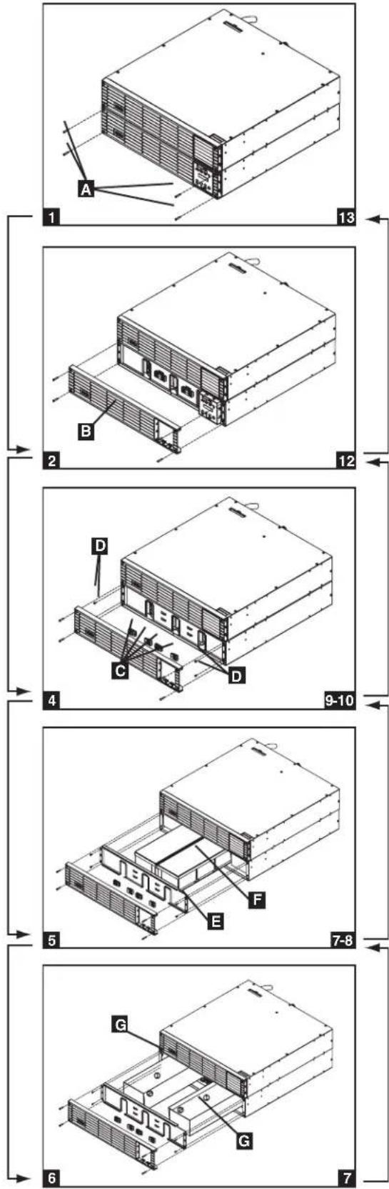
Internal Battery Replacement
Under normal conditions, the original batteries in your UPS will last many years. See Safety section before replacing batteries. The batteries are designed for hot-swap replacement (i.e. leaving the UPS ON), but some qualified service personnel may wish to completely turn the UPS OFF and disconnect equipment before proceeding. It is suggested that you remove the batteries before the installation process.
1 Remove the screws A which secure the front bezel.
2 Separate the front bezel B from the front panel.
3 Remove the battery connector snap covers. Save these covers for reuse.
4 Disconnect the battery connectors C and remove the screws D that secure the battery retention bracket in place.
5 Remove the battery retention bracket E and remove/ recycle the middle battery pack F.
6 Remove/recycle the side battery packs G.
7 Replace the battery packs F and G.
8 Re-attach the battery retention bracket E.
9 Replace the screws D to secure the battery retention bracket in place.
10 Connect the battery connectors C. Attach connectors black-to-black, red-to-red, white-to-white and green-to-green.
11 Reinstall the battery connector snap covers.
12 Replace the front bezel B.
⑬ Replace the screws A to secure the front bezel in place.
Storage and Service
Storage
Before storing your UPS, turn it completely OFF. If you store your UPS for an extended period of time, recharge the UPS batteries for 4 to 6 hours once every three months. Note: after you connect the UPS to utility power, it will automatically begin charging its batteries. If you leave your UPS batteries discharged for an extended period of time, they will suffer a permanent loss of capacity.
Service
Your Tripp Lite product is covered by the warranty described in this manual. A variety of Extended Warranty and On-Site Service Programs are also available from Tripp Lite. For more information on service, visit www.triplite.com/support. Before returning your product for service, follow these steps:
- Review the installation and operation procedures in this manual to insure that the service problem does not originate from a misreading of the instructions.
- If the problem continues, do not contact or return the product to the dealer. Instead, visit www.tripplite.com/support.
- If the problem requires service, visit www.triplite.com/support and click the Product Returns link. From here you can request a Returned Material Authorization (RMA) number, which is required for service. This simple on-line form will ask for your unit's model and serial numbers, along with other general purchaser information. The RMA number, along with shipping instructions will be emailed to you. Any damages (direct, indirect, special or consequential) to the product incurred during shipment to Tripp Lite or an authorized Tripp Lite service center is not covered under warranty. Products shipped to Tripp Lite or an authorized Tripp Lite service center must have transportation charges prepaid. Mark the RMA number on the outside of the package. If the product is within its warranty period, enclose a copy of your sales receipt. Return the product for service using an insured carrier to the address given to you when you request the RMA.
Warranty
2-Year Limited Warranty
Seller warrants this product, if used in accordance with all applicable instructions, to be free from original defects in material and workmanship for a period of 2 years (except internal UPS system batteries outside USA and Canada, 1 year) from the date of initial purchase. If the product should prove defective in material or workmanship within that period, Seller will repair or replace the product, in its sole discretion. Service under this Warranty can only be obtained by your delivering or shipping the product (with all shipping or delivery charges prepaid) to: Tripp Lite; 1111 W.35th Street; Chicago IL 60609; USA.Seller will pay return shipping charges. Visit www.tripplite.com/support before sending any equipment back for repair.
THIS WARRANTY DOES NOT APPLY TO NORMAL WEAR OR TO DAMAGE RESULTING FROM ACCIDENT, MISUSE, ABUSE OR NEGLECT. SELLER MAKES NO EXPRESS WARRANTIES OTHER THAN THE WARRANTY EXPRESSLY SET FORTH HEREIN. EXCEPT TO THE EXTENT PROHIBITED BY APPLICABLE LAW, ALL IMPLIED WARRANTIES, INCLUDING ALL WARRANTIES OF MERCHANTABILITY OR FITNESS, ARE LIMITED IN DURATION TO THE WARRANTY PERIOD SET FORTH ABOVE; AND THIS WARRANTY EXPRESSLY EXCLUDES ALL INCIDENTAL AND CONSEQUENTIAL DAMAGES. (Some states do not allow limitations on how long an implied warranty lasts, and some states do not allow the exclusion or limitation of incidental or consequential damages, so the above limitations or exclusions may not apply to you. This Warranty gives you specific legal rights, and you may have other rights which vary from jurisdiction to jurisdiction).
Tripp Lite; 1111 W.35th Street; Chicago IL 60609; USA
WARNING: The individual user should take care to determine prior to use whether this device is suitable, adequate or safe for the use intended. Since individual applications are subject to great variation, the manufacturer makes no representation or warranty as to the suitability or fitness of these devices for any specific application.
PRODUCT REGISTRATION
Visit www.tripplite.com/warranty today to register your new Tripp Lite product. You'll be automatically entered into a drawing for a chance to win a FREE Tripp Lite product!* * No purchase necessary. Void where prohibited. Some restrictions apply. See website for details.
Regulatory Compliance Identification Numbers
For the purpose of regulatory compliance certifications and identification, your Tripp Lite product has been assigned a unique series number. The series number can be found on the product nameplate label, along with all required approval markings and information. When requesting compliance information for this product, always refer to the series number. The series number should not be confused with the marking name or model number of the product.
WEEE Compliance Information for Tripp Lite Customers and Recyclers (European Union)

Under the Waste Electrical and Electronic Equipment (WEEE) Directive and implementing regulations, when customers buy new electrical and electronic equipment from Tripp Lite they are entitled to:
- Send old equipment for recycling on a one-for-one, like-for-like basis (this varies depending on the country)
- Send the new equipment back for recycling when this ultimately becomes waste
UPS and Battery Recycling

Please recycle Tripp Lite Products. The batteries used in Tripp Lite products are sealed Lead-Acid batteries. These batteries are highly recyclable. Please refer to your local codes for disposal requirements.
You can call Tripp Lite for recycling info at 1-773-869-1234.
You can go the Tripp Lite Website for up-to-date information on recycling the batteries or any Tripp Lite product. Please follow this link: http://www.triplite.com/en/support/recycling-program.cfm
Tripp Lite follows a policy of continuous improvement. Product specifications are subject to change without notice.


Manufacturing Excellence
1111 W. 35th Street, Chicago, IL 60609 USA • www.tripplite.com/support
18-09-249 • 93-S2DC_revE
1111 W. 35th Street, Chicago, IL 60609 USA • www.tripplite.com/support
Características (Panel trasero)
Conexión opcional
Funcionamiento
![graph TD A["IPBYPASS"] --> B["Node"] C["AC/DCBATTERYDC/ACO/P"] --> D["Node"] B --> E["Node"] D --> F["Node"]](/content/2026/04/647283/images/dd9f5d7b3d388d60e6d5bd1f52d48c766162ed82382d1423b6749f932e288a01.jpg)
1111 W. 35th Street, Chicago, IL 60609 USA • www.tripplite.com/support
18-09-249 • 93-32DC_reVE
1111 W. 35th Street, Chicago, IL 60609 USA • www.tripplite.com/support
Branchement des barrettes de raccordement - Premier module PDU en câblé (SU6000RT4UHVVHW, SU6000RT4UTHFHW)
Raccordement (suite)
Raccordement facultatif

Utilisation
Messages de surcharge
1111 W. 35th Street, Chicago, IL 60609 USA • www.tripplite.com/support
1111 W. 35th Street, Chicago, IL 60609 USA • www.tripplite.com/support
Эксплуатация
1111 W. 35th Street, Chicago, IL 60609 USA • www.tripplite.com/support
- INTELLIGENT TRUE ON-LINE UPS SYSTEMS
- PROTECT YOUR INVESTMENT
- IMPORTANT SAFETY WARNINGS
- UPS LOCATION WARNINGS
- UPS CONNECTION WARNINGS
- EQUIPMENT CONNECTION WARNINGS
- MAINTENANCE WARNINGS
- BATTERY WARNINGS
- REQUIRED PROTECTIVE DEVICES AND CABLE CROSS-SECTIONS
- MOUNTING
- 4-POST MOUNTING
- 12KVA UPS CONFIGURATION—SU12KRT4UHW ONLY (USING 2 6KVA POWER MODULES)
- 2-POST MOUNTING (OPTIONAL)
- FEATURES
- POWER MODULE FRONT PANEL CONTROLS
- FEATURES (REAR PANEL) SEE "FEATURES" SECTION FOR FEATURE DESCRIPTIONS
- FEATURES (REAR PANEL) (CONTINUED) SEE "FEATURES" SECTION FOR FEATURE DESCRIPTIONS
- SU12KRT4UHW—12KVA UPS SYSTEM AND PARALLEL PDU MODULES
- FEATURES (REAR PANEL) (CONTINUED)
- CONNECTION
- 1 PLUG YOUR UPS'S INPUT CORD INTO AN ELECTRICAL OUTLET. (SU5000RT4UHV, SU5000RT4UTF, SU6000RT4UHV, SU6000RT4UTF)
- 2 TURN UPS ON
- 3 PLUG YOUR EQUIPMENT INTO YOUR UPS
- 4 TURN UPS OFF (OPTIONAL)
- 5 UPS COLD START (OPTIONAL)
- TERMINAL STRIP INPUT CONNECTIONS
- (SU6000RT4UHVHW, SU6000RT4UHVG, SU6000RT4UTFHW)
- HARDWIRING CAUTIONS
- CONNECTION (CONTINUED)
- TERMINAL STRIP CONNECTION—IEC PDU MODULE (SU6000RT4UHVG)
- TERMINAL STRIP CONNECTION—HARDWIRE PDU MODULE (SU6000RT4UHVHW, SU6000RT4UTHFHW)
- HARDWIRING THE TRANSFORMER BUNDLE (INPUT/OUTPUT)
- SU6000RT4UTF
- SU12KRT4UHW
- OPTIONAL CONNECTION
- 1 RS-232 SERIAL AND USB COMMUNICATION CONNECTIONS
- 2 EPO PORT CONNECTION
- NOTE
- OPTIONAL CONNECTION (CONTINUED)
- LEDS OUTPUT FANS SERIAL SNMP USB LCD SCREEN
- 3 EXTERNAL BATTERY CONNECTION
- 4 ACCESSORY SLOT
- HOT-SWAP POWER MODULE REPLACEMENT
- UPS REMOVAL (6KVA SINGLE UPS POWER MODULE CONFIGURATIONS ONLY)
- WARNING! HIGH VOLTAGE! RISK OF ELECTRICAL SHOCK
- OPERATION
- LED DISPLAY INFORMATION
- OPERATION (CONTINUED)
- STARTUP SELF-TEST
- FAILED SELF-TEST
- NORMAL OPERATION
- UPS SETUP MENU
- CHANGING THE PASSWORD
- SELECTING SCREEN LANGUAGE
- START SETTINGS
- CHARGER SETTINGS
- UPS CHARGE CURRENT SETTINGS FOR THE 12KVA MODEL
- BATTERY SETTINGS
- OUTPUT SETTINGS
- UPS ALARM LOG
- SELF DIAGNOSIS INFORMATION
- ON BATTERY ALARM
- OVERLOAD MESSAGES
- BYPASS MESSAGES
- SHUTDOWN MESSAGES
- INTERNAL BATTERY REPLACEMENT
- STORAGE AND SERVICE
- STORAGE
- SERVICE
- WARRANTY
- 2-YEAR LIMITED WARRANTY
- PRODUCT REGISTRATION
- REGULATORY COMPLIANCE IDENTIFICATION NUMBERS
- WEEE COMPLIANCE INFORMATION FOR TRIPP LITE CUSTOMERS AND RECYCLERS (EUROPEAN UNION)
- UPS AND BATTERY RECYCLING
- CARACTERÍSTICAS (PANEL TRASERO)
- CONEXIÓN OPCIONAL
- FUNCIONAMIENTO
- BRANCHEMENT DES BARRETTES DE RACCORDEMENT - PREMIER MODULE PDU EN CÂBLÉ (SU6000RT4UHVVHW, SU6000RT4UTHFHW)
- RACCORDEMENT (SUITE)
- RACCORDEMENT FACULTATIF
- UTILISATION
- MESSAGES DE SURCHARGE
- ЭКСПЛУАТАЦИЯ
Brand : Tripp Lite
Model : SU6000RT4UHVPM
Category : Inverter