
SU10000RT3UPM - Inverter Tripp Lite - Free user manual and instructions
Find the device manual for free SU10000RT3UPM Tripp Lite in PDF.
User questions about SU10000RT3UPM Tripp Lite
0 question about this device. Answer the ones you know or ask your own.
Ask a new question about this device
Download the instructions for your Inverter in PDF format for free! Find your manual SU10000RT3UPM - Tripp Lite and take your electronic device back in hand. On this page are published all the documents necessary for the use of your device. SU10000RT3UPM by Tripp Lite.
USER MANUAL SU10000RT3UPM Tripp Lite
Intelligent True On-Line UPS Systems (Rack-Mount/Tower)
- Includes power module, external battery module and PDU
- Detachable PDU features outlets and maintenance bypass switch*
- Rack-Mount and tower adaptable
*An optional detachable hardwire PDU is available; contact Tripp Lite for details.
Not suitable for mobile applications.
Important Safety Warnings 2
Mounting 3
Features 4
Connection 6
Optional Connection 8
Manual Bypass Operation 9
Specifications 11
Operation 12
Storage and Service 26
Warranty and Product Registration 26
Español 27
Français 53
Русский 79
WARRANTY REGISTRATION
Register your product today and be automatically entered to win an ISOBAR ^® surge protector in our monthly drawing!
tripplite.com/warranty


text_image
TRIPP·LITE
1111 W. 35th Street, Chicago, IL 60609 USA • tripplite.com/support
Copyright © 2021 Tripp Lite. All rights reserved.
SAVE THESE INSTRUCTIONS.
This manual contains important instructions and warnings that should be followed during the installation and maintenance of all Tripp Lite SmartOnline Rack-Mount/Tower UPS Systems and their batteries.
UPS Location Warnings
• Install your UPS indoors, away from excess moisture or heat, direct sunlight, dust and conductive contaminants.
• Install your UPS in a structurally sound area. Your UPS is extremely heavy; take care when moving and lifting the unit.
- Only operate your UPS at indoor temperatures between 32^ and 104^ (between 0^ and 40^ ). For best results, keep indoor temperatures between 62^ and 84^ (between 17^ and 29^ ).
- Leave adequate space around all sides of the UPS for proper ventilation.
- Do not install the UPS near magnetic storage media, as this may result in data corruption.
- Do not mount unit with its front or rear panel facing down (at any angle). Mounting in this manner will seriously inhibit the unit's internal cooling, eventually causing product damage not covered under warranty.
UPS Connection Warnings
• Isolate the UPS before working on this circuit.
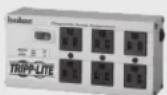
- Required Protective Devices and Cable Cross-Sections. Recommended upstream protection.
| UPS Power Rating Upstream Circuit Breaker | |
| 8kVA | D curve 50A |
| 10kVA | D curve 60A |
text_image
2 poles circuit breaker L1 L2(N) To UPS Normal AC source G L2(N)L 1- The power supply for this unit must be single-phase rated in accordance with the equipment nameplate. It also must be suitably grounded.
text_image
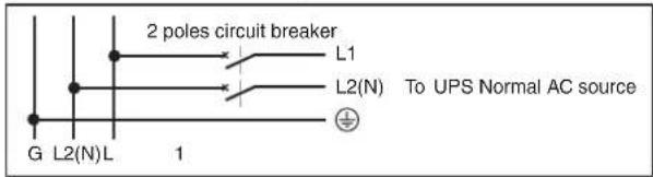
External power distribution unit L N Q T B UPS Legend. B Contactor solenoid. Q Mains input thermal-magnetic switch T Two-pole contactor 100 A AC1; coil voltage: according to the mains input.Remark: Q needs to use the approved component of Safety Certification.
Equipment Connection Warnings
- Use of this equipment in life support applications where failure of this equipment can reasonably be expected to cause the failure of the life support equipment or to significantly affect its safety or effectiveness is not recommended.
- Connect your UPS power module's grounding terminal to a grounding electrode conductor.
- The UPS is connected to a DC energy source (battery). The output terminals may be live when the UPS is not connected to an AC supply.
Maintenance Warnings
- Your UPS power module and battery module(s) do not require routine maintenance. Do not open them for any reason. There are no user-serviceable parts inside.
Battery Warnings
- Do not operate your UPS without connecting it to an external battery module.
- Connect only Tripp Lite battery modules to your UPS power module's external battery connector.
- Batteries can present a risk of electrical shock and burn from high short-circuit current. Observe proper precautions. Do not dispose of the batteries in a fire. Do not open the UPS or batteries. Do not short or bridge the battery terminals with any object. Unplug and turn off the UPS before performing battery replacement. Use tools with insulated handles. There are no user-serviceable parts inside the UPS. Battery replacement should be performed only by authorized service personnel using the same number and type of batteries (Sealed Lead-Acid). The batteries are recyclable. Refer to your local codes for disposal requirements or visit triplite.com/support/recycling-program for recycling information. Tripp Lite offers a complete line of UPS System Replacement Battery Cartridges (R.B.C.).Visit Tripp Lite on the Web at triplite.com/products/battery-finder/ to locate the specific replacement battery for your UPS.
- Do not open or mutilate the batteries. Released electrolyte is harmful to the skin and eyes, and may be toxic.
- Fuses should be replaced only by factory authorized personnel. Blown fuses should be replaced only with fuses of the same number and type.
- Service and repair should be done only by trained personnel. During any service work to the UPS, it should be turned off or manually bypassed via the transformer. Note that potentially lethal voltages exist within this unit as long as the battery supply is connected.
- Do not connect or disconnect battery module(s) while the UPS is operating from the battery supply or when the detachable PDU is not in bypass mode.
- During "hot-swap" battery module replacement your UPS will be unable to provide battery backup in the event of a blackout.
- Only connect compatible battery module(s).
Mounting (Rack)
Mount your equipment in either a 4-post or 2-post rack or rack enclosure. The user must determine the fitness of hardware and procedures before mounting. If hardware and procedures are not suitable for your application, contact the manufacturer of your rack or rack enclosure. The procedures described in this manual are for common rack and rack enclosure types and may not be appropriate for all applications.
Note: The power module and battery module must be installed in separate shelves.
4-Post Mounting
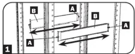
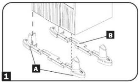
1 The included plastic pegs A will temporarily support the empty rack-mount shelves B while you install the permanent mounting hardware. Insert a peg near the center of the front and rear bracket of each shelf as shown (each front bracket has 6 holes and each rear bracket has 3 holes). The pegs will snap into place.
After installing the pegs, expand each shelf to match the depth of your rack rails. The pegs will fit through the square holes in the rack rails to support the shelves. Refer to the rack unit labels to confirm that the shelves are level in all directions.
Note: The support ledge of each shelf must face inward.
2 Secure the shelves B to the mounting rails permanently using the included screws and cup washers C as shown.
- For 2U equipment mounting, place 4 screws total at the front and 4 screws total at the back.
- For 3U equipment mounting, place 6 screws total at the front and 4 screws total at the back.
Tighten all screws before proceeding.
Warning: Do not attempt to install your equipment until you have inserted and tightened the required screws. The plastic pegs will not support the weight of your equipment.
3 Attach mounting ears D to the front mounting holes of your equipment E using the screws provided F. The ears should face forward.
4 Using an assistant, lift your equipment and slide it onto the mounting shelves. Attach your equipment to the rack by passing the screws, nuts and washers (user-provided) through its mounting ears and into the rack rails.
5 (Optional) Attach 2 PDU hanger brackets to the right-side, rear mounting rail using included screws and cage nuts. Important: determining where to attach your PDU hanger brackets will depend on your rack configuration. Generally it is recommended to mount the top bracket in the bottom two square holes of the U space that the UPS and PDU are mounted in. The second bracket should be installed 3U measures down and placed in the top two square holes of the U. (For example: If the PDU and UPS are mounted in 7U, the first bracket will be installed in the bottom two square holes of 7U. The second bracket would be installed in the top two square holes of 4U.
text_image
B A A B A 1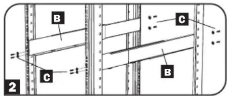
text_image
B C B 2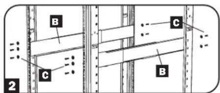
text_image
B C B 2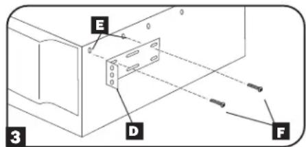
text_image
E D F 3
text_image
TRIPEFLUE G 4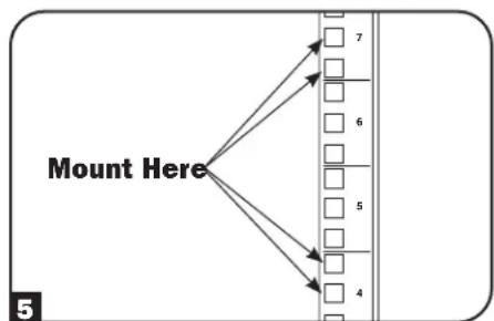
flowchart
graph TD
    A["Mount Here"] --> B["7"]
    A --> C["6"]
    A --> D["5"]
    A --> E["4"]
    B --> F
    C --> G
    D --> H
    E --> I
2-Post Mounting (Optional)
To mount your equipment in a 2-post rack, you must purchase a Tripp Lite 2-Post Rackmount Installation Kit (model: 2POSTRMKITWM, sold separately) for each module installed. See the Installation Kit's owner's manual for complete mounting instructions.
Mounting (Tower)
Mount all modules in an upright, tower position using the included base stands. The user must determine the fitness of hardware and procedures before mounting.
1 The UPS system is shipped with two sets of plastic feet A and extensions B that can be used to tower mount the UPS power module, a battery module and a second battery module (9U total).
Adjust the feet to a width of 10.25 inches (26 cm) for a UPS power module and battery module, or to a width of 15.375 inches (39 cm) for three units. Align the feet in your installation area, approximately 10 inches (26 cm) apart. Have one or more assistants help you place the units on their sides in the feet. The control panel of the UPS should be the upper corner of the UPS and face outward.
2 Rotate the power module's Control Panel to view it easier while the UPS is tower mounted. Insert a small screwdriver, or other tool, in the slots on either side of the Control Panel. Pop the panel out, rotate it, then pop the panel back into place.
text_image
A B 1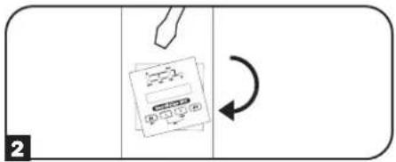
flowchart
graph TD
    A["Document Icon"] --> B["Arrow"]
    B --> C["Return Arrow"]
Features
Before installing and operating your UPS, familiarize yourself with the location and function of the features of each component.
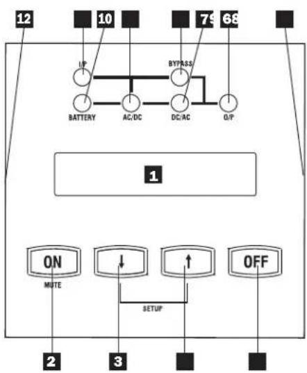
Power Module Front Panel Controls
1 LCD SCREEN: This backlit (16 × 2 character) dot matrix display indicates a wide range of UPS operating conditions and diagnostic data. It also displays UPS settings and options when the UPS is in setup mode.
2 ON/MUTE BUTTON: Press this button and hold it until you hear a beep to turn the UPS system's inverter ON. If the UPS battery alarm is sounding, press this button to silence it.
3 SCROLL DOWN/EXIT SETUP BUTTON: This button allows you to browse through different options and power readings on the LCD screen. Momentarily pressing it causes the LCD screen to display a different power reading (see "Operation", pg. 12). Pressing it and the SCROLL UP Button together puts the UPS in setup mode, where this button is used to scroll through setup options and to exit setup mode.
4 SCROLL UP/SELECT BUTTON: This button allows you to browse through different options and power readings on the LCD screen. Momentarily pressing it causes the LCD screen to display a different power reading (see "Operation Section", pg. 17). Pressing it and the SCROLL DOWN Button together puts the UPS in setup mode, where this button is used to select setup options.
5 OFF BUTTON: Press this button until you hear a beep to turn the UPS system's inverter OFF.
6 O/P (OUTPUT) LED: This green light will illuminate to indicate your UPS is supplying AC power to connected equipment.
7 DC/AC (INVERTER) LED: This green light will illuminate to indicate the UPS DC/AC inverter is activated.
8 BYPASS LED: This green light will illuminate when the UPS is providing filtered mains power without engaging its converter or inverter. If this LED is illuminated, connected equipment will not receive battery power in the event of a blackout, unless the Economy Mode feature is enabled.
9 AC/DC (Converter) LED: This green light will illuminate to indicate the UPS AC/DC converter is charging the connected battery pack(s).
10 BATTERY LED: This green light will illuminate when the UPS is discharging the battery to provide connected equipment with AC power. An alarm will sound which can be silenced by pressing the ON/MUTE Button. This LED will remain illuminated after the alarm is silenced.
11 I/P (INPUT) LED: This green light will illuminate to indicate an AC input supply is present.
12 ACCESS SLOTS: To rotate the controls, insert a flathead screwdriver into these slots and gently lever the panel out. Taking care not to excessively twist or yank the cables connecting the controls to the rest of the UPS, Turn the controls to the desired orientation and reinsert them.
flowchart
graph TD
    A["UP"] --> B["BATTERY"]
    B --> C["AC/DC"]
    C --> D["BYPRESS"]
    D --> E["DC/AC"]
    E --> F["O/P"]
    G["ON MUTE"] --> H["SETUP"]
    I["↑"] --> H
    J["OFF"] --> H
    style A fill:#f9f,stroke:#333
    style B fill:#ccf,stroke:#333
    style C fill:#ccf,stroke:#333
    style D fill:#ccf,stroke:#333
    style E fill:#ccf,stroke:#333
    style F fill:#ccf,stroke:#333
    style G fill:#dfd,stroke:#333
    style H fill:#dfd,stroke:#333
    style I fill:#dfd,stroke:#333
    style J fill:#dfd,stroke:#333
Features (Rear Panel) See page 6 for feature descriptions
8kVA/10kVA Power Module
text_image
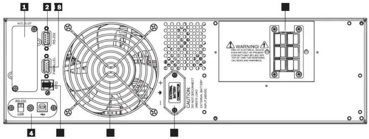
1 2 8 ACO. SLOT RS-232 PARALLEL EPO RS-232 USB 4 CAUTION: DO NOT DISCONNECT UNDER LOAD EXTERNAL BATTERY CONNECTION EXTERNAL BATTERY NPL-IT 240VDC WARNING! REX OF ELECTRICAL SHOCK EVEN WITHOUT AC PRESENT CONTACTS MAY BE LIKE SEE TOP OF UNIT FOR ADDITIONAL CAUTIONS AND WARNINGS.Detachable Power Distribution Unit

text_image
12 11 REMOVE TO RESET/ABS BUTTON 30A 30A 28A 28A 28A/240V~ 28B/240V~ 28B/240V~ 28B/240V~ INCH INPUT BOX CONNECTOR 9Battery Module
text_image
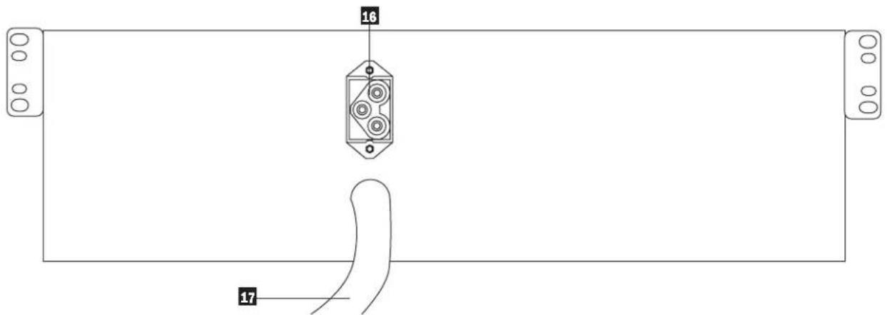
16 17Features (Rear Panel)
Power Module Feature Description
1 Accessory Slot: Remove the small cover panel to install optional accessories to remotely control and monitor your UPS system. Visit Tripp Lite on the Web (www.triplite.com) to learn about available SNMP, network management and connectivity products that may be installed in this slot.
2 RS-232 Communication Port: This female DB9 serial port may be used to connect your UPS to a workstation or server. It uses RS-232 protocol to communicate with a connected computer. It is used with Tripp Lite software and the included serial cable to monitor and manage the UPS remotely over a network and to automatically save open files and shut down equipment during a blackout. See “Optional Connection” for details. An optional Contact-Closure card is available if needed (Tripp Lite part # RELAYIOCARD).
3 Parallel Connector: For UPS communication in parallel.
4 USB Communication Port: The USB port may be used to connect your UPS to a workstation or server. It is used with Tripp Lite software and the included USB cable to monitor and manage the UPS remotely over a network and to automatically save open files and shut down equipment during a blackout. See "Optional Connection" for details. For USB communications, both DIP switches must be in the ON position. This will disable the RS-232 port.
5 EPO (Emergency Power Off) Port: Used to connect the power module to a contact closure switch to enable emergency power off. See "Optional Connection" section for details.
6 Exhaust Fan: This cools and ventilates the inside of the power module.
7 External Battery Connector: Use this to connect one or more Tripp Lite battery modules to the power module. Remove the cover for access. The power module will not start without a connection to a charged battery module. Refer to the battery module owner's manual for connection instructions and safety warnings.
8 Input Terminal Block: Use these terminals to connect your power module to the detachable PDU.
Detachable Power Distribution Unit Feature Description
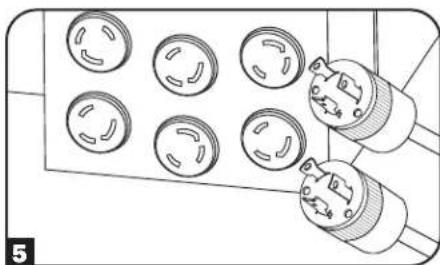
9 AC Output Receptacles: Accept direct plug-in connection of NEMA L6-30P or NEMA L6-20P equipment plugs.
10 AC Output Breakers: Control output power to the PDU's AC output receptacles.
11 Maintenance Bypass Switch: Permits qualified service personnel to remove the PDU from the power module for routine maintenance without disrupting power to the load. When this switch is set to BYPASS the load will receive unfiltered AC utility power and no battery backup power will be available in the event of a blackout. See the "Manual Bypass Operation" section for detailed manual bypass procedures. WARNING! For qualified service personnel only. If the complete bypass procedure (see "Manual Bypass Operation," p. 10) is not followed, the UPS will not be adequately powered down, presenting a risk of death or serious injury from contact with high voltage.
12 Utility Input Terminal Block: Use these terminals to connect the PDU to utility power. To access the terminals, unscrew and remove the terminal block cover.
13 Power Module Input Terminal Box: Use these terminals to connect the PDU to the Power Module.
14 Sliding Cover for Power Module Input Terminals: Slide this cover over the terminals after detaching the PDU from the Power Module during Manual Bypass Operation (p. 10).
15 Input Terminal Block Cable Access: Located on the left side of the PDU.
Battery Module Feature Description
16 Input Connector: Use this connector to daisy chain additional battery modules onto the first. Remove the cover panel for access. Refer to the battery module owner's manual for connection instructions and safety warnings.
17 Output Cable: Use this cable to connect the battery module to the power module or to another battery module. The power module will not start without a connection to a charged battery module. Refer to the battery module owner's manual for connection instructions and safety warnings.
Connection
HardwiringCautions
- Wiring must be done by a qualified electrician.
- When making wiring connections, observe the cable connection regulations appropriate to your area [e.g. National Electrical Code (NEC) in the U.S.] at all times. Be sure to install an easily accessible disconnect switch in your installation wiring so you may cut off the UPS AC input during fires and other emergencies. Ensure that cables are fitted with cable sleeves and are secured by connector clamps. Tighten connections with a torque of not less than 24-28 inch-pounds (2.7-3.2 NM).
- Make sure that your equipment is properly grounded.
- Using cables of improper size may damage your equipment and cause fire hazards. Choose appropriate cabling and protection circuits to make wiring connections. Ground conductors must be the same size and type as the power conductors used.
• Refer to National Electrical Code (NEC) guidelines for proper wire gauge and output protection circuit requirements.
| Input and Output Ratings | ||||
| Model | Input Voltage | Maximum Rated Input Current | Maximum Rated Output Current | Typical Wire Size |
| 8kVA | 208~240V (L-N) | 46 A | 40 A | 8 mm^2 = 8AWG |
| 10kVA | 208~240V (L-N) | 56 A | 50 A | 8 mm^2 = 8AWG |
Connection
Connecting Modules to Each Other and to Utility Power and Equipment
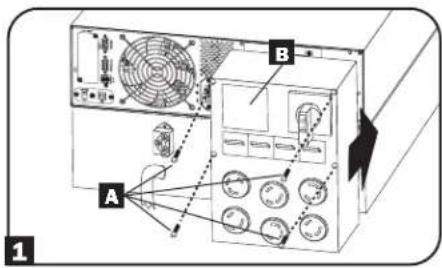
1 Attach the PDU to the Power Module and Battery Module.
Align and connect the PDU's power module input terminals with the terminals on the back of the Power Module. Secure the PDU to the Power Module with four screws A. Before proceeding further, ensure that the Bypass Switch is set to NORMAL. Remove the utility input terminal block cover B.
2 Hardwire the PDU to a Utility Power Source.
Pass a user-supplied cable through the knockout on the left side of the PDU C and connect it to the PDU's input terminals D. Replace the terminal block cover. Connect the other end of the cable to a utility power source.
3 Connect the battery module to the power module.
Consult the owner's manual that came with your battery module. Fully insert the connector on the end of the battery module's cable E into the connector on the rear panel of the power module F. Small sparks may occur; this is normal.
Note: The power module does not contain internal batteries and will not start until a battery module is connected.
The battery modules are fully charged prior to shipping. However, before expecting full backup capability (particularly if the battery module has been stored for an extended period) after the UPS system is connected to a utility power source, allow the battery module to recharge for 12 hours. Once the UPS system is in use, it will charge the batteries and maintain the charge level automatically. If needed, connect additional battery modules in a daisy-chain with each module's cable inserted into the previous module's connector G.
Contacts on Power/Battery Module WARNING! High Voltage! Risk of electrical shock!
Due to the presence of high voltage internal batteries, even without AC present, these contacts are live
Do not let these contacts touch any surface!
Contacts on Detachable PDU WARNING! High voltage! Risk of electrical shock! If AC is present and Bypass Switch is set to "Bypass", these contacts are live! Do not let these contacts touch any surface!
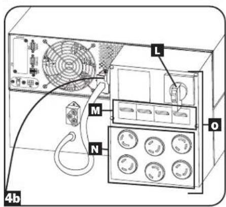
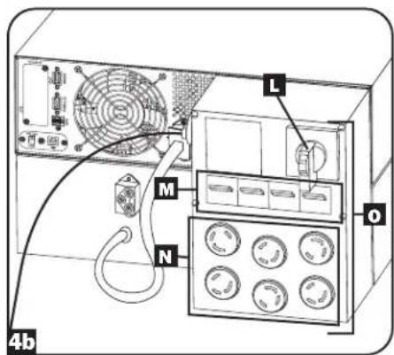
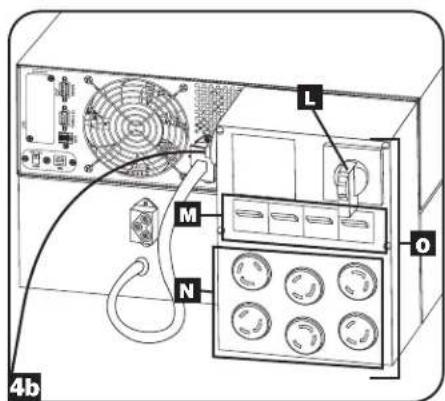
4 Turn UPS ON
Note: The UPS system will function properly upon initial startup. However, maximum runtime for the unit's battery will only be accessible after it has been charged for 24 hours.
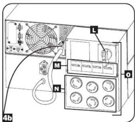
- Turn on the breaker for the UPS system's utility power source. This will energize the UPS power module and the control panel's LCD screen ⚠ will display "BYPASS MODE".
- Make sure the PDU module's manual bypass switch L is in the "NORMAL" position.
- Turn on the PDU output circuit breakers M.
- Configure the UPS system in SETUP MODE. Enter SETUP MODE by holding down both scroll buttons 🖼 at the same time.
- Scroll through the setup options (using the scroll buttons 📁) and press the "SELECT" button 🔒 to select the appropriate settings:
Input & Output Voltage: Select 200, 208, 220, 230, or 240V AC.
Output Frequency: The UPS system will auto-select 50 or 60 Hz to match the input.
Economy Mode: The UPS system can provide on-line operation with zero transfer time. It can also operate in a more energy-efficient, line-interactive mode. Select "ECONOMY ON" for line-interactive mode. Select "ECONOMY OFF" for on-line mode.
-
After configuring the options, exit SETUP MODE with the scroll buttons
-
Press the control panel's "ON" button □ until the UPS system beeps, then release the button.
-
The UPS system will perform a brief self-test and show the results on the control panel LEDs and LCD screen H. See "Startup Self-Test" in the "Operation" section for the display sequence.
-
After the self-test is complete, the LCD screen H should display "ONLINE MODE" or "ECONOMY MODE", depending on which option was selected. The UPS system is now turned on.
text_image
A B 1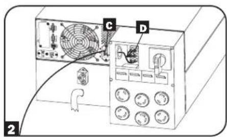
text_image
Diagram of a computer power supply unit with labeled components including fan, buttons, and control panel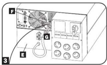
text_image
F G E 3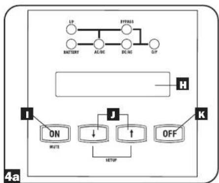
flowchart
graph TD
    A["UP"] --> B["BATTERY"]
    B --> C["AC/DC"]
    C --> D["DC/AC"]
    D --> E["GTP"]
    F["H"] --> G["Input Box"]
    G --> H["I"]
    H --> I["ON MUTE"]
    H --> J["J"]
    J --> K["SETUP"]
    K --> L["OFF"]
    L --> M["K"]
text_image
L M N 4b OConnection
5 Plug Your Equipment into the PDU's Outlets
Your UPS is designed to support electronic equipment only. You will overload your UPS if the total VA rating for all the equipment you connect exceeds the UPS's output capacity. Do not connect household appliances or laser printers to the UPS outlets. To find your equipment's VA ratings, look on their nameplates. If the equipment is listed in amps, multiply the number of amps by the input voltage (240V or 208V) to determine VA. (Example: 1 amp × 120 = 120 VA).
6 Turn UPS OFF (Optional)
- Press the control panel's "OFF" button K until you hear a beep, then release the button. The LCD screen H will display "BYPASS MODE". The inverter is now turned off, but the UPS system is not fully deactivated and the load is still energized.
- Turn off the Output Circuit Breakers M located on the detachable PDU. The load will no longer be energized and the LCD screen H will be dark.
- Turn off the breaker for the UPS system's utility power source. The UPS system is now turned off and the LCD screen H will be dark.
7 UPS Cold Start (Optional)
During a blackout or other input power failure, the UPS system can be "cold started" from battery. (The battery must be at least partially charged.)
Note: The UPS system's output settings cannot be configured while operating from battery. It will use the previously configured output settings.
- Make sure the PDU modules manual bypass switch L is set to the "NORMAL" position.
- Turn on the Output Circuit Breakers on PDU module M.
- Press the control panel's "ON" button until the UPS system beeps, then release the button. The UPS system's inverter will begin to operate.
Note: Some electronic equipment draws more current at startup. When starting from battery, consider reducing the initial load. - The UPS system will perform a brief self-test and show the results on the control panel LEDs and LCD screen H. See "Startup Self-Test" in the "Operation" section for the display sequence.
- After the self-test is complete, the LCD screen H should display "ON BATTERY MODE" and an alarm should sound.
- The UPS system will now provide power to connected equipment until the battery is discharged.
natural_image
Diagram of a multi-pin electrical plug with six circular components and connectors (no text or symbols)Optional Connection
The following connections are optional. Your UPS system will function properly without these connections.
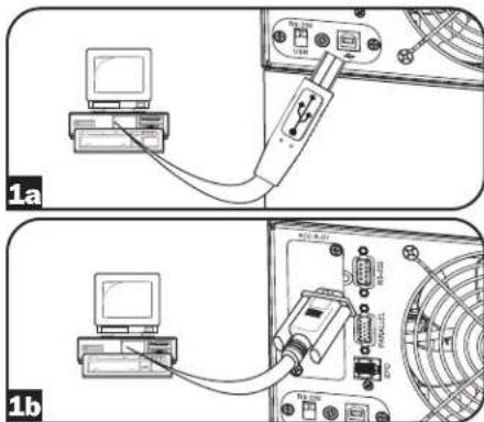
1 USB and RS-232 Serial Communication Connection
Use the included USB cable 1a or RS-232 DB9 serial cable 1b to connect the communication port of your computer to the communication port of your UPS. Install on your computer the Tripp Lite PowerAlert Software appropriate to your computer's operating system. Consult your PowerAlert manual for more information.
USB Communication Port Note: The USB port may be used to connect your UPS to a workstation or server. It is used with Tripp Lite software and the included USB cable to monitor and manage the UPS remotely over a network and to automatically save open files and shut down equipment during a blackout. See "Optional Connection" for details. For USB communications, both DIP switches must be in the ON position. This will disable the RS-232 port.
text_image
1a 1bOptional Connection
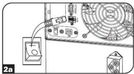
2 EPO Port Connection
This optional feature is only for those applications that require connection to a facility's Emergency Power Off (EPO) circuit. When the UPS is connected to this circuit, it enables emergency shutdown of the UPS inverter and inhibits transfer to internal bypass. Using the cable provided, connect the EPO port of your UPS (see 2a) to a user-supplied normally closed or normally open switch according to the circuit diagram (see 2b).
Notes:
-
If using a cable other than what is supplied, the cable should not exceed 350 feet or have a resistance of greater than 10 ohms.
-
If a non-latching EPO switch is used, the EPO must be held for a minimum of 1 second. This does not apply to a latching EPO switch.
CAUTION: The EPO port is not a phone line surge protector. Do not connect a phone line to this port.
UPS Unit State when asserting EPO with AC line present:
| LEDs Output Fans | Serial SNMP USB LCD Screen | ||
| OFF OFF OFF OFF OFF “Emergency Stop” |
To restart the UPS unit after asserting EPO with AC line present:
- Verify that the EPO assertion has been removed or cleared.
- Remove AC line power to the UPS unit.
- Reapply AC line power. Now the UPS will start back up in Bypass mode and the LCD will display "BYPASS MODE".
UPS Unit State when asserting EPO without AC line power:
| LEDs Output Fans | Serial SNMP USB LCD Screen | ||
| OFF OFF OFF OFF OFF OFF “Emergency Stop” |
To restart the UPS unit after asserting EPO without AC line power:
- Verify that the EPO assertion has been removed or cleared.
- Reapply AC line power to the UPS unit. Now the UPS will start back up in Bypass mode and the LCD will display "BYPASS MODE".
3 Internal SNMP/WEB Card Insertion
Remove the small cover panel from the accessory slot to use optional accessories to remotely monitor and control your UPS. Visit www.tripplite.com/support for more information, including a list of available SNMP, network management and connectivity products.
natural_image
Diagram of an electronic device with a power outlet connected to a fan and ports (no text or symbols visible)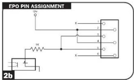
text_image
EPO PIN ASSIGNMENT 12V 1K X 1 2 3 4 5 6 2b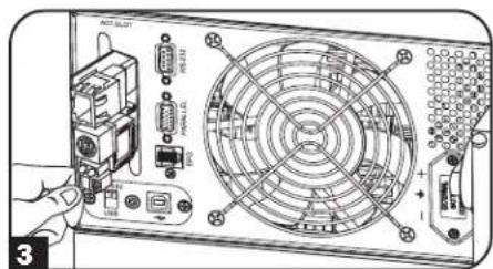
text_image
ACT.SLOT RS-22 POWER.LG + - 3Manual Bypass Operation (for power module maintenance or replacement)
The UPS system includes a self-contained power/battery module along with an independent, detachable PDU with a bypass switch. This switch allows qualified service personnel to remove the detachable PDU from the power/battery module for routine maintenance without disrupting power to connected loads. While this switch is set to "BYPASS", connected equipment will receive unfiltered AC utility power, but the equipment will not receive battery power in the event of a blackout.
Note: If desired, an optional hardwire detachable PDU is also available separately from Tripp Lite. Contact Tripp Lite for details.
(Optional: During a hot-swap, the PDU can be housed in the back of the rack configuration using supplied PDU hanger brackets and hardware. See STEP 5 on page 3 for mounting instructions.)
WARNING! For qualified service personnel only. Failure to follow the bypass procedure completely will not adequately power down the UPS power/battery module, resulting in the continued risk of death or injury from potential contact with high voltage. The UPS's power/battery module and detachable PDU are extremely heavy. This procedure requires several people to perform.
Manual Bypass Operation (for power module maintenance or replacement)
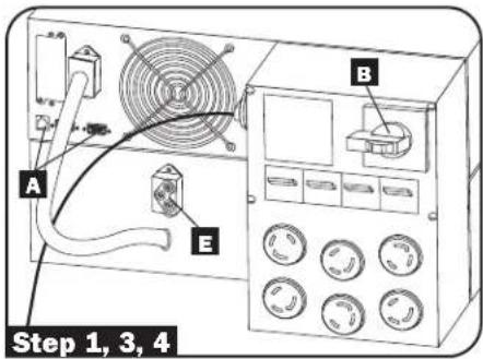
UPS Power/Battery Module Removal
STEP 1. Disable PowerAlert Software and disconnect communication cables from the communication ports A on the UPS power/battery module.
STEP 2. Press UPS "OFF" Button C, if the UPS is powered, until you hear a beep and see a "BYPASS MODE" message shown in the LCD Display
STEP 3. Turn the detachable PDU's Bypass Switch B to "BYPASS".
STEP 4. If an external battery module is connected to the UPS E, disconnect it from the UPS.
The UPS power/battery module is now safely powered down and it can be detached from the PDU to perform maintenance/replacement.

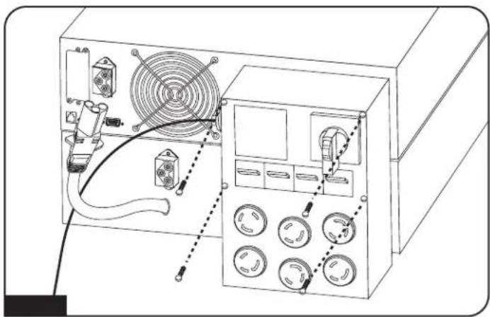
WARNING! High Voltage! Risk of electrical shock! SEE BELOW.

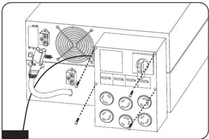
STEP 5: Remove the four screws that hold the detachable PDU to the power/battery module.
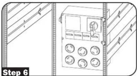
STEP 6: Using several assistants at each end, carefully pull the detachable PDU away from the power/battery module. During this process, ensure that each section is properly supported after they are separated. If the sections are detached in a rack-mount application, ensure that each section remains adequately supported by the UPS rack-mount rails. Remove the rack-mount hardware from the front panel of the UPS; slide the power and battery modules forward, and remove. If it is desired to leave the detached PDU in the rack, hang the unit in the back of the rack on the installed PDU hangers by the screws used to attach the PDU to the UPS system (refer to page 3 for PDU hanger bracket installation).
If the sections are detached in a tower application, ensure that the PDU is supported by the UPS tower feet. Adjust the tower feet so they are as close together as possible.
text_image
Step 1, 3, 4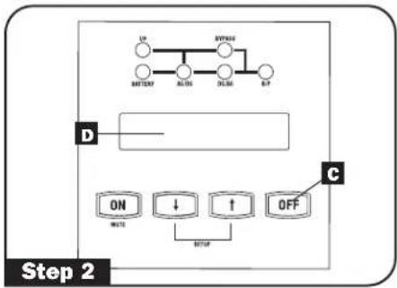
flowchart
graph TD
    A["BATTERY"] --> B["AC source"]
    B --> C["Voltage source"]
    C --> D["OUT"]
    D --> E["SET-up"]
    E --> F["ON"]
    E --> G["↓"]
    E --> H["↑"]
    E --> I["OFF"]
    J["D"] --> K["Control block"]
    K --> L["Step 2"]
natural_image
Technical line drawing of an electrical control panel with fan, buttons, and wiring (no text or labels)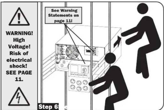
text_image
WARNING! High Voltage! Risk of electrical shock! SEE PAGE 11. See Warning Statements on page 11! Step 6STEP 7: Loosen the screws A in the contact cover B. Slide the cover over the contacts C Tighten the screw D to secure the cover. Warning: Use extreme caution when handling the PDU. Do not allow the contacts to touch any surface.
To reattach the PDU, reverse the process listed above.
natural_image
Technical line drawing of a mechanical control panel with buttons and gauges, enclosed in a structural frame (no text or symbols)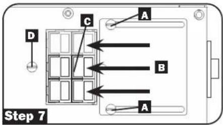
text_image
A B C D Step 7Contacts on Power/Battery Module

WARNING! High Voltage! Risk of electrical shock!

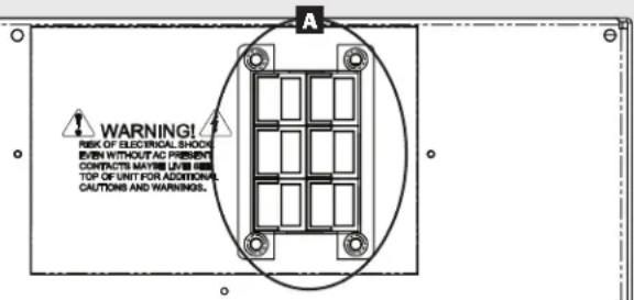
Due to the presence of high voltage internal batteries, even without AC present, these contacts A are live! Do not let these contacts touch any surface!
text_image
WARNING! RISK OF ELECTRICAL SHOCK EVEN WITHOUT AC PRESENT CONTRACTS MAY BE LIVES TOP OF UNIT FOR ADDITIONAL CAUTIONS AND WARNINGS.Contacts on Detachable PDU

WARNING! High voltage! Risk of electrical shock!

If AC is present and Bypass Switch is set to "Bypass", these contacts are live! Do not let these contacts touch any surface!

natural_image
Technical diagram of a device enclosure with internal grid layout and mounting points (no text or symbols)Specifications
The models listed below include a power module, one or two battery modules, and a PDU module.
| Model 8kVA 10kVA | ||
| Nominal voltage(s) and input range: 200 / 20 | 8 / 220 / 230 / 240 V~, 156-280V~ 200 / 208 / 220 / | 230 / 240 V~, 156-280V~ |
| Nominal input frequency and tolerance: 50/60 Hz (+/-6%) 50/60 Hz (+/-6%) | ||
| Rated output voltage: 200 / 208 / 220 / 230 / 240V~ 200 / 208 / 220 / 230 / 240V~ | ||
| Nominal output frequency: 50/60 Hz (+/-0.05 Hz) 50/60 Hz (+/-0.05 Hz) | ||
| Output voltage regulation in line mode: 200 / 208 / 220 / 230 / 240V~ (+/- 2%) 200 / 208 / 220 / 230 / 240V~ (+/- 2%) | ||
| Output voltage regulation in battery mode: 200 / 208 / 220 / 230 / 240V~ (+/- 2%) | 200 / 208 / 220 / 230 / 240V~ (+/- 2%) | 200 / 208 / 220 / 230 / 240V~ (+/- 2%) |
| Rated output power in W / VA: 7200W / 8000VA | 9000W / 10000VA | |
| Output voltage waveform: Sinusoidal in line mode and sinusoidal in battery mode | Sinusoidal in line mode and sinusoidal in battery mode | |
| Maximum output current @ P.F. | 40A @ 200V~ / 38.5A @ 208V~ / 36.4A @ 220V~ / 34.8A @ 230V~ / 33.3A @240V~ | 50A @ 200V~ / 48.1A @ 208V~ / 45.5A @ 220V~ / 43.5A @ 230V~ / 41.7A @ 240V~ |
| P.F. = 0.9 | P.F. = 0.9 | |
| Maximum harmonic distortion of the output voltage at full resistive load in battery mode: <3% | <3% | |
| Efficiency at rated load: 90% | 90% | |
| Maximum operating altitude at 100% rated power: 6561 ft. (2000 m) above the sea level | 6561 ft. (2000 m) above the sea level | |
| Online overload capacity: 105% continuous, 125% for 1 minutes, 150% for 30 seconds, >150% 0.5 seconds | 105% continuous, 125% for 1 minutes, 150% for 30 seconds, >150% 0.5 seconds | |
| Overload capacity in battery mode: 105% continuous, 125% for 1 minutes, 150% for 30 seconds, >150% 0.5 seconds | 105% continuous, 125% for 1 minutes, 150% for 30 seconds, >150% 0.5 seconds | |
| Current limitation Output: Varies by final bundled configuration bypass PDU | Output: Varies by final bundled configuration bypass PDU | |
| Autonomy time at full load: 5.5 minutes @ 7200W | 4.3 minutes @ 9000W | |
| Battery recharge time: 6 hours | 6 hours | |
| Transfer time: 0 milliseconds | 0 milliseconds | |
| Outlets: Varies by final soft bundle configuration | Varies by final soft bundle configuration | |
| Maximum input current: 46A / 44.2A / 41.8A / 40A / 38.3A | 56.1A / 54A / 51A / 48.8A / 46.8A |
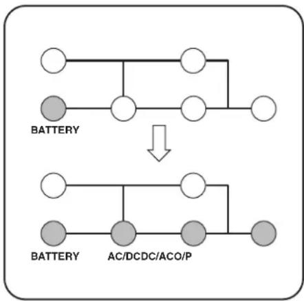
Operation
LED Display Information
AC Mode: AC input voltage in normal range: 156-280V.
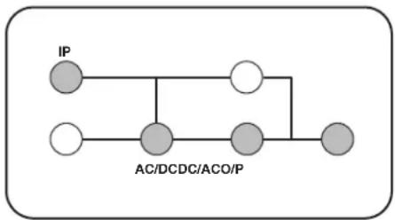
flowchart
graph TD
    A["IP"] --> B["Node"]
    C["AC/DCDC/ACO/P"] --> D["Node"]
    B --> E["Node"]
    D --> F["Node"]
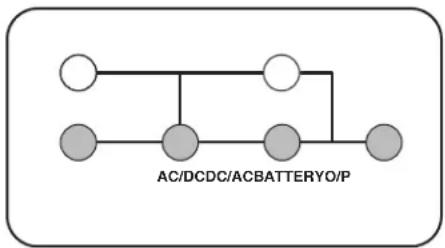
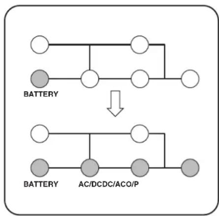
Cold Start/Battery Mode: With a cold start in Battery Mode, you will see the following LED display:
flowchart
graph TD
    A[" "] --> B[" "]
    B --> C[" "]
    C --> D[" "]
    D --> E[" "]
    style A fill:#fff,stroke:#000
    style B fill:#fff,stroke:#000
    style C fill:#fff,stroke:#000
    style D fill:#fff,stroke:#000
    style E fill:#fff,stroke:#000
    note bottom of E: AC/DCDC/ACBATTERYO/P
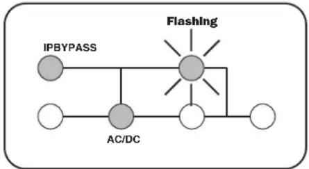
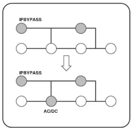
Bypass Mode: AC input voltage in a range of: -20 to +15% of the rating voltage; Bypass Mode is enabled.
flowchart
graph TD
    A["IPBYPASS"] --> B["Central Node"]
    C["AC/DC"] --> B
    B --> D["Flashing"]
    B --> E["White Circle"]
    B --> F["White Circle"]
    B --> G["White Circle"]
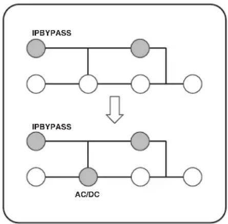
AC Power Start Up: With an AC power start up, you will see the following LED sequence:
flowchart
graph TD
    A["IPBYPASS"] --> B["AC/DC"]
    B --> C["Output"]
    D["Input"] --> E["Output"]
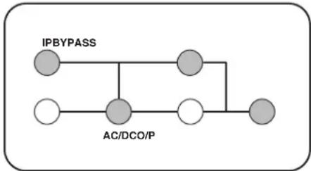
Economy Mode: AC input voltage in a range between -10 and +10% of rating voltage; Economy Mode is enabled.
flowchart
graph TD
    A["IPBYPASS"] --> B["Gray Node"]
    B --> C["Gray Node"]
    C --> D["Gray Node"]
    D --> E["Gray Node"]
    F["AC/DCO/P"] --> G["Gray Node"]
    G --> H["Gray Node"]
    H --> I["Gray Node"]
Cold Start: With a cold start, you will see the following LED sequence.
flowchart
graph TD
    A[" "] --> B[" "]
    B --> C[" "]
    C --> D[" "]
    E[" "] --> F[" "]
    F --> G[" "]
    G --> H[" "]
    I["BATTERY"] --> J["↓"]
    K["BATTERY"] --> L["AC/DCDC/ACO/P"]
    L --> M[" "]
Operation
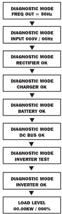
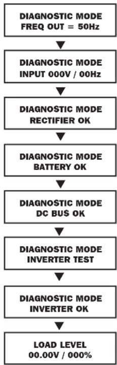
Startup Self-Test
When you turn the UPS ON, it will enter Diagnostic Mode and perform a brief self-test lasting about 15 seconds. The results of the self-test are shown on the LCD screen in the sequence below.
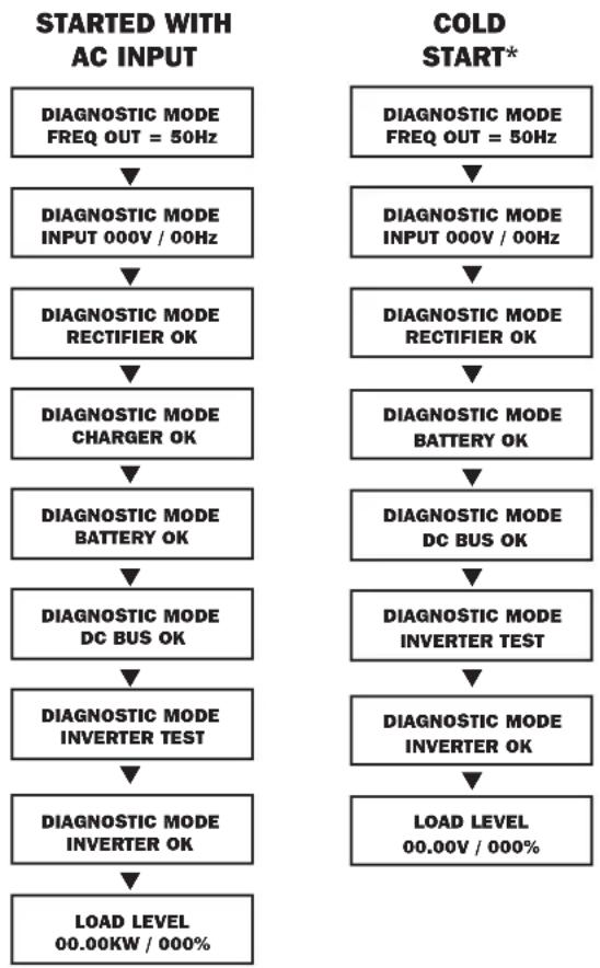
flowchart
graph TD
    A["DIAGNOSTIC MODE FREQ OUT = 50Hz"] --> B["DIAGNOSTIC MODE INPUT 000V / 00Hz"]
    B --> C["DIAGNOSTIC MODE RECTIFIER OK"]
    C --> D["DIAGNOSTIC MODE CHARGER OK"]
    D --> E["DIAGNOSTIC MODE BATTERY OK"]
    E --> F["DIAGNOSTIC MODE DC BUS OK"]
    F --> G["DIAGNOSTIC MODE INVERTER TEST"]
    G --> H["DIAGNOSTIC MODE INVERTER OK"]
    H --> I["LOAD LEVEL 00.00V / 000%"]

    J["COLD START*"] --> K["DIAGNOSTIC MODE FREQ OUT = 50Hz"]
    K --> L["DIAGNOSTIC MODE INPUT 000V / 00Hz"]
    L --> M["DIAGNOSTIC MODE RECTIFIER OK"]
    M --> N["DIAGNOSTIC MODE BATTERY OK"]
    N --> O["DIAGNOSTIC MODE DC BUS OK"]
    O --> P["DIAGNOSTIC MODE INVERTER TEST"]
    P --> Q["DIAGNOSTIC MODE INVERTER OK"]
    Q --> R["LOAD LEVEL 00.00V / 000%"]
*Note: If the UPS is cold started, its BATTERY LED will be illuminated.
Failed Self-Test
If a problem is detected during the self-test, the LCD will display a error message. If your UPS displays any of the following messages in its LCD, call Tripp Lite Technical Support at 773.869.1234 for service.
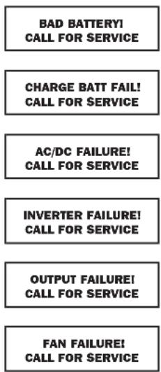
flowchart
graph TD
    A["BAD BATTERY! CALL FOR SERVICE"] --> B["CHARGE BATT FAIL! CALL FOR SERVICE"]
    B --> C["AC/DC FAILURE! CALL FOR SERVICE"]
    C --> D["INVERTER FAILURE! CALL FOR SERVICE"]
    D --> E["OUTPUT FAILURE! CALL FOR SERVICE"]
    E --> F["FAN FAILURE! CALL FOR SERVICE"]
Operation
Normal Operation
During normal operation, the first line of your LCD screen shows which operating mode your UPS is in: On-Line, Economy, On-Battery, or Bypass.
On-line mode: The UPS provides AC power while utility power is available and switches to On Battery mode instantly (zero transfer time) if AC power is interrupted.
Economy mode: The UPS provides AC power at high efficiency while utility power is within +/- 10% rated AC input voltage and switches to On-Battery mode (zero transfer time) if AC power is interrupted.
Note: Economy mode is only supported in single UPS power module 8kVA and 10kVA configurations.
Industrial mode: If the UPS detects an output voltage fluctuation more than 5 ms, the UPS will transfer to Bypass mode, returning to On-line mode when the output is back to normal.
On-battery mode: The UPS provides AC power from battery backup so long as battery power lasts. It switches back to On-line or Economy mode if utility power is available and shuts down if it runs out of battery power.
Bypass mode: The UPS provides AC power while utility power is available. The UPS shuts down if AC power is interrupted.
Parallel mode: The UPS can provide redundancy up to 10K or power up to 20K. Refer to your Paralleling Kit manual for more information.
The second line of the LCD screen shows basic power conditions. Push the SCROLL buttons to browse through these basic power conditions in the sequence shown below.
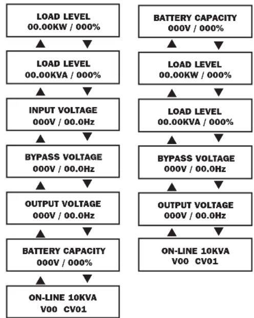
flowchart
graph TD
    A["LOAD LEVEL 00.00KW / 000%"] --> B["LOAD LEVEL 00.00KVA / 000%"]
    B --> C["INPUT VOLTAGE 000V / 00.0Hz"]
    C --> D["BYPASS VOLTAGE 000V / 00.0Hz"]
    D --> E["OUTPUT VOLTAGE 000V / 00.0Hz"]
    E --> F["BATTERY CAPACITY 000V / 000%"]
    F --> G["ON-LINE 10KVA V00 CV01"]

    H["BATTERY CAPACITY 000V / 000%"] --> I["LOAD LEVEL 00.00KW / 000%"]
    I --> J["LOAD LEVEL 00.00KVA / 000%"]
    J --> K["BYPASS VOLTAGE 000V / 00.0Hz"]
    K --> L["OUTPUT VOLTAGE 000V / 00.0Hz"]
    L --> M["ON-LINE 10KVA V00 CV01"]
UPS Setup Menu
Press the UP↑ and DOWN↓ buttons simultaneously for 3 seconds until the SETUP MENU screen appears as seen below:

Press the UP↑ button to enter Set Up Mode.
To enter Set Up Mode, you will be required to enter a password.

Numbers increase or decrease by 1 when pressing the UP↑ and DOWN↓ buttons (0-9). Scroll to select the first number, then press the ON button. This saves the first number and moves on to the next in the sequence. The password range is 0000-9999 and should be changed by the administrator. The DEFAULT password is 1234.
Operation
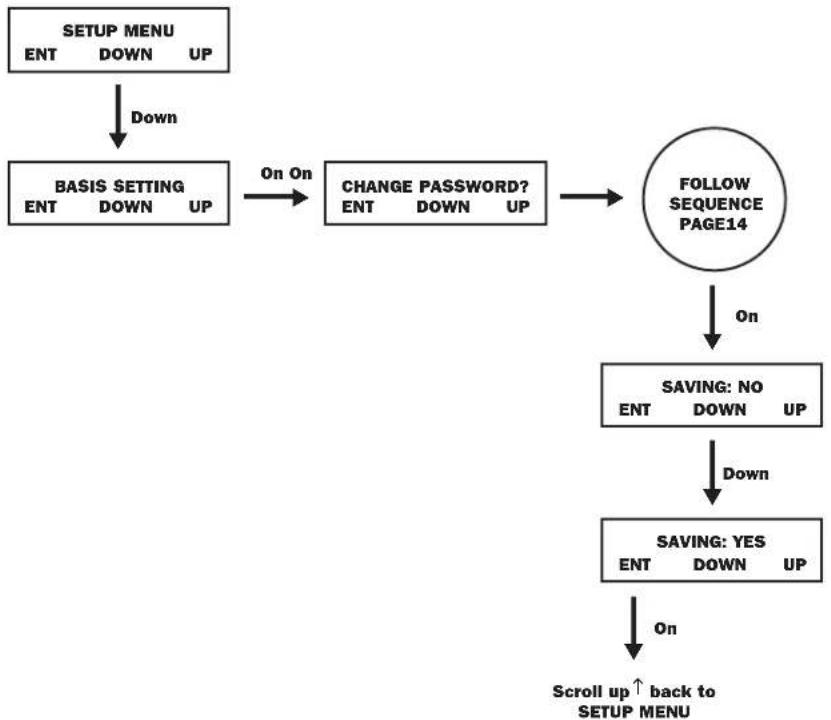
Changing the Password
To change the password, scroll DOWN↓ from the SETUP MENU screen to the BASIS SETTING screen. From here, press ON for the CHANGE PASSWORD screen. From this screen press ON and follow the previously described actions to set your password. When set, press ON to move to the SAVING screen. Scroll DOWN↓ to the SAVING:YES screen and press ON to save. Scrolling back UP↑ will return you to the SETUP MENU.
flowchart
graph TD
    A["SETUP MENU\nENT DOWN UP"] -->|Down| B["BASIS SETTING\nENT DOWN UP"]
    B -->|On On| C["CHANGE PASSWORD?\nENT DOWN UP"]
    C --> D["FOLLOW SEQUENCE PAGE14"]
    D -->|On| E["SAVING: NO\nENT DOWN UP"]
    E -->|Down| F["SAVING: YES\nENT DOWN UP"]
    F -->|On| G["Scroll up ↑ back to SETUP MENU"]
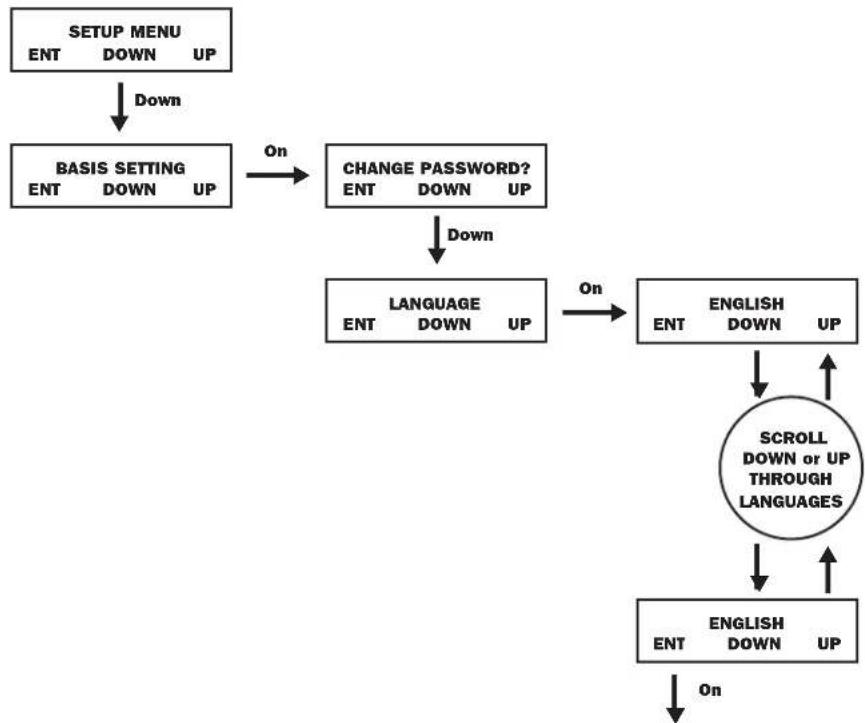
Selecting Screen Language
To select a screen language, scroll DOWN↓ to the BASIS SETTING screen. Press ON to get to the CHANGE PASSWORD screen and DOWN↓ to get to the LANGUAGE screen. From here, press ON. You can then scroll DOWN↓ or UP↑ through languages until you find your desired language. Press ON to save your selection.
flowchart
graph TD
    A["SETUP MENU\nENT DOWN UP"] -->|Down| B["BASIS SETTING\nENT DOWN UP"]
    B -->|On| C["CHANGE PASSWORD?\nENT DOWN UP"]
    C -->|Down| D["LANGUAGE\nENT DOWN UP"]
    D -->|On| E["ENGLISH\nENT DOWN UP"]
    E --> F["SCROLL\nDOWN or UP\nTHROUGH LANGUAGES"]
    F --> G["ENGLISH\nENT DOWN UP"]
    G -->|On| H["End"]
Operation
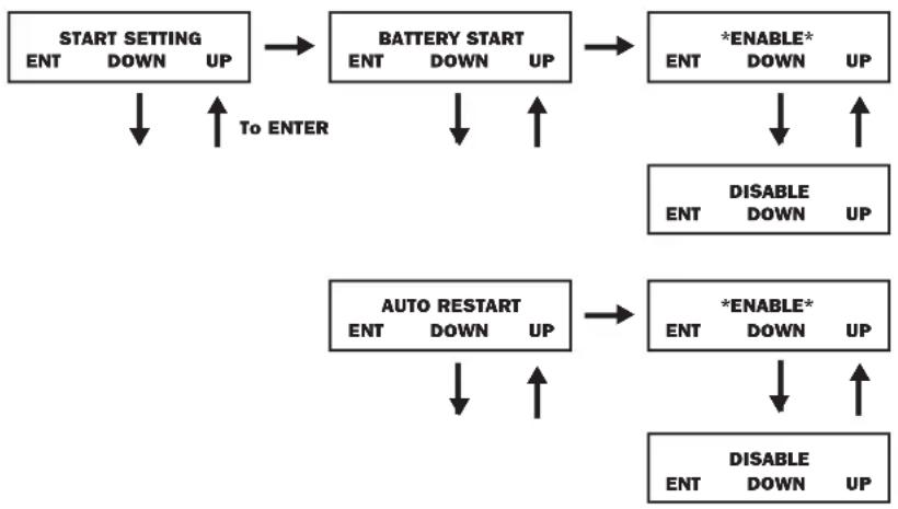
Start Settings
The UPS can start up through the battery without AC power. The DEFAULT is ENABLE. When the UPS switches to battery it can AUTO RESTART to work in an On-Line Mode when AC power is restored. DEFAULT is ENABLE.
From the SETUP MENU screen, scroll DOWN↓ to the START SETTING screen. From here, press the ON button for the BATTERY START screen. From this screen, pressing ON moves you to a ENABLE screen. Pressing ON will enable, while scrolling DOWN↓ takes you to a DISABLE screen. From here, press ON to DISABLE this function.
From the BATTERY START screen, pressing DOWN↓ will take you to an AUTO RESTART screen. Pressing ON takes you to an ENABLE screen; press ON to ENABLE. Pressing DOWN↓ takes you to a DISBALE screen. Press ON to DISBALE this function.
flowchart
graph TD
    A["START SETTING"] --> B["BATTERY START"]
    B --> C["*ENABLE*"]
    C --> D["DISABLE"]
    D --> E["AUTO RESTART"]
    E --> F["*ENABLE*"]
    F --> G["DISABLE"]
    G --> H["To ENTER"]
    H --> A
    style A fill:#f9f,stroke:#333
    style B fill:#f9f,stroke:#333
    style C fill:#ccf,stroke:#333
    style D fill:#ccf,stroke:#333
    style E fill:#ccf,stroke:#333
    style F fill:#ccf,stroke:#333
    style G fill:#ccf,stroke:#333
    style H fill:#ccf,stroke:#333
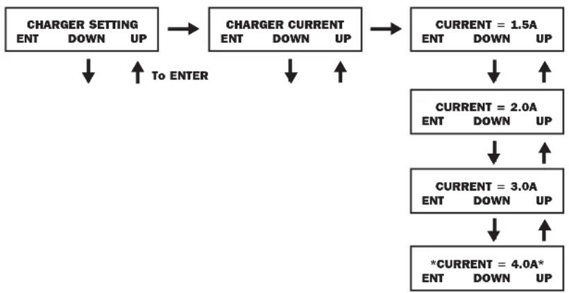
Charger Settings
From the SETUP MENU screen, scroll DOWN↓ until you reach the CHARGER SETTING screen. From here, press ON to get to the CHARGER CURRENT screen. Press ON again. From here, you can scroll DOWN↓ or UP↑ to select current values between 1.5 and 4.0A. Press ON to save your desired value.
flowchart
graph TD
    A["CHARGER SETTING"] --> B["CHARGER CURRENT"]
    B --> C["CURRENT = 1.5A"]
    C --> D["CURRENT = 2.0A"]
    D --> E["CURRENT = 3.0A"]
    E --> F["*CURRENT = 4.0A*"]
    A -->|To ENTER| B
    B -->|To ENTER| C
    C -->|To ENTER| D
    D -->|To ENTER| E
    E -->|To ENTER| F
    F -->|To ENTER| G["ENT DOWN UP"]
    G --> H["ENT DOWN UP"]
    H --> I["ENT DOWN UP"]
    I --> J["ENT DOWN UP"]
Operation
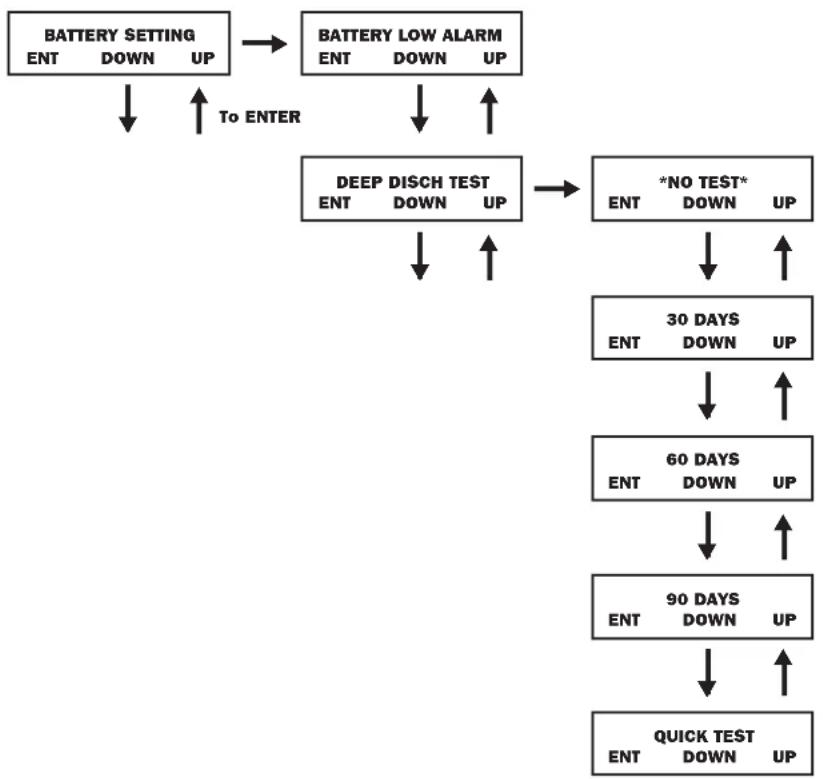
Battery Settings
Deep Discharge Test: Sets the time period for deep discharge tests. From the SETUP MENU screen, scroll DOWN↓ until you reach the BATTERY SETTING screen. Press ON for the BATTERY LOW ALARM screen and scroll DOWN↓ until you reach the DEEP DISCH TEST screen. Here, press ON. Now you can scroll DOWN↓ or UP↑ between NO TEST, 30, 60, 90 days and QUICK TEST. When you reach your desired time length, press ON to save. The DEFAULT is NO TEST.
flowchart
graph TD
    A["BATTERY SETTING"] --> B["BATTERY LOW ALARM"]
    B --> C["DEEP DISCH TEST"]
    C --> D["*NO TEST*"]
    D --> E["30 DAYS"]
    E --> F["60 DAYS"]
    F --> G["90 DAYS"]
    G --> H["QUICK TEST"]
    H --> I["Next Step"]
    style A fill:#f9f,stroke:#333
    style B fill:#f9f,stroke:#333
    style C fill:#ccf,stroke:#333
    style D fill:#ccf,stroke:#333
    style E fill:#ccf,stroke:#333
    style F fill:#ccf,stroke:#333
    style G fill:#ccf,stroke:#333
    style H fill:#ccf,stroke:#333
    style I fill:#ccf,stroke:#333
Operation
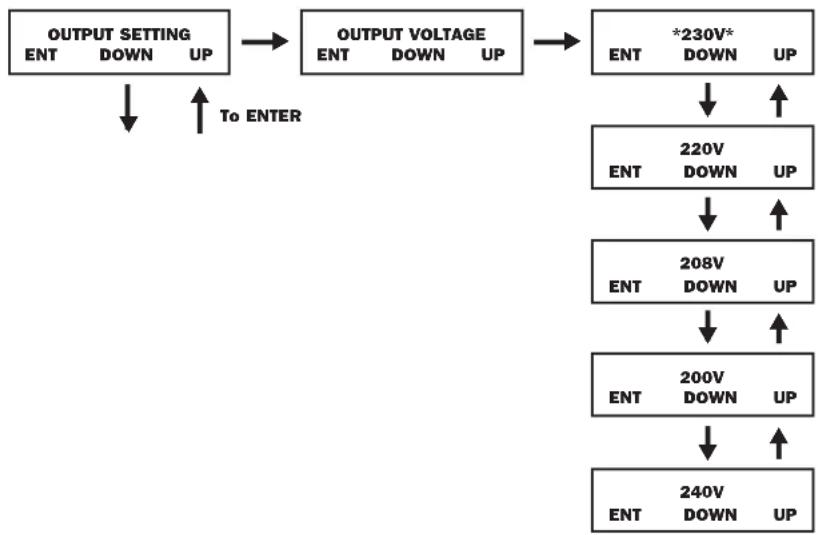
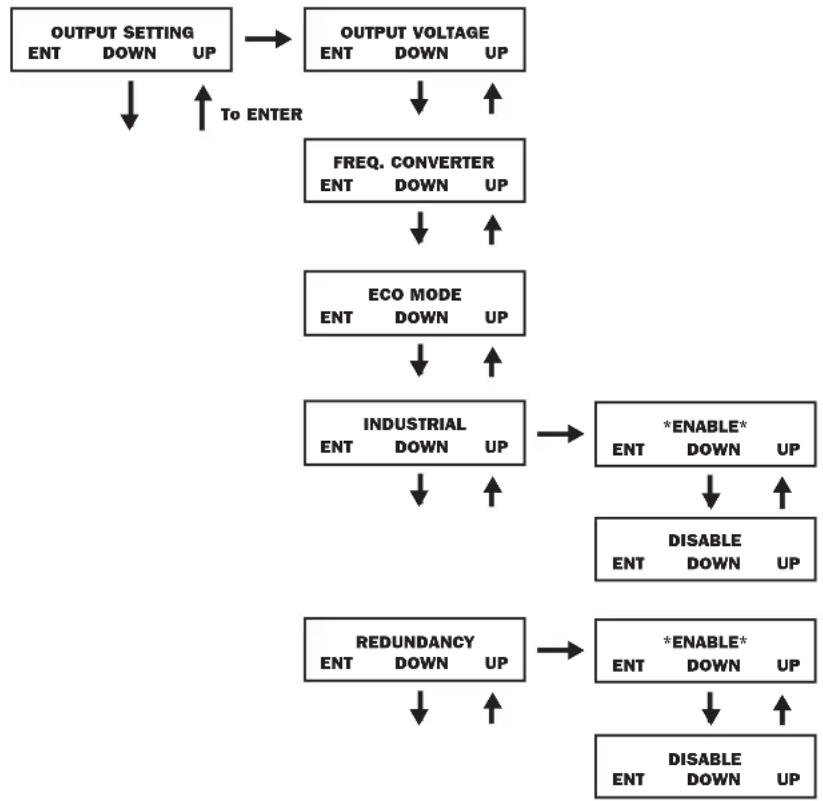
Output Settings
Note: Any Output Setting changes require a UPS power cycle.
Output Voltage: Sets the UPS output voltage rating. From the SETUP MENU screen, scroll DOWN↓ until you reach the OUTPUT SETTING screen. Press ON to reach an OUTPUT VOLTAGE screen and ON again. You can now scroll DOWN↓ or UP↑ between 5 voltage values: 200/208/220/230/240V. Press ON to save your desired voltage.
DEFAULT: 208V
flowchart
graph TD
    A["OUTPUT SETTING"] --> B["OUTPUT VOLTAGE"]
    B --> C["*230V*"]
    C --> D["220V DOWN UP"]
    D --> E["208V DOWN UP"]
    E --> F["200V DOWN UP"]
    F --> G["240V DOWN UP"]
    G --> H["To ENTER"]
    H --> A
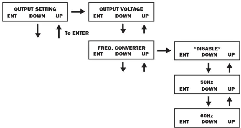
Frequency Converter: Sets the Frequency Converter Mode. From the SETUP MENU screen, scroll DOWN↓ until you reach the OUTPUT SETTING screen. Press ENTER for the OUTPUT VOLTAGE screen and DOWN↓ to access the FREQ CONVERTER screen. Here, press ON. Now you can scroll DOWN↓ or UP↑ between DISABLE, 50 and 60 Hz. Press ON to save your selection. When on DISABLE, the UPS will automatically detect input frequency and select 50 or 60 Hz accordingly. The DEFAULT selection is DISABLE.
flowchart
graph TD
    A["OUTPUT SETTING"] --> B["OUTPUT VOLTAGE"]
    B --> C["FREQ. CONVERTER"]
    C --> D["*DISABLE*"]
    D --> E["50Hz UP"]
    E --> F["60Hz UP"]
    A --> G["ENT DOWN UP"]
    B --> H["ENT DOWN UP"]
    C --> I["ENT DOWN UP"]
    D --> J["ENT DOWN UP"]
    style A fill:#f9f,stroke:#333
    style B fill:#f9f,stroke:#333
    style C fill:#f9f,stroke:#333
    style D fill:#ccf,stroke:#333
    style E fill:#ccf,stroke:#333
    style F fill:#ccf,stroke:#333
    style G fill:#fff,stroke:#333
    style H fill:#fff,stroke:#333
    style I fill:#fff,stroke:#333
    style J fill:#fff,stroke:#333
Operation
Output Settings
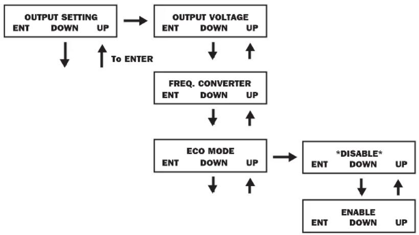
ECO Mode: Sets the UPS to operate in energy saving Economy Mode. When input voltage is in a + or - range of 10% of the overall voltage rating, the UPS will transfer into an Economy Mode to improve the efficiency of the UPS. From the SETUP MENU screen, scroll DOWN↓ until you reach the OUTPUT SETTING screen. From here, press ON for the OUTPUT VOLTAGE screen, and DOWN↓ through the FREQ CONVERTER screen until you reach the ECO MODE screen. From here, press ON and now you can scroll DOWN↓ or UP↑ between DISABLE and ENABLE. Press ON to save your selection. The DEFAULT setting is DISABLE.
flowchart
graph TD
    A["OUTPUT SETTING"] --> B["OUTPUT VOLTAGE"]
    B --> C["FREQ. CONVERTER"]
    C --> D["ECO MODE"]
    D --> E["*DISABLE*"]
    E --> F["ENABLE DOWN UP"]
    D --> G["ENT DOWN UP"]
    G --> H["To ENTER"]
    H --> I["OUTPUT SETTING"]
    I --> J["OUTPUT VOLTAGE"]
    J --> K["FREQ. CONVERTER"]
    K --> L["ECO MODE"]
    L --> M["*DISABLE*"]
    M --> N["ENABLE DOWN UP"]
    N --> O["To ENTER"]
    O --> P["OUTPUT SETTING"]
Industrial: Sets the UPS voltage protection. If enabled, and receiving AC power with input voltage and frequency within a normal range the UPS will work in an On-Line mode. If the UPS detects an output voltage fluctuation more than 5 ms, the UPS will transfer to Bypass Mode, returning to On-Line Mode when the output is back to normal. From the STARTUP MENU screen, scroll DOWN↓ until you reach the OUTPUT SETTING screen. From here, press ON to reach the OUTPUT VOLTAGE screen, and DOWN↓ until you reach the INDUSTRIAL screen. From here, press ON and you can now scroll DOWN↓ or UP↑ for ENABLE or DISABLE. Press ON to save your selection. The DEFAULT is DISABLE. Scrolling DOWN from the INDUSTRIAL screen will take you to a REDUNDANCY screen. From here, press ON and you can now scroll DOWN or UP for ENABLE or DISABLE. The DEFAULT setting is DISABLE.
flowchart
graph TD
    A["OUTPUT SETTING"] --> B["OUTPUT VOLTAGE"]
    B --> C["FREQ. CONVERTER"]
    C --> D["ECO MODE"]
    D --> E["INDUSTRIAL"]
    E --> F["*ENABLE*"]
    F --> G["DISABLE"]
    G --> H["REDUNDANCY"]
    H --> I["*ENABLE*"]
    I --> J["DISABLE DOWN UP"]
    A --> K["To ENTER"]
    K --> L["OUTPUT SETTING"]
    L --> M["OUTPUT VOLTAGE"]
    M --> N["FREQ. CONVERTER"]
    N --> O["ECO MODE"]
    O --> P["INDUSTRIAL"]
    P --> Q["*ENABLE*"]
    Q --> R["DISABLE DOWN UP"]
    P --> S["REDUNDANCY"]
    S --> T["*ENABLE*"]
    T --> U["DISABLE DOWN UP"]
Operation
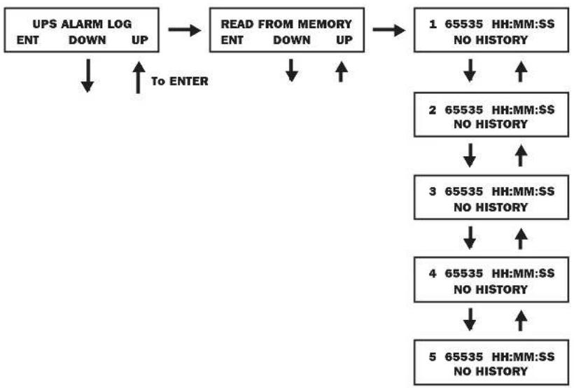
UPS Alarm Log
flowchart
graph TD
    A["UPS ALARM LOG"] --> B["READ FROM MEMORY"]
    B --> C["1 65535 HH:MM:SS\nNO HISTORY"]
    B --> D["2 65535 HH:MM:SS\nNO HISTORY"]
    D --> E["3 65535 HH:MM:SS\nNO HISTORY"]
    E --> F["4 65535 HH:MM:SS\nNO HISTORY"]
    F --> G["5 65535 HH:MM:SS\nNO HISTORY"]
    A --> H["To ENTER"]
    H --> I["UP"]
    I --> J["DOWN"]
    J --> K["ENT"]
    K --> L["UP"]
    L --> M["Down"]
    M --> N["UP"]
    N --> O["Down"]
    O --> P["UP"]
Read From Memory: records the last 5 fault events from the EEPROM. See the Fail Event List below:
| Fail Event List | ||
| DC BUS FAIL CHARGER BATTERY FAIL OUTPUT FUSE | FAIL | |
| SHORT CIRCUIT BYPASS SCR SHORT FAIL DC BUS OVP FAIL | ||
| INVERTER FAIL INPUT SCR SHORT FAIL INPUT HVP RELAY SHORT FAIL | ||
| OVER TEMPERATURE DERATE SHUTDOWN INPUT HVP RELAY OPEN FAIL | ||
| OUTPUT SCR FAIL ENERGY SAVING NTC OPEN FAIL | ||
| OVERLOAD OUTPUT HAS VOLTAGE LOW TEMP FAIL | ||
| FAN FAIL INPUT FUSE FAIL | ||
From the SETUP MENU screen, scroll DOWN↓ until you reach the UPS ALARM LOG screen. Press ON to enter the READ FROM MEMORY screen and ON again. Here, you can scroll DOWN↓ or UP↑ to read the last 5 fault events. Press ON to exit this menu.
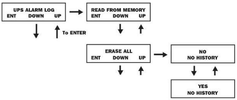
Erase All: Clears the Fault Event Log. From the STARTUP MENU, scroll DOWN↓ until you reach the UPS ALARM LOG screen. From here, press ON to reach the READ FROM MEMORY screen and press DOWN↓ for the ERASE ALL screen. From here you can scroll DOWN↓ or UP↑ between Yes and No. Press ON to save your selection. You will now be presented with a SURE? screen. Press ON to save or scroll for more options.
flowchart
graph TD
    A["UPS ALARM LOG\nENT DOWN UP"] --> B["READ FROM MEMORY\nENT DOWN UP"]
    B --> C["ERASE ALL\nENT DOWN UP"]
    C --> D["NO\nNO HISTORY"]
    D --> E["YES\nNO HISTORY"]
    F["To ENTER"] --> A
    G["To ENTER"] --> B
    H["To ENTER"] --> C
    I["To ENTER"] --> D
    J["To ENTER"] --> E
Operation
Self Diagnosis Information
When starting with AC power, you will see the following display sequence:
flowchart
graph TD
    A["DIAGNOSTIC MODE FREQ OUT = 50Hz"] --> B["DIAGNOSTIC MODE INPUT 000V / 00Hz"]
    B --> C["DIAGNOSTIC MODE RECTIFIER OK"]
    C --> D["DIAGNOSTIC MODE CHARGER OK"]
    D --> E["DIAGNOSTIC MODE BATTERY OK"]
    E --> F["DIAGNOSTIC MODE DC BUS OK"]
    F --> G["DIAGNOSTIC MODE INVERTER TEST"]
    G --> H["DIAGNOSTIC MODE INVERTER OK"]
    H --> I["LOAD LEVEL 00.00KW / 000%"]
When starting on battery power, you will see the following display sequence:
flowchart
graph TD
    A["DIAGNOSTIC MODE FREQ OUT = 50Hz"] --> B["DIAGNOSTIC MODE INPUT 000V / 00Hz"]
    B --> C["DIAGNOSTIC MODE RECTIFIER OK"]
    C --> D["DIAGNOSTIC MODE BATTERY OK"]
    D --> E["DIAGNOSTIC MODE DC BUS OK"]
    E --> F["DIAGNOSTIC MODE INVERTER TEST"]
    F --> G["DIAGNOSTIC MODE INVERTER OK"]
    G --> H["LOAD LEVEL 00.00V / 000%"]
Operation
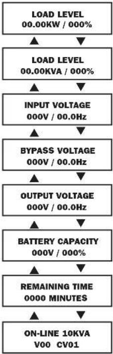
Display Information-Online Mode
When operating in Online Mode with AC power present, you will see the following display sequence:
flowchart
graph TD
    A["LOAD LEVEL 00.00KW / 000%"] --> B["LOAD LEVEL 00.00KVA / 000%"]
    B --> C["INPUT VOLTAGE 000V / 00.0Hz"]
    C --> D["BYPASS VOLTAGE 000V / 00.0Hz"]
    D --> E["OUTPUT VOLTAGE 000V / 00.0Hz"]
    E --> F["BATTERY CAPACITY 000V / 000%"]
    F --> G["REMAINING TIME 0000 MINUTES"]
    G --> H["ON-LINE 10KVA V00 CV01"]
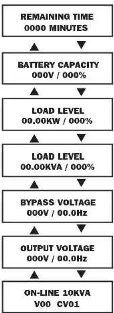
When operating in Online Mode under battery power, you will see the following display sequence:
flowchart
graph TD
    A["REMAINING TIME 0000 MINUTES"] --> B["BATTERY CAPACITY 000V / 000%"]
    B --> C["LOAD LEVEL 00.00KW / 000%"]
    C --> D["LOAD LEVEL 00.00KVA / 000%"]
    D --> E["BYPASS VOLTAGE 000V / 00.0Hz"]
    E --> F["OUTPUT VOLTAGE 000V / 00.0Hz"]
    F --> G["ON-LINE 10KVA V00 CV01"]
Operation
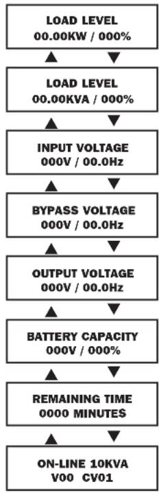
Display Information-Bypass Mode
When operating in Bypass Mode, you will see the following display sequence:
flowchart
graph TD
    A["LOAD LEVEL 00.00KW / 000%"] --> B["LOAD LEVEL 00.00KVA / 000%"]
    B --> C["INPUT VOLTAGE 000V / 00.0Hz"]
    C --> D["BYPASS VOLTAGE 000V / 00.0Hz"]
    D --> E["OUTPUT VOLTAGE 000V / 00.0Hz"]
    E --> F["BATTERY CAPACITY 000V / 000%"]
    F --> G["REMAINING TIME 0000 MINUTES"]
    G --> H["ON-LINE 10KVA V00 CV01"]
UPS Fault Shutdown Messages
| CONDITION LCD MESSAGE | |
| +BUS >450V + DC BUS HIGH SHUTDOWN | |
| Load <100%: +BUS < 320VLoad >100%: +BUS <290V | + DC BUS LOW SHUTDOWN |
| -BUS >450V - DC BUS HIGH SHUTDOWN | |
| Load <100%: -BUS <320VLoad >100%: -BUS <290V | - DC BUS LOW SHUTDOWN |
| BUS Voltage Over 500 BUS OVP FAIL SHUTDOWN | |
| Output Short OUTPUT SHORT SHUTDOWN | |
| UPS Over Temperature OVER TEMPERATURE SHUTDOWN | |
| Output SCR Open Failure OUTPUT SCR FAIL SHUTDOWN | |
| Output Overload OVERLOAD SHUTDOWN | |
| Bypass SCR Short BYPASS SCR FAIL SHUTDOWN | |
| Input SCR Rectifier Failure RECTIFIER FAIL SHUTDOWN | |
| Inverter Output Voltage Failure INVERTER SHUTDOWN | |
| Input Fuse Open I / P FUSE BROKEN SHUTDOWN | |
| Output Fuse Open O / P FUSE BROKEN SHUTDOWN | |
| Parallel ID Lost PARALLEL FAULT SHUTDOWN |
Operation
On-Battery Alarm
When in the On-Battery mode, the UPS power module will beep to inform you that it is using battery power to support connected equipment. If its connected batteries are at more than half capacity, it will beep every two seconds. If its connected batteries are below half capacity, it will beep twice per second. If its connected batteries are nearly depleted, the UPS power module will beep continuously.
To silence the On Battery Alarm, press the "ON/MUTE" button.
Overload Messages
When the UPS detects an output overload, its LCD will switch to the following display:
$$ \begin{array}{c} \text {OVERLOAD!} \ \text {LOAD = XXX\% X.XXKW} \end{array} $$
The UPS will then begin a countdown. If the UPS is still overloaded at the end of the countdown, the UPS will automatically go to Bypass Mode to protect its inverter. The duration of the countdown varies with the severity of the overload, as follows:
| Overload Condition Countdown Duration | |
| 106% - 125% | 1 minute |
| 126% - 150% | 30 seconds |
| >150% | Immediate |
Bypass Messages
While in Bypass Mode, the UPS monitors its input voltage and passes that input power along to connected equipment. The UPS will not provide battery backup in Bypass Mode.
If the output voltage deviates from an acceptable range (between 15% higher and 20% lower than nominal), the UPS displays the condition on its LCD and stops supplying output power to its load. If power levels return to an acceptable level, the UPS resumes supplying power to the load, and its LCD reports that output voltage was too high or too low at one time, but has returned to nominal.
| BYPASS VOLTAGE CONDITIONS | LCD DISPLAYMESSAGES |
| >15% Higher Than Nominal | BYPS OUT OF VOLT XXXV / XX.X HZ |
| >20% Lower Than Nominal | BYPS OUT OF VOLT XXXV / XX.X HZ |
Operation
Shutdown Messages
Your UPS will shut down and the LCD will display a message if it detects one of the following conditions.
Note: During all these conditions, the "Input," "Output" and "Bypass" LEDs will illuminate.
| SHUTDOWN CONDITIONS | LCD DISPLAYMESSAGES |
| ExtendedOverload | SHUT DOWNOVERLOAD XXX% |
| Output ShortCircuit | SHUT DOWNO/P SHORT CIRCUIT |
| Remote ShutdownCommand (Via DB9) | SHUT DOWNREMOTE COMMAND |
| Remote ShutdownCommand (Via EPO) | SHUT DOWNEMERGENCY STOP! |
| InternalFaults | SHUT DOWN+ DC BUS HIGH |
| SHUT DOWN+ DC BUS LOW | |
| SHUT DOWN- DC BUS HIGH | |
| SHUT DOWN- DC BUS LOW | |
| SHUT DOWNOVERTEMPERATURE |
Storage and Service
Storage
Before storing your UPS, turn it completely OFF. If you store your UPS for an extended period of time, recharge the UPS batteries for 4 to 6 hours once every three months. Note: after you connect the UPS to utility power, it will automatically begin charging its batteries. If you leave your UPS batteries discharged for an extended period of time, they will suffer a permanent loss of capacity.
Service
Your SmartOnline UPS is covered by the 2-year limited warranty period described below. A variety of Extended Warranty and On-Site Service Programs are also available from Tripp Lite. For more information on service, visit tripplite.com/support. Before returning your UPS for service, follow these steps:
- Review the installation and operation procedures in this manual to insure that the service problem does not originate from a misreading of the instructions.
- If the problem continues, do not contact or return the UPS to the dealer. Instead, visit tripplite.com/support
- If the problem requires service, visit tripplite.com/support and click the Product Returns link. From here you can request a Returned Material Authorization (RMA) number, which is required for service. This simple on-line form will ask for your unit's model and serial numbers, along with other general purchaser information. The RMA number, along with shipping instructions will be emailed to you. Any damages (direct, indirect, special or consequential) to the UPS incurred during shipment to Tripp Lite or an authorized Tripp Lite service center is not covered under warranty. UPS systems shipped to Tripp Lite or an authorized Tripp Lite service center must have transportation charges prepaid. Mark the RMA number on the outside of the package. If the UPS system is within the 2-year warranty period, enclose a copy of your sales receipt. Return the UPS for service using an insured carrier to the address given to you when you request the RMA.
Warranty and Product Registration
2-Year Limited Warranty
TRIPP LITE warrants its products including batteries to be free from defects in materials and workmanship for a period of two years from the date of initial purchase. After 90 days from the date of purchase, TRIPP LITE's obligation under this warranty is limited to replacing parts on such defective products. To obtain service under this warranty, you must call TRIPP LITE or an authorized TRIPP LITE service center. Products must be returned to TRIPP LITE or an authorized TRIPP LITE service center with transportation charges prepaid and must be accompanied by a brief description of the problem encountered and proof of date and place of purchase. This warranty does not apply to equipment which has been damaged by accident, negligence or misapplication or has been altered or modified in any way. This warranty applies only to the original purchaser who must have properly registered the product within 10 days of purchase.
The warranties of all TRIPP LITE surge suppressors are null and void if they have been connected to the output of any UPS system. The warranties of all TRIPP LITE UPS Systems are null and void if a surge suppressor has been connected to its output receptacles.
EXCEPT AS PROVIDED HEREIN, TRIPP LITE MAKES NO WARRANTIES, EXPRESS OR IMPLIED, INCLUDING WARRANTIES OF MERCHANTABILITY AND FITNESS FOR A PARTICULAR PURPOSE. Some states do not permit limitation or exclusion of implied warranties; therefore, the aforesaid limitation(s) or exclusion(s) may not apply to the purchaser.
EXCEPT AS PROVIDED ABOVE, IN NO EVENT WILL TRIPP LITE BE LIABLE FOR DIRECT, INDIRECT, SPECIAL, INCIDENTAL OR CONSEQUENTIAL DAMAGES ARISING OUT OF THE USE OF THIS PRODUCT, EVEN IF ADVISED OF THE POSSIBILITY OF SUCH DAMAGE. Specifically, TRIPP LITE is not liable for any costs, such as lost profits or revenue, loss of equipment, loss of use of equipment, loss of software, loss of data, costs of substitutes, claims by third parties, or otherwise.
PRODUCT REGISTRATION
Visit www.tripplite.com/warranty today to register your new Tripp Lite product. You'll be automatically entered into a drawing for a chance to win a FREE Tripp Lite product!* * No purchase necessary. Void where prohibited. Some restrictions apply. See website for details.
FCC Part 68 Notice (United States Only)
If your Modem/Fax Protection causes harm to the telephone network, the telephone company may temporarily discontinue your service. If possible, they will notify you in advance. If advance notice isn't practical, you will be notified as soon as possible. You will be advised of your right to file a complaint with the FCC. Your telephone company may make changes in its facilities, equipment, operations or procedures that could affect the proper operation of your equipment. If it does, you will be given advance notice to give you an opportunity to maintain uninterrupted service. If you experience trouble with this equipment's Modem/Fax Protection, please call Tripp Lite Technical Support at (773) 869-1234 for repair/warranty information. The telephone company may ask you to disconnect this equipment from the network until the problem has been corrected or you are sure the equipment is not malfunctioning. There are no repairs that can be made by the customer to the Modem/Fax Protection. This equipment may not be used on coin service provided by the telephone company. Connection to party lines is subject to state tariffs. (Contact your state public utility commission or corporation commission for information.)
Regulatory Compliance Identification Numbers
For the purpose of regulatory compliance certifications and identification, your Tripp Lite product has been assigned a unique series number. The series number can be found on the product nameplate label, along with all required approval markings and information. When requesting compliance information for this product, always refer to the series number. The series number should not be confused with the marking name or model number of the product.
WEEE Compliance Information for Tripp Lite Customers and Recyclers (European Union)

Under the Waste Electrical and Electronic Equipment (WEEE) Directive and implementing regulations, when customers buy new electrical and electronic equipment from Tripp Lite they are entitled to:
- Send old equipment for recycling on a one-for-one, like-for-like basis (this varies depending on the country)
- Send the new equipment back for recycling when this ultimately becomes waste
Tripp Lite has a policy of continuous improvement. Specifications are subject to change without notice. Photos and illustrations may differ slightly from actual products.

text_image
TRIPP·LITE
Manufacturing Excellence.
1111 W. 35th Street, Chicago, IL 60609 USA • tripplite.com/support
text_image
E 0 3 D F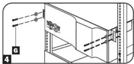
text_image
TRIPFUTE G 4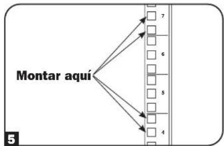
flowchart
graph TD
    A["Montar aquí"] --> B["7"]
    A --> C["6"]
    A --> D["5"]
    A --> E["4"]
flowchart
graph TD
    A["UP"] --> B["BATTERY"]
    B --> C["AC/DC"]
    C --> D["BYPRESS"]
    D --> E["DC/AC"]
    E --> F["G/P"]
    style A fill:#f9f,stroke:#333
    style B fill:#ccf,stroke:#333
    style C fill:#cfc,stroke:#333
    style D fill:#fcc,stroke:#333
    style E fill:#cff,stroke:#333
    style F fill:#ffc,stroke:#333
    subgraph Control Panel
        direction LR
        G["ON MUTE"] --> H["SETUP"]
        I["SETUP"] --> J["SETUP"]
        K["SETUP"] --> L["SETUP"]
        M["SETUP"] --> N["SETUP"]
        O["SETUP"] --> P["SETUP"]
        Q["SETUP"] --> R["SETUP"]
        S["SETUP"] --> T["SETUP"]
        U["SETUP"] --> V["SETUP"]
        W["SETUP"] --> X["SETUP"]
        Y["SETUP"] --> Z["SETUP"]
        AA["SETUP"] --> AB["SETUP"]
        AC["SETUP"] --> AD["SETUP"]
        AE["SETUP"] --> AF["SETUP"]
        AG["SETUP"] --> AH["SETUP"]
        AI["SETUP"] --> AJ["SETUP"]
        AK["SETUP"] --> AL["SETUP"]
        AM["SETUP"] --> AN["SETUP"]
        AO["SETUP"] --> AP["SETUP"]
        AQ["SETUP"] --> AR["SETUP"]
        AS["SETUP"] --> AT["SETUP"]
        AU["SETUP"] --> AV["SETUP"]
        AW["SETUP"] --> AX["SETUP"]
        AY["12"] --> Z
    end
text_image
Diagram of an electronic device with labeled components including fan, buttons, and control panel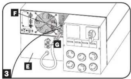
text_image
F G E 3
flowchart
graph TD
    A["UP"] --> B["BATTERY"]
    B --> C["AC/DC"]
    C --> D["DC/DC"]
    D --> E["GP"]
    F["H"] --> G["J"]
    G --> H["ON"]
    G --> I["↓"]
    G --> J["↑"]
    G --> K["OFF"]
    L["I"] --> M["NOTE"]
    N["J"] --> O["SETUP"]
    P["K"] --> Q["SETUP"]
text_image
L M N O 4bConexión
natural_image
Diagram of a multi-pin electrical plug with multiple socket designs (no text or labels)Conexión opcional
natural_image
Diagram of an electronic device with a power outlet connected to a fan and ports (no text or symbols visible)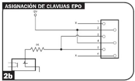
natural_image
Technical line drawing of a cabinet or enclosure with circular buttons and a control panel, enclosed in a structural frame (no text or symbols)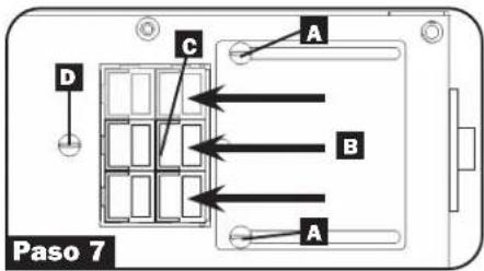
text_image
D C A B A Paso 7text_image
WARNING! RISK OF ELECTRICAL SHOCK EVEN WITHOUT AC PRESENT CONTACTS MAY BE UBE BIG TOP OF UNIT FOR ADDITIONAL CAUTIONS AND WARNINGS.Contactos de la PDU desmontable

natural_image
Pure electrical circuit lines without any symbolsEspecificaciones
flowchart
graph TD
    A[" "] --> B[" "]
    B --> C[" "]
    C --> D[" "]
    D --> E[" "]
    style A fill:#fff,stroke:#000
    style B fill:#fff,stroke:#000
    style C fill:#fff,stroke:#000
    style D fill:#fff,stroke:#000
    style E fill:#fff,stroke:#000
flowchart
graph TD
    A["IPBYPASS"] --> B["AC/DC"]
    C["IPBYPASS"] --> D["AC/DC"]
    B --> E[" "]
    D --> F[" "]
flowchart
graph TD
    A[" "] --> B[" "]
    B --> C[" "]
    C --> D[" "]
    E[" "] --> F[" "]
    F --> G[" "]
    H[" "] --> I[" "]
    I --> J[" "]
    K[" "] --> L[" "]
    L --> M[" "]
    N[" "] --> O[" "]
    O --> P[" "]
    Q[" "] --> R[" "]
    R --> S[" "]
    T[" "] --> U[" "]
    U --> V[" "]
Funcionamiento
1111 W. 35th Street, Chicago, IL 60609 USA • tripplite.com/support
21-11-122 93-2897 RoVE
1111 W. 35th Street, Chicago, IL 60609 USA • tripplite.com/support
text_image
E 0 3 D F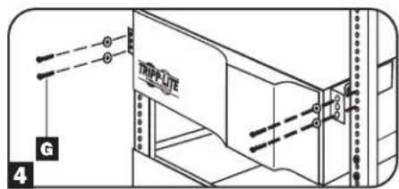
text_image
G 4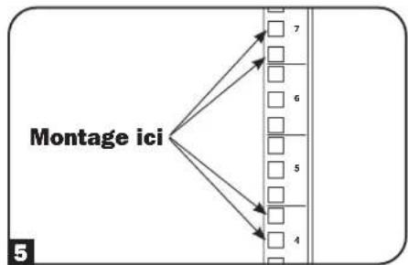
flowchart
graph TD
    A["Montage ici"] --> B["1"]
    A --> C["2"]
    A --> D["3"]
    A --> E["4"]
    A --> F["5"]
    A --> G["6"]
    A --> H["7"]
flowchart
graph TD
    A["Start"] --> B["Document with Icon"]
    B --> C["Arrow indicating rotation or feedback"]
Caractéristiques
text_image
Diagram of an electronic device with labeled components including fan, control panel, and buttons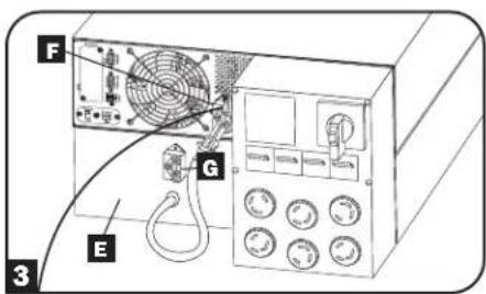
text_image
F G E 3
flowchart
graph TD
    A["BATTERY"] --> B["AC/DC"]
    B --> C["DC/AC"]
    C --> D["GTP"]
    E["ON"] --> F["SETUP"]
    G["OFF"] --> H["J"]
    I["H"] --> J["H"]
    style A fill:#fff,stroke:#000
    style B fill:#fff,stroke:#000
    style C fill:#fff,stroke:#000
    style D fill:#fff,stroke:#000
    style E fill:#fff,stroke:#000
    style F fill:#fff,stroke:#000
    style G fill:#fff,stroke:#000
    style H fill:#fff,stroke:#000
    style I fill:#fff,stroke:#000
    style J fill:#fff,stroke:#000
text_image
L M N O 4bRaccordement
natural_image
Diagram of a plug socket with six circular connectors, no text or symbols present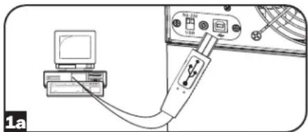
natural_image
Diagram showing connection between a computer and a device with a USB cable (no text or symbols visible)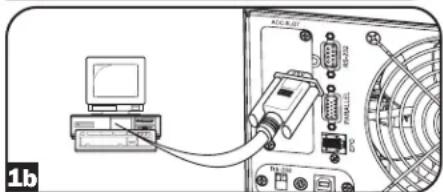
natural_image
Diagram showing connection between a computer and electronic device with ports and connectors (no readable text or symbols)Raccordement facultatif
natural_image
Diagram of an electronic device with a power outlet connected to a fan and ports (no text or symbols visible)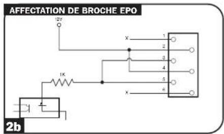
text_image
AFFECTATION DE BROCHE EPO 12V 1K x 1 2 3 4 5 6 2b
text_image
Diagram of an electronic device rear panel with labeled components and a hand pointing to a component.natural_image
Technical line drawing of a mechanical control panel with buttons and gauges, labeled 'Etape 6' (no readable text or symbols beyond label)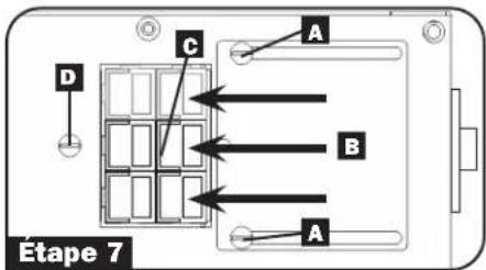
text_image
D C A B A Étape 7natural_image
Technical diagram of a rectangular enclosure with internal compartments and mounting points (no text or symbols)Spécifications
Messages de surcharge
1111 W. 35th Street, Chicago, IL 60609 USA • tripplite.com/support
21-11-122 93-2897_Rof
1111 W. 35th Street, Chicago, IL 60609 USA • tripplite.com/support
text_image
Diagram of an electronic device with labeled components including fan, control panel, and buttons
text_image
F G E 3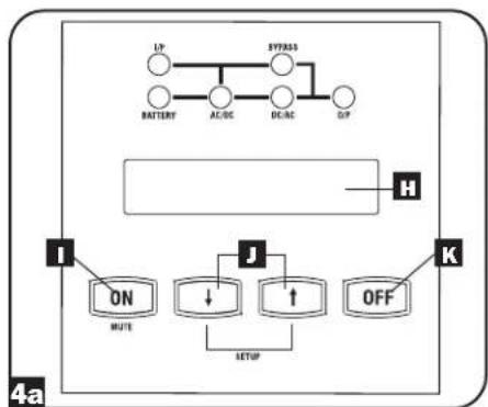
flowchart
graph TD
    A["LP"] --> B["BATTERY"]
    B --> C["AC/DC"]
    C --> D["DC/AC"]
    D --> E["GP"]
    F["H"] --> G["J"]
    G --> H["ON MUTE"]
    G --> I["SETUP"]
    G --> J["OFF"]
    K["K"] --> L["SETUP"]
    style A fill:#fff,stroke:#000
    style B fill:#fff,stroke:#000
    style C fill:#fff,stroke:#000
    style D fill:#fff,stroke:#000
    style E fill:#fff,stroke:#000
    style F fill:#fff,stroke:#000
    style G fill:#fff,stroke:#000
    style H fill:#fff,stroke:#000
    style I fill:#fff,stroke:#000
    style J fill:#fff,stroke:#000
    style K fill:#fff,stroke:#000
text_image
L M N O 4bПодключение
natural_image
Diagram of a plug socket with six circular socket heads, no text or symbols presentnatural_image
Diagram of an electronic device showing a power connector connected to a fan and drive unit (no text or symbols visible)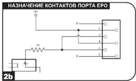
text_image
НАЗНАЧЕНИЕ КОНТАКТОВ ПОРТА ЕРО 12V x 1 2 3 4 5 6 1K x 2btext_image
ACI-SLDT RS-129 RS-128 RS-125 RS-124 RS-123 RS-122 RS-121 RS-120 RS-9 RS-8 RS-7 RS-6 RS-5 RS-4 RS-3 RS-2 RS-1 RS-0 3text_image
A E B WAR 1, 3, 4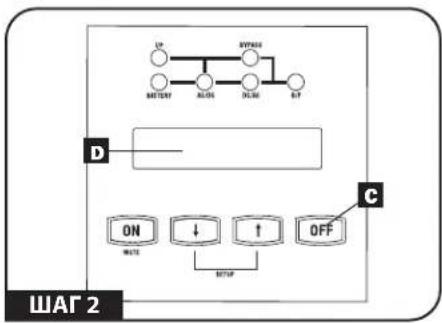
flowchart
graph TD
    A["UP"] --> B["BATTERY"]
    B --> C["ALON"]
    C --> D["OLUX"]
    D --> E["OFS"]
    F["D"] --> G["Switch"]
    H["ON"] --> I["WEAT"]
    J["↓"] --> K["SETUP"]
    L["↑"] --> M["OFF"]
    N["C"] --> O["Switch"]
natural_image
Technical line drawing of an electrical control panel with fan, buttons, and wiring (no text or labels)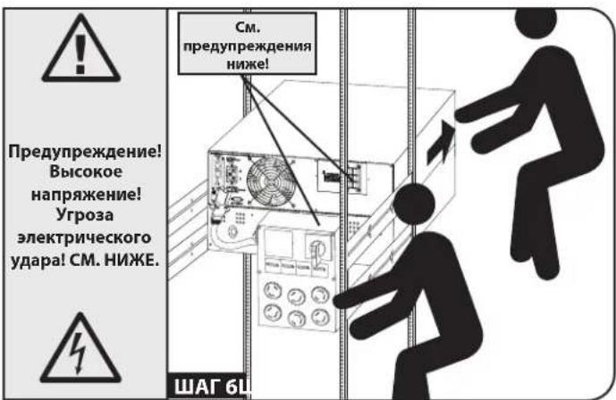
natural_image
Technical line drawing of an electrical control panel with buttons and wiring (no text or symbols)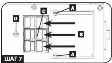
text_image
A B C D A ШАГ 7natural_image
Technical diagram of a device enclosure with an oval frame containing internal compartments and labeled component B (no text or symbols beyond label)1111 W. 35th Street, Chicago, IL 60609 USA • tripplite.com/support
21-11-122 93-2897_Rof