
DIN24240DC - Inverter Tripp Lite - Free user manual and instructions
Find the device manual for free DIN24240DC Tripp Lite in PDF.
| Product Type | DIN Rail DC UPS |
| Brand | Tripp Lite (Eaton) |
| Model | DIN24240DC |
| Dimensions (L x D x H) | 40 x 119 x 129 mm |
| Net Weight | 0.42 kg |
| Nominal Input Voltage | 24 V DC |
| Input Voltage Range | 21.6 – 28.6 V DC |
| Output Voltage | 24 V DC (V input – V output ≤ 0.6 V) |
| Maximum Output Current | 10 A |
| Efficiency | ≥ 95% (line and battery mode) |
| Built-in Battery Type | Lead-acid 12 V / 4.5 Ah × 2 in series |
| Backup Time (Full Load) | 10 minutes |
| Backup Time (Half Load) | 20 minutes |
| Recharge Time | < 8 hours |
| Protection | Overvoltage, undervoltage, overcurrent, short-circuit, overtemperature |
| Mounting | Omega DIN rail 35 mm (EN60715) |
| Indicators | Green LED (power/on battery), Red LED (fault) |
| Dry Contacts | Remote ON/OFF, alarms (on battery, low battery, etc.) |
| Operating Temperature | -15 °C to 50 °C |
| Humidity | 0 to 95% non-condensing |
| Maintenance | Check environment, clean area, inspect batteries |
| Safety | Lethal voltages – intervention by qualified personnel only |
| Spare Parts / Repairability | No user-serviceable parts – contact technical support |
Frequently Asked Questions - DIN24240DC Tripp Lite
User questions about DIN24240DC Tripp Lite
0 question about this device. Answer the ones you know or ask your own.
Ask a new question about this device
Download the instructions for your Inverter in PDF format for free! Find your manual DIN24240DC - Tripp Lite and take your electronic device back in hand. On this page are published all the documents necessary for the use of your device. DIN24240DC by Tripp Lite.
USER MANUAL DIN24240DC Tripp Lite
text_image
Power Fault RAT [1] [2] Power On/Off EAT·N DIN Rail UPS DIN24240DC Remote On/Off On Battery Replace Battery Battery Missing Low Battery COM Input Output [1] [1]+[1]
text_image
EAT•N DIN Rail UPS BPDIN24XLIMPORTANT SAFETY INSTRUCTIONS - SAVE THESE INSTRUCTIONS
This manual contains important instructions that you should follow during installation and maintenance of the UPS and batteries. Please read all instructions before operating the equipment and save this manual for future reference.
The Eaton Din Rail UPS models that are covered in this manual are intended for installation in an environment within —15 to 50°C, free of conductive contaminant.
The following are examples of symbols used on the product to alert you to important information:
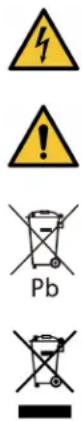
RISK OF ELECTRIC SHOCK - Observe the warning associated with the risk of electric shock symbol.
CAUTION: REFER TO OPERATOR'S MANUAL - Refer to your operator's manual for additional information, such as important operating and maintenance instructions.
This symbol indicates that you should not discard the product in the trash. This product must be disposed of properly. For more information, contact your local recycling/reuse or hazardous waste center.
This symbol indicates that you should not discard waste electrical or electronic equipment (WEEE) in the trash. For proper disposal, contact your local recycling/reuse or hazardous waste center.
Eaton reserves the right to change specifications without prior notice. Eaton is a registered trademark of Eaton. All other trademarks are properties of their respective companies. All other trademarks are property of their respective companies.
©Copyright 2022 Eaton, Raleigh, NC, USA. All rights reserved. No part of this document may be reproduced in any way without the express written approval of Eaton.
TTaabbllee ooff CCoonntteennttss
1 Safety & Warnings ....1
2 Overview ....3
2.2 Physical Features ....3
3 UPS Installation ....5
3.1 Mounting the UPS to the DIN Rail 5
3.2 DIN24240DC / DIN24480DC Input Wiring 7
4 EBM Installation....9
4.1 Mounting the EBM to the DIN Rail 9
4.2 Extended Battery Module Wiring 10
5 Operation....13
5.1 Startup and Normal Operation 13
5.2 UPS Shutdown 13
5.3 Battery Mode 13
5.4 UPS Self Test 13
6 Communications....15
6.1 UPS Dry Contacts 15
7 Maintenance....17
7.1 Routine Maintenance 17
7.2 Storage 17
8 Troubleshooting....19
8.1 Troubleshooting 19
9 Specifications....21
10 Warranty....23
10.1 Service and Support 23
1.1 Safety and Warnings
Read the following precautions before you install the UPS.
WARNING
• This UPS contains its own energy source (batteries).
• The DC mains power must be turned off before connecting or disconnecting wires to the terminals.
• Use RED wire for (+) positive and BLACK for (-) negative wire connections.
• Make sure the wires do not touch to chassis during their connection.
- Always connect the DC mains input and load output wires first, then the UPS battery terminals labeled (BAT +/-), and finally to the EBM.
- To reduce the risk of fire or electric shock, install this UPS in a temperature and humidity controlled, indoor environment, free of conductive contaminants. Ambient temperature must not exceed 50^ C ( 122^ F). Do not operate near water or excessive humidity (95% max).
- To comply with international standards and wiring regulations, the total equipment connected to the output of this UPS must not have an earth leakage current greater than 1.5 milliamperes.
- To guarantee sufficient convection cooling, please keep a clearance of 50mm above, 180mm below, and 10mm lateral distance of between devices.
- Note that the enclosure of the device can become very hot depending on the ambient temperature and load of the power supply. Risk of burns!
• Do not introduce any objects into the unit.
• The UPS and EBM unit should be installed in minimum IP54 rated enclosure.
- The units must be installed in a cabinet or room (condensation free environment and indoor location) that is relatively free of conductive contaminants.
! DANGER
This UPS contains LETHAL VOLTAGES. All repairs and service should be performed by AUTHORIZED SERVICE PERSONNEL ONLY. There are NO USER SERVICEABLE PARTS inside the UPS.
CAUTION
• For use in a controlled environment.
- Batteries can present a risk of electrical shock or burn from high short-circuit current. Observe proper precautions. Servicing should be performed by qualified service personnel knowledgeable of batteries and required precautions. Keep unauthorized personnel away from batteries.
• Proper disposal of batteries is required. Refer to your local codes for disposal requirements.
• Never dispose of batteries in a fire. Batteries may explode when exposed to flame.
Safety and Warnings
CChhaapptteerr 22 00vveerrvviiieeww
Thank you for purchasing your Eaton DIN24240DC or DIN24480DC UPS and BPDIN24XL extended battery module.
The Eaton DIN24240DC or DIN24480DC UPS power system (UPS) is a modular UPS that connects to BPDIN24XL Extended Battery Module.
The Eaton DIN24240DC or DIN24480DC UPS can accommodate up to four BPDIN24XL extended battery modules (EBM) to extend runtime. The UPS and EBM can be each model can be installed onto a 35mm "top hat" DIN rail in accordance with EN60715.
2.2 Physical Features
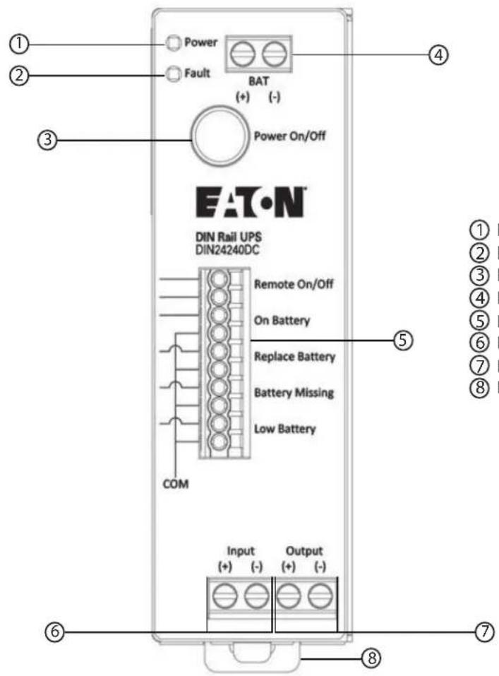
Figure 1. DIN24240DC / DIN24480DC UPS Features
text_image
Power Fault BAT (+) (-) Power On/Off EATON DIN Rail UPS DIN24240DC Remote On/Off On Battery Replace Battery Battery Missing Low Battery COM Input (+) (-) Output (+) (-) ① ② ③ ④ ⑤ ⑥ ⑦ ⑧① LED (Green) Input OK (Solid)/ On Battery (Flashing)
② LED (Red) - Fault
③ Power ON/Off Button
④ Battery Pack Terminal Block
⑤ Dry Contact Relay Terminals
⑥ DC Mains Input Terminal Block
⑦ DC Load Output Terminal Block
⑧ DIN Rail Mounting Clamp
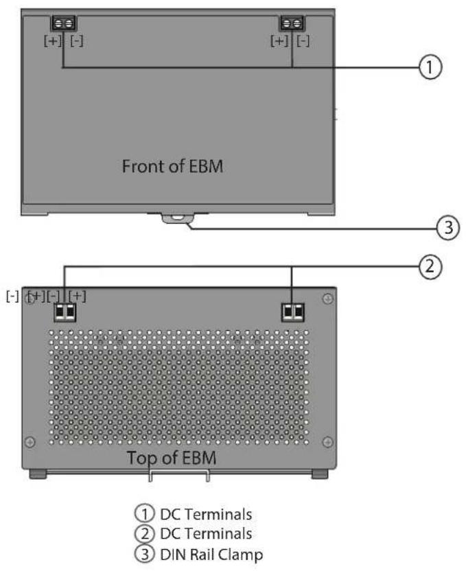
Figure 2. BPDIN24XL Features
text_image
Front of EBM ① ③ ② ④ ⑤ ⑥ ⑦ ⑧ ⑨ ⑩ ⑪ ⑫ ⑬ ⑭ ⑮ ⑯ ⑰ ⑱ ⑲ ⑳ ⑴ ⑵ ⑶ ⑷ ⑧ ⑨ ⑩ ⑪ ⑫ ⑬ ⑭ ⑮ ⑯ ⑰ ⑱ ⑲ ⑳ ⑮ ⑯ ⑰ ⑱ ⑲ ⑳ ㉑ ㉒ ㉓ ㉔ ㉕ ㉖ ㉗ ㉘ ㉙ ㉚ ㉛ ㉜ ㉝ ㉞ ㉟ ㉳ ㉟ ㉟a ㉟b ㉟c ㉟d ㉟e ㉟f ㉟g ㉟h ㉟i ㉟j ㉟k ㉟l ㉟m ㉟n ㉟o ㉟p ㉟q ㉟r ㉟s ㉟t ㉟u ㉟v ㉟w ㉟x ㉟y ㉟z ㉟a ㉟b ㉟c ㉟d ㉟e ㉟f ㉟g ㉟h ㉟i ㉟j ㉟k ㉟l ㉟m ㉟n ㉟o ㉟p ㉟q ㉟r ㉟s ㉟t ㉟u ㉟v ㉟w ㉟x ㉟yt ㉟z3.1 Mounting the UPS to the DIN Rail
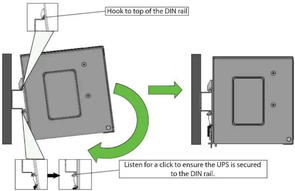
The EATON DIN24240DC and DIN24480DC UPS can be mounted on "top hat" 35mm DIN rail in accordance with EN60715.
To Mount the UPS:
- Locate the top hook of the DIN rail mounting system on the unit with the unit slightly titled.
- Rotate the unit till the latch of the rail mount system snaps on to the bottom of the DIN rail and the unit cannot be rotated any further.
- Shake the UPS slightly to ensure that it is secure.
- Check if the UPS is facing upright and not tilting downward.
Figure 3. Mounting the UPS
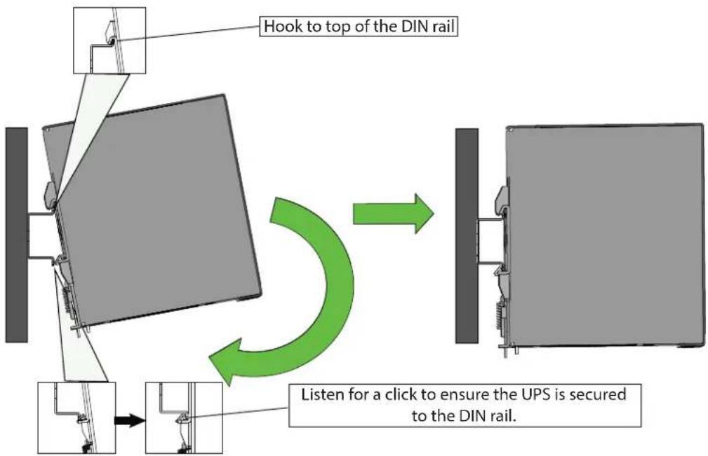
flowchart
graph TD
    A["Hook to top of the DIN rail"] --> B["Listen for a click to ensure the UPS is secured to the DIN rail."]
    B --> C["Next step"]
    style A fill:#f9f,stroke:#333
    style C fill:#bbf,stroke:#333
Adjusting the DC UPS on the DIN Rail
To adjust the UPS:
- To adjust the spacing between the DC UPS and EBMs, pull down the on the DIN rail clamp with a flathead screwdriver or tool to release the clamp.
- Tilt up slightly and adjust to desired spacing and snap back onto DIN rail.
- Shake the UPS slightly to ensure that it is secure.

NOTE
Maintain 0.39in (10mm) between devices, 1.97in (50mm) above, and 7.09in (180mm) below.
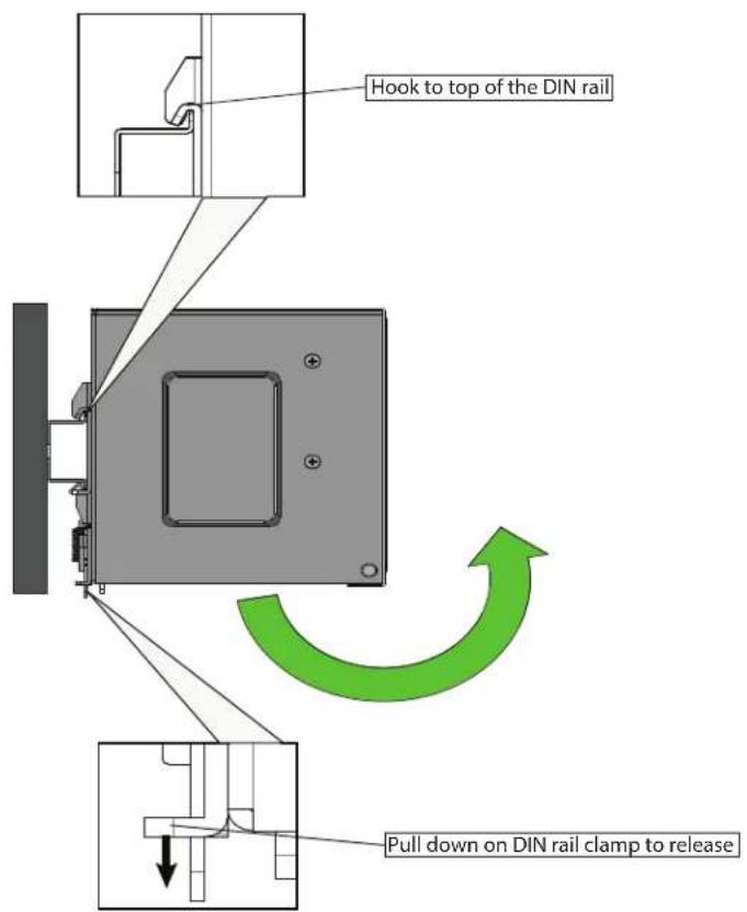
RReemmoovviinngg tthhee UUPPSS ffrroomm tthhee DDIINN RRaaiill
- Turn off the DC UPS and ensure that DC mains power is disconnected.
- Disconnect DC wiring between the DC UPS and any extended battery module DC wiring connections first.
- If multiple EBM's are to be disconnected, disconnect wiring between each EBM.
- Pull down the on the DIN rail clamp with a flathead screwdriver or tool to release the clamp.
- Tilt the UPS slightly and then up to remove from the DIN rail.
Figure 4. Removing UPS From DIN Rail
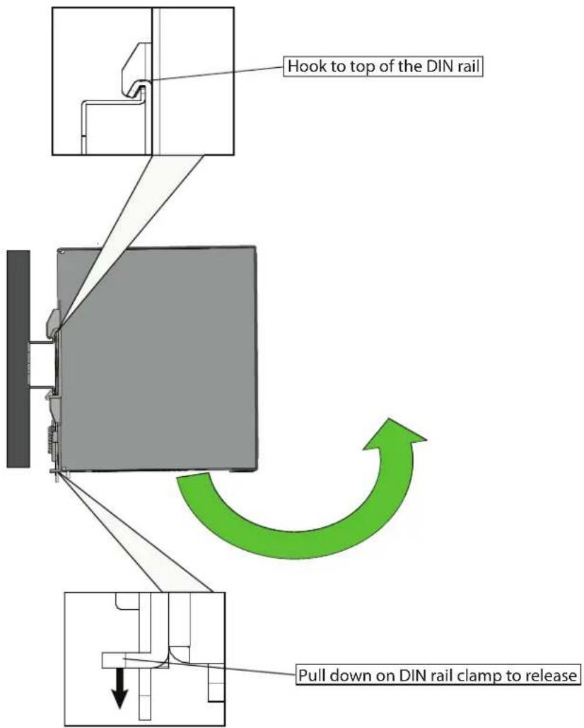
text_image
Hook to top of the DIN rail Pull down on DIN rail clamp to release33..22 DDIINN2244224400DDCC // DDIINN2244448800DDCC IInnppuutt WWiirriinngg
WARNING
Only qualified service personnel (such as a licensed electrician) should perform the electrical installation. Risk of electrical shock.
CAUTION
The circuit breaker or disconnect switch must also be OFF at the DC input service panel.
To install the DC input / output wiring to the UPS:
- Locate the DC Input / Output terminal blocks on the front of the UPS.
- Ensure that the proper wire gauge is being used per Table 1.
- Attach the DC +positive and —negative wires to the terminal block and torque to the specification.
Table 1. Recommended DC Input and Output Wire Sizes
| Terminal | Recommended Wire Gauge AWG (mm2) | Torque N-m (in-lb) | |
| DIN24240DC | DIN24480DC | ||
| DC Input/Output | 16 (1.5) | 12 (4) | 0.6 (5.3 in-lb) |
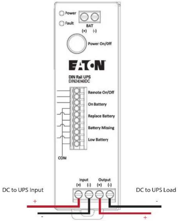
text_image
Power Fault BAT (+) (-) Power On/Off EAT•N DIN Rail UPS DIN24240DC Remote On/Off On Battery Replace Battery Battery Missing Low Battery COM DC to UPS Input Input (+) (-) Output (+) (-) DC to UPS Load + -DIN24240DC / DIN24480DC Input Wiring
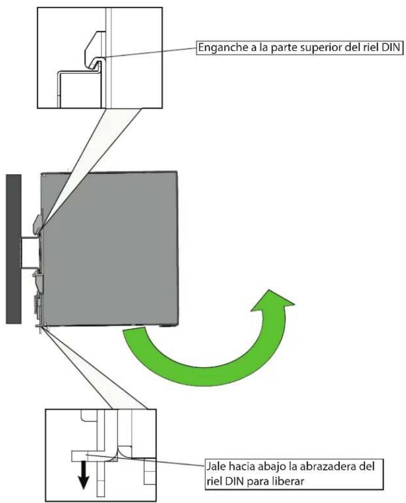
4.1 Mounting the EBM to the DIN Rail
To Mount the BPDIN24XL EBM:
- Locate the top hook of the DIN rail mounting system on the unit with the unit slightly titled.
- Rotate the unit till the latch of the rail mount system snaps on to the bottom of the DIN rail and the unit cannot be rotated any further.
- Shake the UPS slightly to ensure that it is secure.
- Check if the UPS is facing upright and not tilting downward.
- Add additional BPDIN24XL extended battery modules by following the above steps and ensure that each EBMs are at a minimum distance of 0.39in (10mm) between each module. Up to four EBM modules can be used per UPS.
Figure 5. Mounting the BPDIN24XL EBM
text_image
Hook to top of the DIN rail Listen for a click to ensure the UPS is secured to the DIN rail.Adjusting the DC UPS EBM on the DIN Rail
To adjust the EBM:
- To adjust the spacing between the DC UPS and EBMs, pull down the on the DIN rail clamp with a flathead screwdriver or tool to release the clamp.
- Tilt up slightly and adjust to desired spacing and snap back onto DIN rail.
- Shake the UPS slightly to ensure that it is secure.

NOTE
Maintain 0.39in (10mm) between devices, 1.97in (50mm) above, and 7.09in (180mm) below.
RReemmoovviinngg tthhee EEBBMM ffrroomm tthhee DDIINN RRaaill
- Turn off the DC UPS and ensure that DC mains power is disconnected.
- Disconnect DC wiring between the DC UPS and the extended battery module DC wiring connections first.
- If multiple EBM's are to be disconnected, disconnect wiring between each EBM.
- Pull down the on the DIN rail clamp with a flathead screwdriver or tool to release the clamp.
- Tilt the EBM slightly and up to remove from the DIN rail.
text_image
Hook to top of the DIN rail Pull down on DIN rail clamp to release4.2 Extended Battery Module Wiring
WARNING
Only qualified service personnel (such as a licensed electrician) should perform the electrical installation. Risk of electrical shock.
CAUTION
The DC mains power must be turned off before connecting or disconnecting wires to the battery terminals.
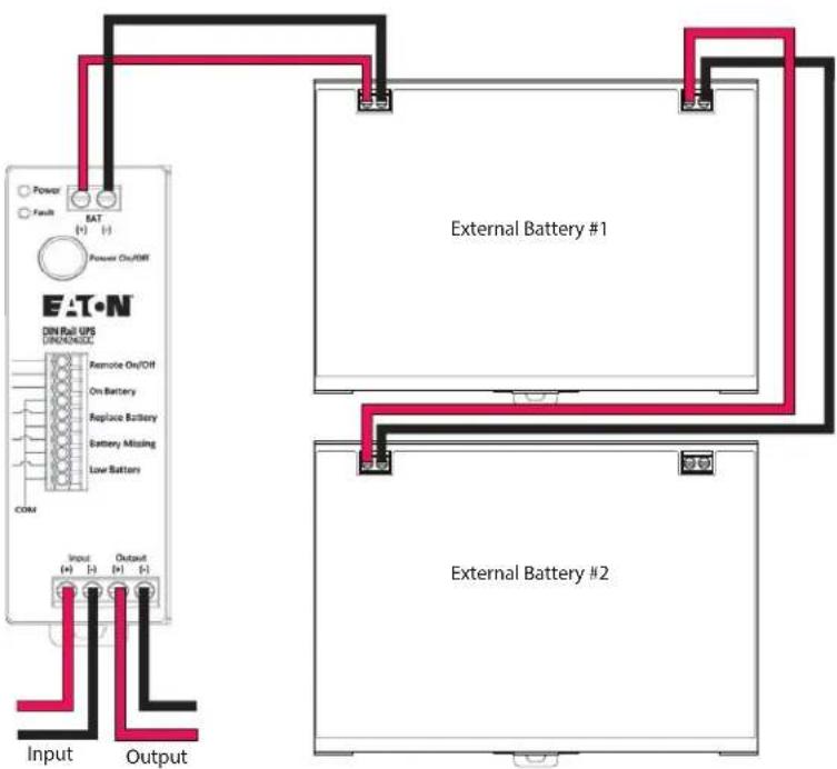
To install the DC input / output wiring to the UPS:
-
Locate the DC Input / Output terminal blocks on the top or front panel of the EBM.
-
Ensure that the proper wire gauge is being used per Table 2.
-
Strip the wire insulation back about 0.35 inches (9mm) of all positive and negative wires being used for DC Input/Output/Battery connections.
-
Insert the red wire into the EBM (+) terminal closest to the DIN Rail UPS or previous EBM (if multiple EBMs are being used).
-
Insert the black negative wire to the negative (-) terminal of the EBM closest to the DIN Rail DC UPS. Tighten the screws to the specified torque rating in .

IMPORTANT
For maximum contact and safety, please ensure that the DC cables wire strands are fully inserted inside the DC terminals.
-
With a voltmeter, verify that 24VDC is present across all positive and negative terminals.
-
Power the UPS ON, see 5.1 Startup and Normal Operation.
Figure 6. EBM Wiring
flowchart
graph TD
    A["Input"] --> B["External Battery #1"]
    C["Output"] --> D["External Battery #2"]
    B --> E["External Battery #1"]
    D --> F["External Battery #2"]
    G["DIN Rail UPS DIN/DIN/DIN"] --> H["Remote On/OFF"]
    H --> I["On Battery"]
    I --> J["Replace Battery"]
    J --> K["Battery Missing"]
    K --> L["Low Battery"]
    L --> M["COM"]
    M --> N["Power"]
    M --> O["Fault"]
    M --> P["Power On/OFF"]
    style A fill:#f9f,stroke:#333
    style C fill:#f9f,stroke:#333
    style G fill:#ccf,stroke:#333
    style D fill:#ccf,stroke:#333
Table 2. Recommended EBM Wire Size
| Connection | Wire Size (AWG) Torque | N-m (in-lb) |
| Battery Terminals 12 AWG (4 sq. mm) | 0.6 (5.3 in-lb) |
Extended Battery Module Wiring
5.1 Startup and Normal Operation
To Start the UPS:
- Ensure that the UPS input and output wiring are connected and that the correct voltage is being supplied to the UPS. See 3.2 DIN24240DC/DIN24480DC Input Wiring.
- Verify that the external batteries are connected. See 4.2 Extended Battery Module Wiring.
- Press the power ON/OFF button on the front of the UPS for three seconds.

NOTE
As long as live 24V DC is supplied to the UPS input terminals, the DC output terminals will be live in Bypass and Line operation modes.
- Verify that the green power LED illuminates solid indicating the UPS is operating normally and any loads are powered and protected.
- Check the UPS front panel to verify that there are no active faults. Do not proceed until all active faults are cleared see 8.1 Troubleshooting.
5.2 UPS Shutdown
To shut down the UPS:
- Press and hold the UPS ON/OFF button for three seconds. The UPS then transfers to the OFF mode and the green power LED turns off.
CAUTION
If you are planning on removing the UPS or EBM (if applicable) from the DIN rail ensure all sources of DC power have been disconnected and properly isolated.
5.3 Battery Mode
When the UPS is operating on battery mode the green power indicator will flash once per second. Once the battery capacity reaches the low battery the green power indicator will flash every 0.3 seconds.
5.4 UPS Self Test
The UPS self test feature is preformed automatically when the UPS has access to acceptable line voltage. If the battery voltage is less than 10VDC the unit will consider the battery as abnormal and fail the test. If the battery voltage is above 10VDC the UPS will initiate a 6 second battery charge.
Once the UPS is turned on via the ON/OFF button if the battery voltage drops below 18VDC the battery will be considered abnormal.
UPS Self Test
6.1 UPS Dry Contacts
The DC UPS supports Remote On/Off with Normally Closed signaling and Event Alarm notifications via dry-contact Normally Open signaling. The user must supply 26 AWG wire to support the length of the installation.
To connect to the UPS contacts:
- Strip insulation to 0.35 inches (9mm) of exposed copper wire.
- Insert each wire into the appropriate circular terminal slot(s) appropriate for your application. Press in firmly to lock in place.
- Slightly tug to ensure a secure wire insertion.
- To remove a wire from contact terminal, insert a small insulated screwdriver into the square hole to the right of terminal to release.
Terminal voltage and current ratings needed.
| Remote and Contact Alarm Pinout | |
| PIN 1 | Remote On/Off |
| PIN 2 | Ground |
| PIN 3 | On Battery |
| PIN 4 | Common Signal |
| PIN 5 | Replace Battery |
| PIN 6 | Common Signal |
| PIN 7 | Missing Battery |
| PIN 8 | Common Signal |
| PIN 9 | Low Battery |
| PIN 10 | Common Signal |
UPS Dry Contacts
CChhaapptteerr 77 MMaaiinntteennaannccee
7.1 Routine Maintenance
The Eaton DIN24240DC / DIN24480DC system is designed to provide years of trouble-free operation. Its internal control system checks the batteries and inverter periodically to ensure reliable operation.
The Eaton DIN24240DC / DIN24480DC UPS and optional external battery cabinets do require some attention to assure continued reliable service. Follow Eaton's recommended maintenance schedule, which includes:
- Check operating environment for clean, cool, dry conditions.
- Inspect and clean the area around the UPS
- Check the batteries.
For more information on preventive maintenance checks, contact your service representative
7.2 Storage
Ambient temperature range is -15^ to 40^ (5°F to 104°F). It is recommended to charge the UPS for at least 8 hours, then store the UPS covered and upright in a cool, dry location. Remove accessories and disconnect cables connected to the UPS to avoid unnecessary draining of the battery.
Extended Storage
During extended storage in environments where the ambient temperature is: -15^ to +40^ ( +5^ to +104^ ), charge the UPS battery every three months.
Storage
CChhaapptteerr 88 TTrroouubblleesshhoooottiinngg
8.1 Troubleshooting
| Problem | Possible Cause | Solution |
| UPS nonresponsive(No LEDs or alarm) | UPS is powered off | Press ON/OFF button for TWO (2) seconds. |
| UPS fault | Contact Tech support. | |
| The UPS is always operating in Battery Mode | Input may not be properly connected. | Check the input connection. |
| Input fuse is open | Before reconnecting equipment, verify the load matches the UPS capability specified and output has short circuit protection. Contact Tech support. | |
| Actual backup time cannot be achieved | Battery voltage is too low | Charge the battery at least eight (8) hours. |
| Overload | Remove unnecessary loads. Before reconnecting equipment, verify the load matches the UPS capability specified. | |
| Battery defect | Replace the battery. | |
| UPS fault or charger failure | Contact Tech support. | |
| Fault code displayed. | Overload | Remove unnecessary loads. Before reconnecting equipment, verify the load matches the UPS capability specified. |
| UPS short-circuit | Contact Tech support. | |
| UPS over temperature | Remove unnecessary loads. Before reconnecting equipment, verify the load matches the UPS capability specified. Make sure the UPS is installed in a pretested area that is free of excessive dust and has adequate air flow. Place the UPS away from other units at least 8int to avoid interference. For best performance, keep the indoor temperature between 0°C to 50°C. |
Troubleshooting
Table 3. DC Input Characteristics
| DIN24240DC | DIN24480DC | |
| Input Rated Voltage | 24VDC | |
| Input Rated Voltage | 21.6–28.6VDC | |
| Input Voltage Range | 22.6V±0.5V turn on to LM21.6V±0.5V turn off to BM28.6V±0.5V turn off to BM27.6V±0.5V turn on to LM | |
| Efficiency | Line mode : ≥ 95%Battery mode : ≥ 95% | Line mode : ≥ 95%Battery mode : ≥ 95% |
Table 4. DC Output Characteristics
| DIN24240DC | DIN24480DC | |
| DC Output Current | 0A~10A | 0A~20A |
| Line mode & Battery mode DC output voltage | Vin - Vout ≤ 0.6Vdc | |
| Turn on time | < 1s | |
| Transfer time | <10 ms | |
Table 5. Protection Characteristics
| DIN24240DC | DIN24480DC | |
| Input Over-Voltage Protection | < 30v | |
| Input Under-Voltage | >20v | |
| Over Current Protection | The output should to protect by auto-recovery mode.*Latch after 3 consecutive times if fault condition is not removed | |
| Short Circuit Protection | The output should to protect by auto-recovery mode*Latch after 3 consecutive times if fault condition is not removed(with battery condition) | |
| Over Temperature Protection | The output should to protect by auto-recovery mode | |
Table 6. Battery Characteristics
| DIN24240DC | DIN24480DC | |
| Battery Type | 12V/4.5AH * 2 lead acid battery in series | |
| Charging Current | < 0.75A | |
| Recharge time | < 8 hours | |
| Backup Time (Full Load) | 10 min. 3min. | |
| Backup Time (Half Load) | 20 min. 10min. | |
| Cut off voltage | 20V±0.5V 19.2V±0.5V | |
| Battery warming voltage | 20.8V±0.5V 20.0V±0.5V | |
| Battery leakage current | < 500uA | |
Table 7. Environment Characteristics
| DIN24240DC DIN24480DC | ||
| Ambient Operation 0–95% humidity, non-condensing. 50 °C at 3000 meters. | ||
| Audible Noise | <40 dB (Distance 15cm with product) | |
| Vibration Test | OperatingAxis : X,Y,ZFrequency, Power spectral density5.5Hz, 0.008 g ^2 /Hz10Hz, 0.001 g ^2 /Hz18Hz, 0.001 g ^2 /Hz29Hz, 0.004 g ^2 /Hz50Hz, 0.004 g ^2 /Hz200Hz, 0.001 g ^2 /HzOverall g(RMS) : 0.64gDuration : 15min. | |
| Shock Test | Non-operatingHalf Sine Wave : 30g for duration of 11ms, 1 shocks for X, Y, Z-axis direction | |
Table 8. Weight and Dimensions
| DIN24240DC DIN24480DC | ||
| Net Weight,kg | 0.42 | |
| W X D X H,mm | 40 x 119 x 129 | |
Table 9. Certifications
| DIN24240DC DIN24480DC | ||
| Safety | cTUVus — UL 1778, 5th Ed./CSA 107.3.CE /LVD EN 62040-1 | |
| EMC | FCC Part 15, Subpart B,CE– EMC Directive – EN62040-2; EN55032; EN 55011, EN 55024, EN 61000-6-1,EN 61000-6-2, EN 61000-6-3, EN 61000-6-4, EN61000-3-2,EN 61000-3-3, IEC/EN 61000-4 Series | |
10.1 Service and Support
If you have any questions or problems with the UPS, call your Local Distributor or the Help Desk at one of the following telephone numbers and ask for a UPS technical representative.
United States:
1-800-356-5737
Canada:
1-800-461-9166 ext 260
All other countries:
Call your local service representative
Please have the following information ready when you call the Help Desk:
- Model number
- Serial number
• Version number (if available)
• Date of failure or problem
• Symptoms of failure or problem
- Customer return address and contact information
If repair is required, you will be given a Returned Material Authorization (RMA) Number. This number must appear on the outside of the package and on the Bill Of Lading (if applicable). Use the original packaging or request packaging from the Help Desk or distributor. Units damaged in shipment as a result of improper packaging are not covered under warranty. A replacement or repair unit will be shipped, freight prepaid for all warranted units.

NOTE
For critical applications, immediate replacement may be available. Call the Help Desk for the dealer or distributor nearest you.
UPS de CD Eaton para riel Din DIN240DC / DIN24480DC / BPDIN24XL
text_image
Power Fault RAT [1] [2] Power On/Off EAT·N DIN Rail UPS DIN24240DC Remote On/Off On Battery Replace Battery Battery Missing Low Battery COM Input Output [1] [1]+[1]
text_image
EAT•N DIN Rail UPS BPDIN24XL©Copyright 2022 Eaton, Raleigh, NC, USA. All rights reserved. No part of this document may be reproduced in any way without the express written approval of Eaton.
TTaabbllee ooff CCoonntteennttss
Figure 4. Removing UPS From DIN Rail
text_image
Power Fault RAT [1] [2] Power On/Off EAT·N DIN Rail UPS DIN24240DC Remote On/Off On Battery Replace Battery Battery Missing Low Battery COM Input Output [1] [1]+[1]
text_image
EAT•N DIN Rail UPS BPDIN24XLCONSIGNES DE SÉCURITÉ IMPORTANTES CONSERVER CES INSTRUCTIONS
©Copyright 2022 Eaton, Raleigh, NC, USA. All rights reserved. No part of this document may be reproduced in any way without the express written approval of Eaton.
TTaabbllee ooff CCoonntteennttss
6 Communications....15
Table 9. Certifications
| DIN24240DC DIN24480DC | ||
| Sécurité | cTUVus— UL 1778, 5e éd./CSA 107.3.CE/LVD EN 62040-1 | |
| CEM | FCC Partie 15, sous-partie B,CE— Directive EMC — EN62040-2; EN55032; EN 55011, EN 55024, EN 610EN 61000-6-2, EN 61000-6-3, EN 61000-6-4, EN61000-3-2,EN 61000-3-3, série IEC/EN 61000-4 | |