
Compact ElectricHeat - Swimming Pool ASTRALPOOL - Free user manual and instructions
Find the device manual for free Compact ElectricHeat ASTRALPOOL in PDF.
| Product type | Electric heat exchanger for swimming pool or spa |
| Brand | AstralPool |
| Model | Compact ElectricHeat |
| Category | Pool |
| Power supply | Single-phase 230 V AC 50 Hz or three-phase 400 V AC 50 Hz (depending on model) |
| Available powers | 3 kW, 6 kW, 9 kW, 12 kW, 18 kW |
| Required water flow | 2.5 to 15 m³/h |
| Operating range | +5 °C to +45 °C |
| Maximum humidity | 90% without condensation |
| Max. installation angle | 20° from vertical |
| Pipe connection | 63 mm outer diameter (50 mm adapters supplied) |
| Required electrical protection | 30 mA residual current circuit breaker |
| Display | LCD screen with inlet/outlet temperatures, setpoint, flow, power |
| Temperature adjustment | Using + and - keys, °C or °F scale |
| Clock operation | Yes, via external filtration timer |
| Modbus communication | Available (specific models) |
| Heat exchanger material | Incoloy or titanium depending on version (check compatibility with water treatment) |
| Warranty | 2 years from date of purchase |
| Winter maintenance | Drain the unit to prevent frost damage |
| Main spare parts | Heating elements, triacs, flow switch, temperature sensors |
Frequently Asked Questions - Compact ElectricHeat ASTRALPOOL
User questions about Compact ElectricHeat ASTRALPOOL
0 question about this device. Answer the ones you know or ask your own.
Ask a new question about this device
Download the instructions for your Swimming Pool in PDF format for free! Find your manual Compact ElectricHeat - ASTRALPOOL and take your electronic device back in hand. On this page are published all the documents necessary for the use of your device. Compact ElectricHeat by ASTRALPOOL.
USER MANUAL Compact ElectricHeat ASTRALPOOL
Thank you for purchasing the new COMPACT® Electric heat exchanger. The experience our company gas gained over more than 25 years in the world of pool conditioning has been put to your service in this product.

INFORMATION
Please, read this manual carefully to ensure that your new heater will give you years of trouble free service. Remember that incorrect installation will affect your warranty.
Do not discard this manual, please, keep it for future reference.
It is recommended to take note of the following data:
INSTALLER COMPANY:
INSTALLER TELEPHONE:
INSTALLATION DATE:
HEATER MODEL:
HEATER SERIAL NUMBER:
DEALER'S STAMP INSTALLER'S STAMP

WARNING
This heater must be installed in a dry weatherproof enclosure.
Operating temperature range: +5°C to +45°C
Max operating Humidity: 90% without condensation.
If the heater is not used for a long period of time (winter), it must be drained to prevent damage.
2 PRODUCT DESCRIPTION
This COMPACT® Electric heat exchanger is designed to accurately achieve the temperature desired on your pool or spa. It is always aware of the actual water temperature and desired one and reacts instantly thanks to its new electronic control, far more accurate than electro-mechanic ones.
The software that controls this unit is so powerful and accurate that even connects or disconnects single heating elements depending on the actual heating needs at every single time, so when you need to quickly heat the water, it will connect the full power of the unit, but once set point is reached, the unit will automatically manage heating elements to connect or disconnect them depending of heat demand.
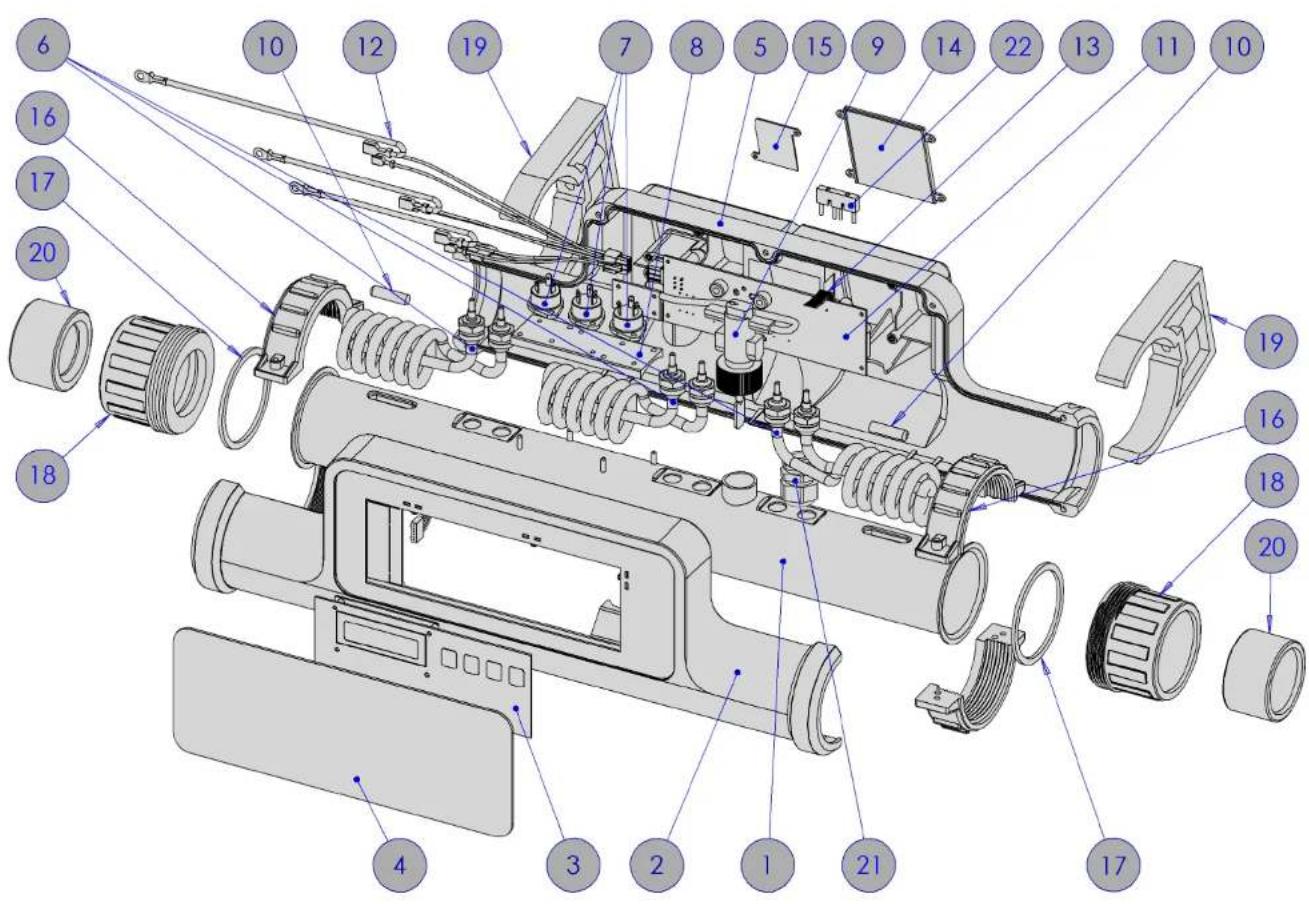
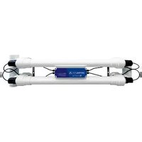
You can see a detailed product parts overview on image 1.
3 INSTALLATION
This heater has many installation possibilities, but always respecting some guidelines.
3.1 POSITIONING
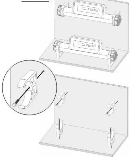
This heater can be installed on a horizontal surface or in a vertical one.
Holding claps are just to be rotated to the desired alignment. Remember, holding clamps are to be screw fixed securely to a firm flat wall or base. See images 2.
WARNING
Remember leaving sufficient clear space around the unit to ease pipe connections and servicing.
Unit can be positioned up to 20^ angle respect to the vertical. See images 3.

ATTENTION
Heater must be installed in a horizontal position, no vertical installation is allowed. Warranty void if not respected. See image 4.
3.2 PIPING DETAILS
- The heater is ready to connect to a 63mm (external diameter) pipe work, but adapters are supplied to be able to connect to a 50mm (external diameter) piping system as well.
- The heater should be installed at a low point in the filtration system.
- A check valve is recommended to prevent the heater from running out of water.
- A by-pass is also recommended to ensure a correct water flow through the heater.
- Heater must be installed after (downstream) the filter and before (upstream) chlorinator or any other water treatment device.

ATTENTION
Heater must be installed after (downstream) the filter and before (upstream) any water treatment device. Warranty void if not respected.
See image 5 for recommended installation.
3.3 ELECTRICAL CONNECTION
- Electrical connection must be carried out by a qualified professional in accordance with the country/regional requirements & regulations.
- Remove terminals cover to make the connections, See image 7.
• Install power supply cord according to images 8.

ATTENTION
Power supply must be fitted with a 30 mA. RCD (Residual-Current Device). Serious damages may occur both to heater and installation if not respected. Warranty void if not respected.
- All heaters are capable of a monophasic ^ (1Phase+Neutral 230V AC 50 Hz.) or triphasic (3Phase+Neutral 400V AC 50 Hz.) supply voltage. If monophasic supply, loom (supplied) connection is required. See images 9.
3.4 POWER REQUIREMENTS
HEATER MODEL VOLTAGE (V) AMP (A)
| 3 kW | 230 / 400 | 13 / 4 |
| 6 kW | 230 / 400 | 26 / 9 |
| 9 kW | 230 / 400 | 40 / 13 |
| 12 kW | 400 | 18 |
| 18 kW | 400 | 27 |
CABLE SECTION
General rule for supply cable is 1mm^2 section for each 5 amp for distances up to 20 meters, though this has to be checked and adapted for each installation and for lengths over 20 meters and always in accordance with the country/regional requirements & regulations.
3.5 ELECTRICAL DIAGRAM See image 10.
3.6 FLOW REQUIREMENTS
This heater is factory set to a water inlet on the right side and water outlet on the left. If final user needs is to reverse the water flow, see next chapters.

ATTENTION
Water flow through heater must never exceed 15 m^3/hour . Warranty void if not respected.
If water flow above 15m^3/h is present, a bypass has to be installed to reduce flow through heater. The heater must detect water flow to operate. The minimum detectable water flow is 2,5m^3/h .
3.7 WATER QUALITY REQUIREMENTS
Water quality must be within the following limits:
| HCLO + CLO 4 ppm | ISOCIANURIC ACID: Up to 100 ppm | |
| PH: 6,0 – 8,0 | CaCO3 Up to 250 ppm | |
| CHLORIDES: | Up to 250 ppm | HBrO: Up to 8 ppm |

ATTENTION
Incoloy heaters are NOT suitable for use on saline (salt) pools. ONLY titanium heaters are suitable for use on saline (salt) pools. Warranty void if not respected.
3.8 CHANGING DEFAULT FLOW DIRECTION
Factory default flow direction is from right to left. If changing default flow direction is needed follow the steps described on images 11.

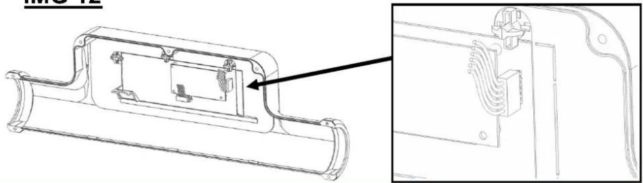
WARNING
Remember: if flowswitch is reversed, so has to be the connector of temperature probes. See images 13.
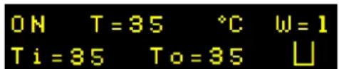
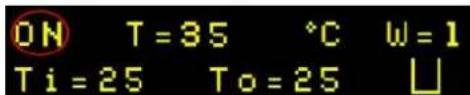
4 START-UP AND OPERATION
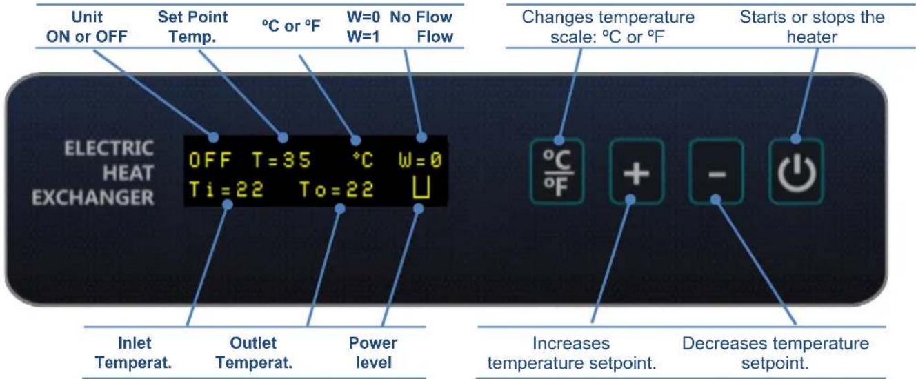
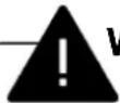
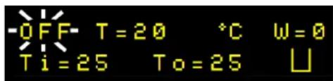
The unit will show if it is heating water by means of this icon on the lower right side of the screen:
Heating water at 2/3 of total power of the unit happens to achieve a soft start and when the water temperature is close to the set point to achieve a soft set point reach.
1) Once installation of the heater is complete, connect electrical supply to the unit. The screen will display that the unit is off and that there is no water flow.
2) Press "+" or "-" buttons to set the desired set point temperature. If necessary press "°C/°F" button to set your preferred temperature scale.
3) Then start the filtration pump to start water flow and purge the system of air. The screen will show that now there is water flow.
4) Then press Start / Stop button, to activate the heater.
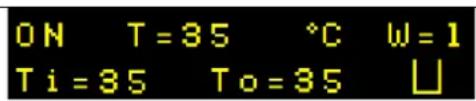
5) At this point the heater will start heating water if water temperature is below set point. On the other hand, if water temperature is equal or greater than set point the unit will remain idle.
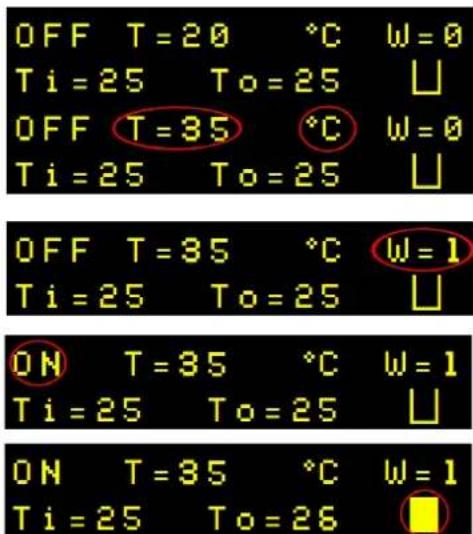
6) If the unit is heating water, it won't stop until set point is reached or heater is stopped.
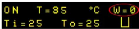
5 TIME CLOCK
This heater can work aside a time clock. Just set the desired temperature on the heater and switch it on.
While the pump is idle, so will be the heater. When the filtration pump starts working the heater will detect it and will heat the water if needed.

6 TROUBLE SHOOTING
UNIT SCREEN DOES NOT LIGHT UP
CAUSE #1: Power failure external to the heater.
SOLUTION #1: Check and fix power supply.
CAUSE #2: Power PCB or logic PCB failure.
SOLUTION #2: Check and replace if necessary.
UNIT WORKS INTERMITENTLY
CAUSE #1: Water flow near minimum value.
SOLUTION #1: Check water flow and increase it if necessary.
CAUSE #2: Water flow near minimum value due to dirt in filter.
SOLUTION #2: Back wash the filter to restore flow.
UNIT IS SWITCHED ON BUT IT IS NOT HEATING WATER
CAUSE #1: Check if temperature set point has been reached. If so, the unit is not heating water since water already has desired temperature:
CAUSE #2: Check if there is water flow. If water flow is not detected by the heater, the unit is not allowed to heat water:
CAUSE #3: If thermal cut out has tripped: the unit will remain auto-off and wait until inlet & outlet temperatures fall below a normal value and a manual reset.
SOLUTION #3: Just wait until reset temperature is reached and power back on the unit.
If this is proved to be the case, it has to be further investigated since thermal cut out only takes place at high water temperatures. For example, check for air bubbles on the system.
CAUSE #4: Flowswitch failure.
SOLUTION #4: Check if flow switch is working properly and replace if necessary.
RCD SWITCHS IMMEDIATELY AFTER POWERING ON THE HEATER
CAUSE: One or more triacs failure due to a high voltage peak from electrical supply.
SOLUTION: Replace triacs.
UNIT IS SWITCHED ON AND WORKING BUT AFTER MANY TIME NO WARMER WATER APPRECIATED
CAUSE: Heating elements out of order.
SOLUTION: Check resistance between the poles of the heating elements. Replace if necessary.
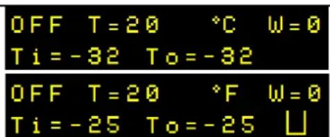
DISPLAY SHOWS INCORRECT TEMPERATURE: -32°C / -25°F
CAUSE: Temperature flow connector is incorrectly connected.
SOLUTION: Check that all pins in the connector are correctly connected. Check images N°13.
7 MODBUS
Modbus models include Modbus capabilities. For complete instructions for Modbus connection & communication, please consult Modbus manual at Fluidra PDB (Product Data Base): https://www.astralpool.com/en/products/

8 PRODUCT RECYCLING
When this electrical heat exchanger reaches the end of its service life, it must not be treated as household waste.
By ensuring that this product is disposed correctly you will help to reduce the amount of electrical and electronic residues, thus contributing to conserve natural resources.
To act responsibly, two possibilities are available:
- Hand the product over to the distributor or reseller that sold the unit.
• Take personally the unit to the applicable collection point.
9 WARRANTY CERTIFICATE

INFORMATION
This electrical heat exchanger has a 2 year guarantee, from the date of purchase, against faulty workmanship and materials.
1. - WARRANTY COVERAGE
1.1 In accordance with these provisions, the salesman guarantees that the product corresponding to this warranty (“the product”) does not present any non-conformance at the moment of its delivery.
1.2 The warranty period of the product is of two (2) years and it will take effect as of the time of delivery to the buyer.
1.3 If a Product non-conformance occurs and the buyer notifies it to the salesman during the Warranty Period, the salesman should repair or replace the Product at his own cost in the appropriate place, unless it is impossible or disproportionate.
1.4 When the Product cannot be repaired nor be replaced, the buyer shall be able to ask for a proportional price reduction or, if the non-conformance is sufficiently important, the discharge of the sales contract.
1.5 The replaced or repaired parts by virtue of this warranty will not extend the warranty term of the original Product, although they will have its own warranty.
1.6 For the effectiveness of this warranty, the buyer will have to credit the acquisition date and delivery date of the Product.
1.7 When the delivery of the Product to the buyer had been more than six months before and the buyer alleges non-conformance with the product, the buyer will have to prove the origin and existence of the alleged fault.
1.8 The present Warranty Certificate does not limit or prejudices the rights the consumers are entitled by virtue of local prevailing and applicable regulations.
2. - CONDITIONS TO WARRANTY
2.1. This warranty covers the products referred to in this manual.
2.2. For the effectiveness of this warranty, the buyer will have to strictly follow the manufacturer instructions included in the documentation enclosed with the Product, whenever this warranty is applicable according to the Product range and model.
2.3. When a calendar for the substitution, maintenance or cleaning of certain parts or components of the Product is specified, the Warranty will only be valid when the calendar has been observed.
3. - LIMITATIONS
3.1. This warranty will be solely applicable to those sales to consumers, being understood "consumers" as those people who acquire the Product with a purpose that does not fall within the scope of their professional activity.
3.2. No warranty is granted referred to the wear and tear caused by the use of the Product. In relation to the parts, components and/or consumable materials such as batteries, light bulbs etc; it will refer to the provisions of the documentation enclosed with the Product, when applicable.
3.3. The warranty does not cover those cases where the Product: (I) has been incorrectly treated; (II) has been repaired, maintained or manipulated by a nonauthorized person, or (III) has been repaired or maintained with non-original pieces.
3.4. When the non-conformance of the Product is a consequence of an incorrect installation or start-up, this warranty will only cover those installations or start-ups included in the contract of sale of the Product and carried out by the salesman or under his/her responsibility.
TABLA DE CONTENIDOS
1 INTRODUCCION ...... p.1
2 DESCRIPCION DEL PRODUCTO......p.2
3 INSTALACION ...... p.2
3.1 POSICIONAMIENTO......p.2
3.2 DETALLES DE TUBERIAS....p.2
3.3 CONEXION ELECTRICA ...... p.3
3.4 REQUERIMIENTOS DE POTENCIA..... p.3
3.5 DIAGRAMA ELECTRICO ..... p.3
| HCLO + CLO 4 ppm | ACIDO ISOCIANURICO: Up to 100 ppm | |
| PH: 6,0 – 8,0 | CaCO3 Up to 250 ppm | |
| CLORUROS: | Up to 250 ppm | HBrO: Up to 8 ppm |

ATENCION
8 RECICLAJE DEL PRODUCTO
| HCLO + CLO 4 ppm | ACIDE ISOCYANIQUE Up to 100 ppm | |
| PH: 6,0 – 8,0 | CaCO3 Up to 250 ppm | |
| CHLORURES: | Up to 250 ppm | HBrO: Up to 8 ppm |

ATTENTION
8 RECYCLAGE DU PRODUIT
| HCLO + CLO 4 ppm | ISOCYANURSÄURE: Up to 100 ppm |
| PH: 6,0 – 8,0 | CaCO3 Up to 250 ppm |
| CHLORID: Up to 250 ppm | HBrO: Up to 8 ppm |

ACHTUNG
https://www.astralpool.com/en/products/

MODELO VOLTAGEM (V) AMP (A)
| 3 kW | 230 / 400 | 13 / 4 |
| 6 kW | 230 / 400 | 26 / 9 |
| 9 kW | 230 / 400 | 40 / 13 |
| 12 kW | 400 | 18 |
| 18 kW | 400 | 27 |
SECÇÃO DO CABO
https://www.astralpool.com/en/products/

Water quality must be within the following limits:
/ Stop button, to activate the
https://www.astralpool.com/en/products/

| 1 | END FITTINGS TERMINALES ANCLAJE RACCORDS D'EXTRÉMITÉ | PAKOP | ||
| ENDARMATUREN RACCORDI TERMINALI RACORES FINAIS | ΣΥΝΔΕΣΗΣ | |||
| 2 | FRONT COVER | TAPA FRONTAL | COUVERCLE FRONTAL | ΜΠΡΟΣΤΑ |
| ΚΑΠΑΚΙ FRONT-DECI | ||||
| 3 | DISPLAY | PANTALLA | ÉCRAN | ΟΘΟΝΗ |
| LAMPENSCHIRM SCHERMATA | ECRÃ | |||
| 4 | USER BUTTONS BOTONES DE USUARIO BOUTONS UTILISATEUR ΠΛΗΚΤΡΑ | ΛΕΙΤΟΥΡΓΙΑΣ | ||
| USERBUTTONS | PULSANTI UTENTE | BOTÕES DO UTILIZADOR | ||
| 5 | HOLDING CLAMPS GRAPAS DE FIJACION GRAMPOS DE FIXAÇÃO | ΣΤΗΡΙΓΜΑΤΑ | ||
| HALTEKLAMMERN | COLLARI DI PRESA | SEGURANDO PINÇAS | ||
| 6 | BACK COVER | TAPA TRASERA | COUVERCLE ARRIÈRE | ΠΙΣΩ ΚΑΠΑΚΙ |
| RÜCK-DECKEL | COPERCHIO DIDIETRO | TAMPA TRASEIRA | ||
| 7 | TERMINALS COVER | TAPA DE BORNAS COUVERCLE BORNES | AKPOKIBΩΤΙΟ | |
| KLEMMEN-DECKEL | COPERCHIO MORSETTO | TAMPA DE BORNES | ΣΥΝΔΕΣΗΣ | |
| 8 | CABLE GLAND | PASAMUROS | TRAVERSE À PAROI | ΣΤΥΠΙΟΘΛΙΝΤ |
| WANDDURCHFÜHRUNG | PASSAMURI | PASAMUROS | ΗΣ | |
| 9*** | MODBUS COVER | TAPA CAJA MODBUS | COUVERCLE MODBUS | MODBUS |
| MODBUS-DECKEL | COPERCHIO MODBUS | TAMPA MODBUS | ΚΑΠΑΚΙ | |
IMGS 2 IMGS 3 IMG 4
natural_image
Technical illustration of a mechanical clamp device with a magnified inset showing the pin alignment (no text or symbols present)Horizontal & Vertical Mounting.
Max installation angle.
natural_image
Technical line drawing of a mechanical component with mounting flanges and a control panel (no text or symbols)Vertical installation not allowed.
Locate cable gland Insert cable Screw cable gland to form seal
natural_image
Electrical wiring diagram showing connections between components (no text or symbols visible)Monophasic connection. 3, 6 and 9 kW models.
Triphasic connection. All models.
natural_image
Technical line drawing of a mechanical component with no visible text or symbolsUnscrew the 7 screws at the back cover
Desatornillar los 7 tornillos de la carcasa trasera
Dévisser les 7 vis du couvercle arrière
Die 7 Schrauben am Rückdeckel aufschrauben
Svitare le 7 vite del coperchio posteriore
Desapertar os 7 parafusos da tampa traseira
Ξεβιδώστε τις 7 βίδες στο πίσω μέρος
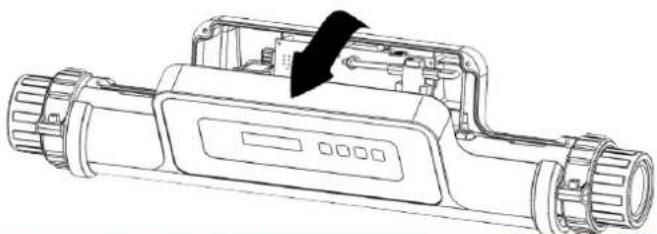
natural_image
Technical line drawing of a handheld electronic device with a black arrow indicating a component (no text or symbols present)Dettatch the front cover
Desmontar la carcasa frontal
Démonter le couvercle frontal
Den Frontdeckel entfernen
Levare il coperchio frontale
Desmontar a tampa frontal
Αφαιρέστε το μπροστινό μέρος
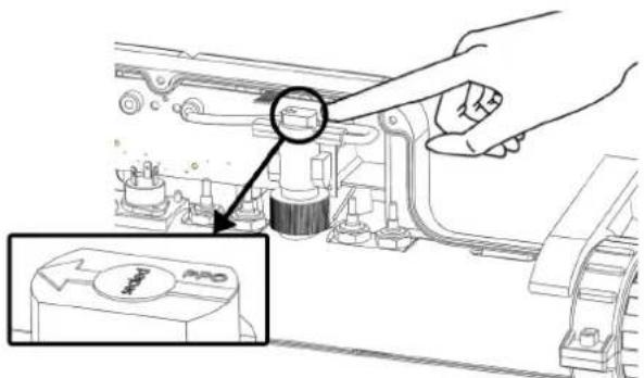
Locate flowswitch. Flow direction is shown by the arrow on top.
(Default: right to left)
Localizar el flujostato. La dirección del flujo viene dada por la flecha superior. (Por defecto drcha. a izq.)
Localiser le détecteur de débit. La direction du débit est indiquée par une flèche en haut. (Ex usine de droite à gauche).
Den Durchflussschalter auffindig machen. Die Wasserrichtung wird mit einem Pfeil angezeigt (werksseitig von rechts nach links eingestellt)
Localizzare il flussostato. La direzione e indicata con una freccia in alto. (Franco fabbrica da destra a sinistra).
Localizar o fluxostato. O sentido do fluxo é indicado pela seta superior. (Por defeito dta. para a esq.)
Εντοπίστε το διακόπτης ροής .Η διεύθυνση της ροής φαίνεται από το βέλος ψηλά. ( Εργοστασιακά είναι από δεξιά στα αριστερά )
natural_image
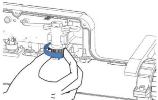
Line drawing of a hand operating a mechanical device with a blue tool inserted (no text or symbols visible)Unscrew nut until flowswitch main part is able to rotate.
Do not unscrew totally!
Desenrroscar el flujostato hasta que el cuerpo pueda girar. ¡No
desenroscar por completo!
Dessesrrer le détecteur de débit à palette jusqu'à que la partie puisse virevolter. Ne pas desserrer complètement!
Den Durchflussschalter abschrauben bis dieser nicht mehr aufdreht. Nicht komplett aufschrauben!
natural_image
Hand holding a mechanical component with a blue circular arrow indicating rotation (no text or symbols visible)Rotate flowswitch main part 180° until arrow points left to right.
Girar el cuerpo del flujostato 180° hasta que la flecha apunte de izda a drcha.
Tourner le détecteur de débit de 180° jusqu'à que la flèche indique de gauche à droite.
Den Durchfluss-Körper drehen um 180°bis der Pfeil von links nach rechts zeigt.
Girare il flussotato a 180° fino a che la freccia indichi da sinistra a destra.
Girar o corpo do fluxostato 180° até que a seta indique da esq. para
a dta.
Περιστρέψτε τον διακόπτης ροής 180 μέχρι το βέλος να δείξει στα δεξία
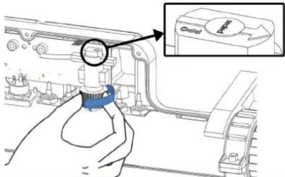
Screw nut back and ensure that it is completely locked to achieve desired watertightness.
Volver a enrroscar el flujostato hasta que quede perfectamente
ajustado para conseguir la estarqueid ad.
Revisser le détecteur de débit de nouveau jusqu'à ce qu'il soit parfaitement ajuster et étanche.
Den Durchflussschalter wieder einschrauben bis dieser perfekt eingeschraubt ist um die Dichtheit sicher zu stellen.
Avvitare di nuovo fino a che sia perfettamente calzato e stangno.
Voltar a enroscar o fluxostato até ficar perfeitamente ajustado para
conseguir a estanqueidade
Βιδώστε πίσω το παξιμάδι και εξασφαλίστε ότι είναι σφραγισμένο για να υπάρχει στεγανότητα)
IMG 12
natural_image
Technical line drawing of a mechanical component with internal parts and an inset view (no text or symbols)Factory setting: water enters through the right side of the heater and exits through the left side.
natural_image
Pure technical line drawing of a mechanical component with no text or symbols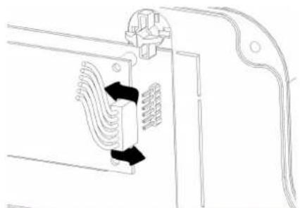
natural_image
Pure technical line drawing of a mechanical component with no text or symbolsPull back connector to disconnect it. Flip the connector.
natural_image
Technical line drawing of a mechanical component with a curved bracket and mounting bracket (no text or symbols)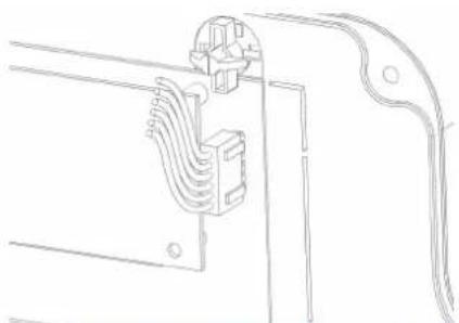
natural_image
Pure technical line drawing of a mechanical or electrical component with no text, numbers, or symbolsReconnect. Be particularly careful to connect all pins.
Final aspect for water inlet through the left side of the heater.
Press to modify offset.
Presionar para modificar offset.
Press to change between inlet & outlet temp.
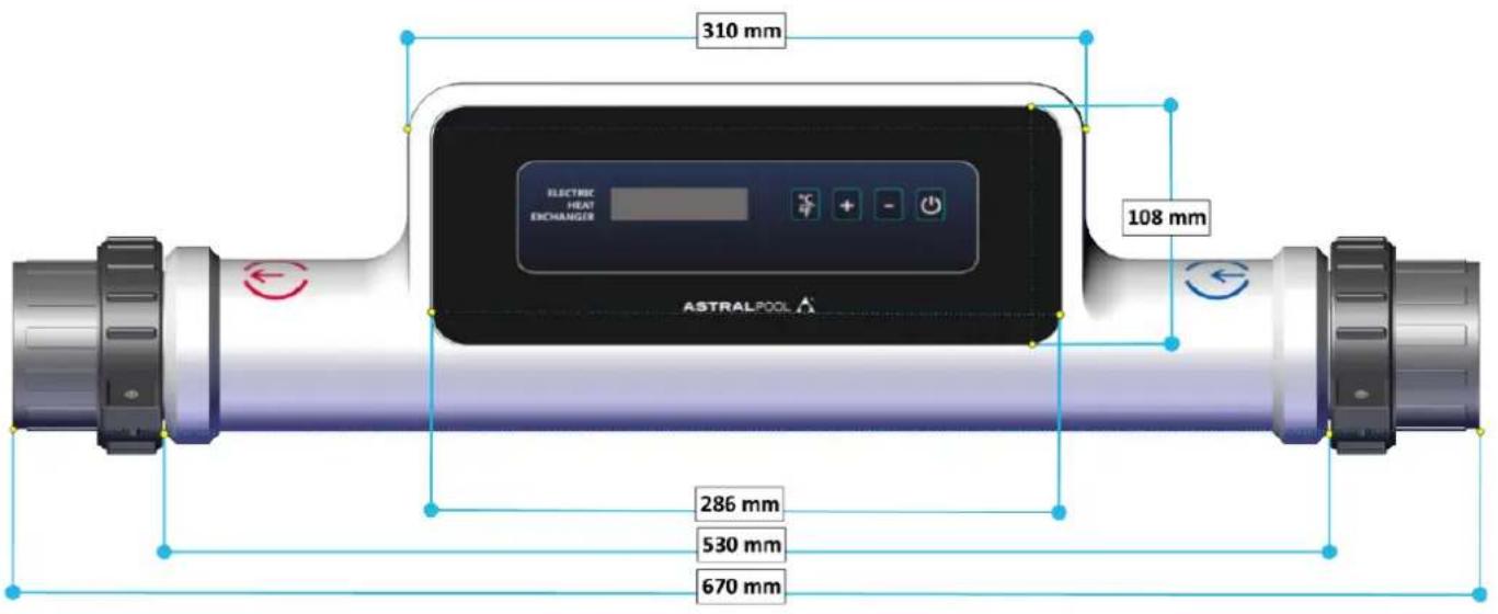
DIMENSIONS / DIMENSIONES / DIMENSIONS
GRÖBE / DIMENSIONI / DIMENSÕES / ΔΙΑΣΤΑΣΕΙΣ
| PART N° | DESCRIPTION | MODEL | CODE | ||||
| 1 | STAINLESS STEEL 316 TUBE TUBO INOXIDABLE 316 TUBE ACIER INOXYDABLE 316ROHR INOX 316 TUBO ACCIAIO INOX 316 TUBO DE AÇO INOXIDAVEL 316 | ALL | 60170R0001 | ||||
| 2 | FRONT COVER TAPA FRONTAL COUVERCLE FRONTALFRONT-DECKEL COPERCHIO DISPLAY TAMPA FRONTAL | ALL | 60170R0002 | ||||
| 3 | DISPLAY PCB TARJETA DISPLAY AFFICHAGE CARTE IMPRIMÉE NON MODBUSDISPLAY-LEITERPLATTE PIASTRINA DISPLAY PLACA DISPLAY MODBUS | 60170R000365321R0001 | |||||
| 4 | DISPLAY COVER TAPA DISPLAYDISPLAY-DECKEL | COUVERCLE DISPLAYCOPERCHIO DISPLAY TAMPA PLACAA DISPLAY | ALL | 60170R0004 | |||
| 5 | REAR COVER RÜCK-DECKEL | TAPA TRASERACOPERCHIO DIDIETRO | COUVERCLE ARRIÈRETAMPA TRASEIRA | ALL | 60170R0005 | ||
| 6 | HEATING ELEMENT | RESISTENCIA ELECTRICA | RÉSISTANCE DE CHAUFFAGE | 3Kw-INC6Kw-INC9Kw-INC12Kw-INC18Kw-INC | 3Kw-TIT6Kw-TIT9Kw-TIT12Kw-TIT18Kw-TIT | 60170R000660171R000160172R000160173R000160174R0001 | 65321R000265322R000165323R000165324R000165325R0001 |
| HEIZELEMENT | RESISTENZA DI RISCALDAMENTO | RESISTENCIA DE AQUECIMENTO | |||||
| 7 | TRIAC TRIAC | TRIAC TRIAC | TRIAC TRIAC | ALL | 60170R0007 | ||
| 8 | TRIAC MOUNTINGSTÜTZE TRIAC | SOPORTE TRIACAPPOGGIO TIRAC | APPUI TRIACSUPORTE TRIAC | ALL | 60170R0008 | ||
| 9 | FLOWSWITCH DURCHFLUSSSCHALTER | FLUJOSTATORIVELATORE DI FLUSSO | DÉTECTERU DE FLUXFLOXOSTATO | ALL | 60170R0009 | ||
| 10 | TEMPERATURE PROBE SONDA TEMPERATUR-SONDE (FÜHLER) | MPERATURA SONDE DE SONDA DI TEMPERATURA | TEMPÉRATURESONDA TEMPERATURA | ALL | 60170R0010 | ||
| 11 | POWER PCB GRUNDLEITERPLATTE | TARJETA POTENCIAPIASTRINA POTENZA | PLAQUE PUISSANCEPLACA POTENCIA | ALL | 60170R0011 | ||
| 12 | CONNECTION CABLES ANSCHLUSSLEITUNGEN | CABLES DE CONEXIONCAVI DI COLLEGAMENTO | CÂBLES DE CONNEXIONCABOS DE CONEXÃO | ALL | 60170R0012 | ||
| 13 | COMMUNICATION BUS KOMMUNIKATIONS-LEITUNGEN | BUS DE COMUNICACIONLINIE DI COMUNICAZIONE | LIGNES DE COMMUNICATIONLINHAS DE COMUNICAÇÃO | ALL | 60170R0013 | ||
| 14 | TERMINALS COVER KLEMMEN-DECKEL COPERCHIO MORSETTO | TAPA BORNASCOPERCHIO MORSETTO TERMINAIS TAMPA | COUVERCLE BORNES | ALL | 60170R0014 | ||
| 15 | MODBUS COVER MODBUS-DECKEL | TAPA MODBUSCOPERCHIO MODBUS TAMPA MODBUS | COUVERCLE MODBUS | ALL | 60170R0015 | ||
| 16 | HALF NUTHALBKLAMMER | TUERCA PARTIDAMEZZA DADO | ECROU DEMIMEIO PORCA | ALL | 60170R0016 | ||
| 17 | GASKET DICHTRING | JUNTAANELLO DI TENUTA | BAGUE D'ÉTANCHÉITÉJUNTA | ALL | 60170R0017 | ||
| 18 | RACORD 63mmANSCHLUSSSTUTZEN 63mm | RACORD 63mmBOCCHETTONE 63mm | RACCORD 63mmRACORD 63mm | ALL | 60170R0018 | ||
| 19 | HOLDING CLAMP STÜTZKLAMMER | GRAPA SOPORTEGANCIO SUPPORTO | SUPPORT-CRAMPONPRENDE BRACADEIRA | ALL | 60170R0019 | ||
| 20 | REDUCING BUSH 63-50mmMINDERUNG 63-50mm | REDUCCION 63-50mm RÉDUCTIONMINORAZIONE 63-50mm | 63-50mmREDUÇAO 63mm | ALL | 60170R0020 | ||
| 21 | CABLE GLAND IP67WANDDURCHFÜHRUNG IP67 | PASAMUROS IP67PASSAMURI IP67 | TRAVERSE À PAROI IP67PASAMUROS IP67 | ALL | 60170R0021 | ||
| 22 | ELECTRICAL LOOM KLEMMEN-UEBERBRUECKUNG | PUENTE DE BORNASCOLLEGAMENTO | LIENCONEXÃO | 3, 6, 9 kW | 60170R0022 | ||
INSTALLATION – INSTALACION – INSTALLAZIONE – INSTALAÇÃO – EΓΚΑΤΑΣΤΑΣΗ
natural_image
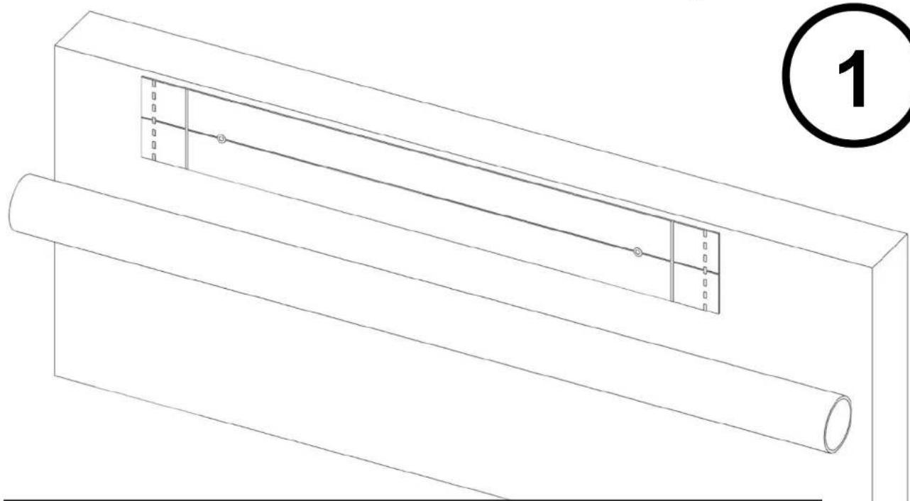
Technical line drawing of a mechanical assembly with two cylindrical components and a central rod, labeled with number 1 (no text or symbols on the diagram itself)- Locate where the heater is to be installed and check the necessary space with the template.
- Localizar dónde se va a instalar el calentador y comprobar que se dispone de espacio suficiente.
- Localiser où l'échangeur s'installera est voir si on a espace suffisant.
- Den Installationsplatz des Wärmetauschers auffindig machen und nachschauen ob noch genug Freiraum vorhanden ist.
- Localizzare dove s'installerà lo scambiatore e comprovare se c'e ancora spazio abbastanza.
- Localizar onde se vai instalar o aquecedor e comprovar que existe espaço suficiente.
- Εντοπίστε πού πρόκειται να εγκατασταθεί ο θερμαντηρας και ελέγξτε τον απαραίτητο χώρο με το πρότυπο.
natural_image
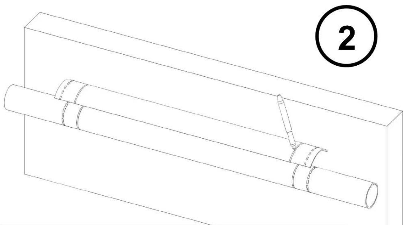
Technical line drawing of a mechanical assembly with two cylindrical components and a pin inserted, labeled with circled number 2 (no text or symbols on the diagram itself)- Mark the pipe the two positions indicated on the template. Cut along the solid line.
- Marcar el tubo las dos posiciones indicadas en la plantilla. Cortar por la línea contínua.
- Marquer le tube les deux positions indiquées dans le patron. Coûter le long de la ligne.
- Das Rohr mit der Schablone auf beiden Seiten markieren. Entlang der Linie schneiden.
- Marcare il tubo le due posizione indicate sulla matrice. Tagliare lungo la linea.
- Marcar no tubo as duas posições indicadas no ecrã. Cortar pela linha contínua.
- Σημειώστε το σωλήνα στις δύο θέσεις που υποδεικνύονται στο πρότυπο. Κόψτε κατά μήκος της συμπαγούς γραμμής.
natural_image
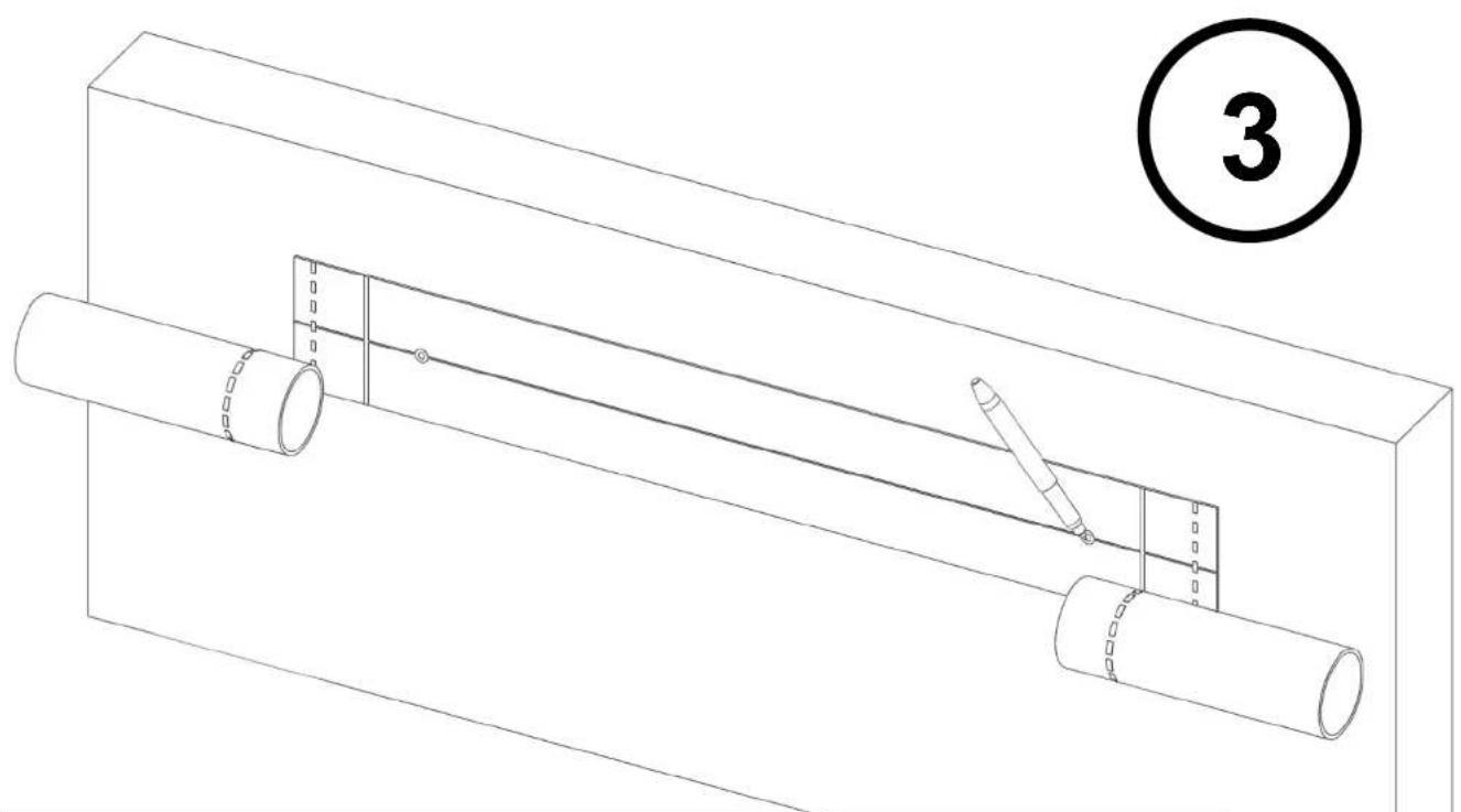
Technical line drawing of a mechanical assembly with two pipes and a tool, no text or symbols present- Place the template on the holding surface and mark the holes position. Drill subsequently.
- Colocar la plantilla en la superficie de apoyo y marcar los agujeros. Taladrar posteriormente.
- Placer le patron sur la surface d'appui est marquer les trous est percer.
• Die Schablone auf der Stützoberfläche anbringen und die Löcher vormarkieren. Danach bohren. - Piazzare la matrice sulla superficie d'appoggio e marcare i buchi. Perforare posteriormente.
- Colocar o modelo na superfície de apoio e marcar os orifícios. Perfurar posteriormente.
- Τοποθετήστε το πρότυπο στην επιφάνεια συγκράτησης και σημειώστε τη θέση των οπών. Τρυπήστε στη συνέχεια.
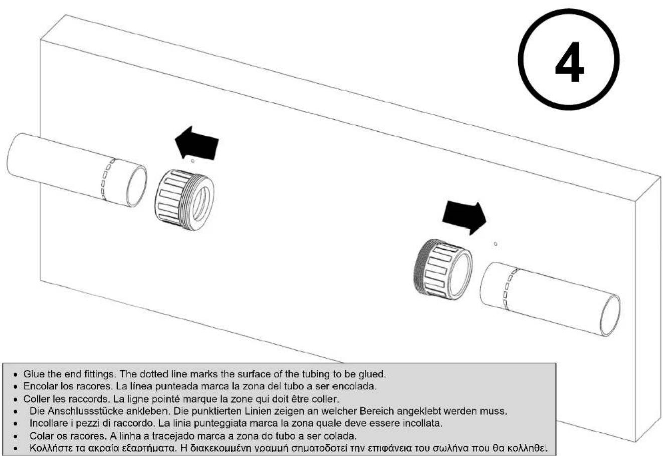
- Glue the end fittings. The dotted line marks the surface of the tubing to be glued.
- Encolar los racores. La línea punteada marca la zona del tubo a ser encolada.
- Coller les raccords. La ligne pointé marque la zone qui doit être coller.
• Die Anschlussstücke ankleben. Die punktierten Linien zeigen an welcher Bereich angeklebt werden muss. - Incollare i pezzi di raccordo. La linia punteggiata marca la zona quale deve essere incollata.
- Colar os racores. A linha a tracejado marca a zona do tubo a ser colada.
• Κολλήστε τα ακραία εξαρτήματα. Η διακεκομμένη γραμμή σηματοδοτεί την επιφάνεια του σωλήνα που θα κολληθεί.
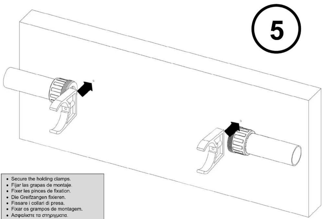
- Secure the holding clamps.
- Fijar las grapas de montaje
- Fixer les pinces de fixation.
• Die Greifzangen fixieren.
• Fissare i collari di presa. - Fixar os grampos de montagem.
• Ασφαλιστε τα στηριγματα.
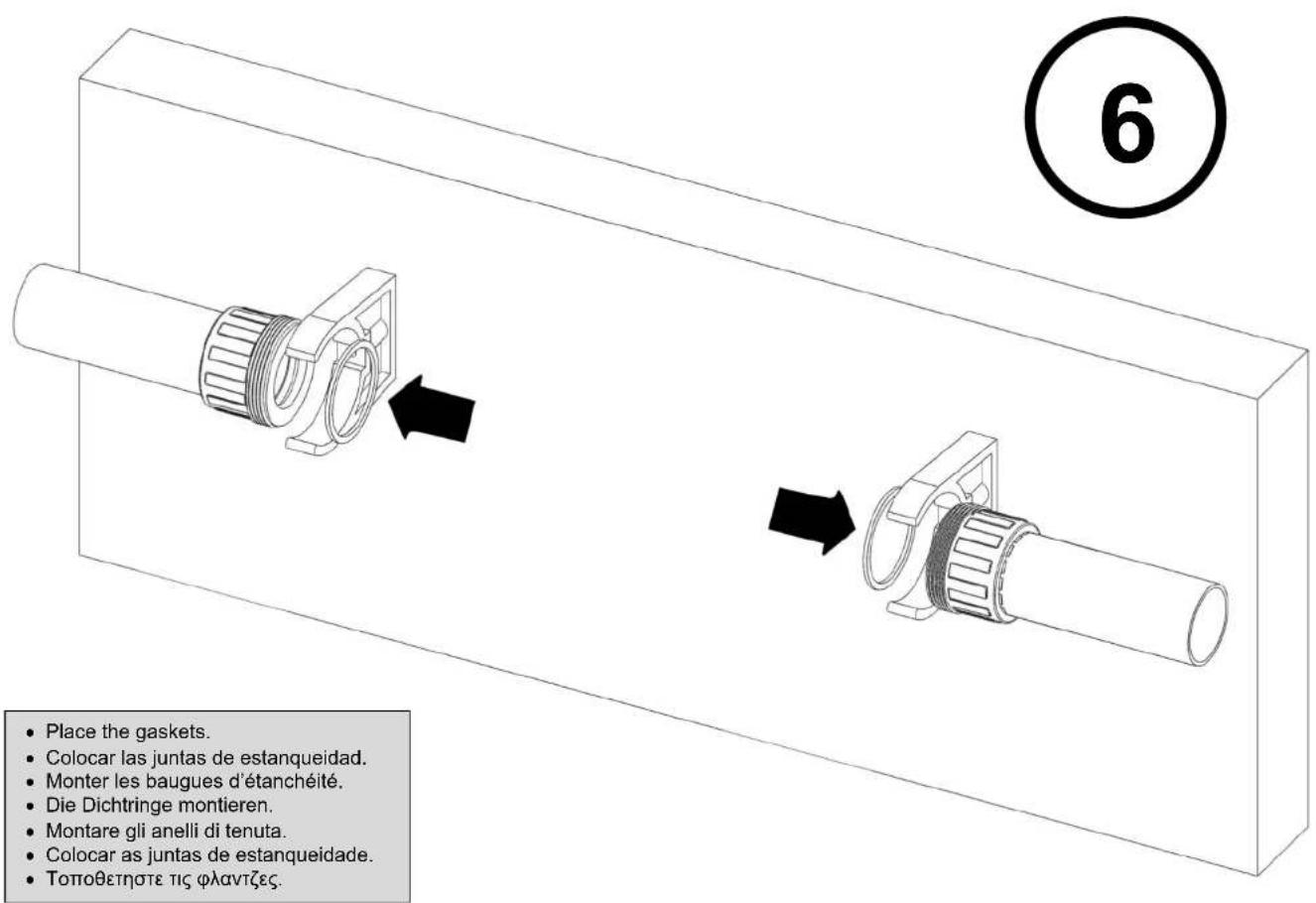
- Place the gaskets
- Colocar las juntas de estanqueidad.
- Monter les baugues d'étanchéité.
• Die Dichtringe montieren.
• Montare gli anelli di tenuta. - Colocar as juntas de estanqueidade.
• Τοποθετηστε τις φλαντζες
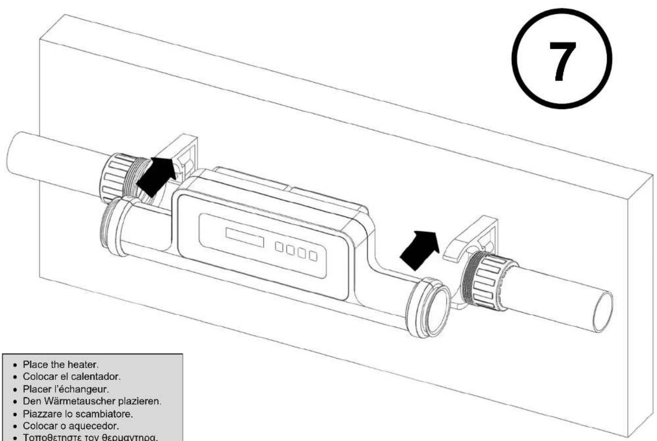
- Place the heater.
- Colocar el calentador.
- Placer l'échangeur.
• Den Wärmetauscher plazieren.
• Piazzare lo scambiatore. - Colocar o aquecedor.
• Τοποθετηστε τον θερμαντηρα.
Place the half nuts.
Declares under their own responsibility that all the heaters: COMPACT® Electricheat Excahanger
Manufactured since 31/07/2015, independent of the serial number, are in compliance with:
Machine safety directive 2006/42/EC.
Electromagnetic compatibility directive 2004/108/EC and its modifications.
Low-voltage equipment directive 2006/95/EC.
Restrictions in the use of certain risky substances in the electrical and electronic instruments 2011/65/EU (RoHS).
Relative to the electrical and electronic waste products 2012/19/UE (RAEE).
Relative to the electrical and electronic instruments and the management of their waste products Spanish R.D. 208/2005 & 219/2013.
The registration, the evaluation, the authorization and the restriction of the chemical substances EC N° 1907/2006 (REACH) and amendment 126/2013 (REACH).
Mr. JMAquiluè, Chief Executive Officer of B-39390968
For further information, please visit - Para más información, por favor, visite - Pour plus d'informations, veuillez visiter - Weitere Informationen finden Sie unter - Per ulteriori informazioni, visitare - Para mais informações, visite:
https://www.astralpool.com/


WE RESERVE THE RIGHT TO CHANGE ALL OR PART OF THE FEATURES OF THE ARTICLES OR CONTENTS OF THIS DOCUMENT, WITHOUT PRIOR NOTICE
NOS RESERVAMOS EL DERECHO DE CAMBIAR TOTAL O PARCIALMENTE LAS CARACTERÍSTICAS DE NUESTROS ARTÍCULOS O CONTENIDO DE ESTE DOCUMENTO SIN PREVIO AVISO.
NOUS NOUS RÉSERVONS LE DROIT DE MODIFIER EN TOUT OU EN PARTIE LES CARACTÉRISTIQUES DE NOS ARTICLES OU LE CONTENU DE CE DOCUMENT SANS AVIS
DE WIR BEHALTEN UNS DAS RECHT VOR, DIE CHARAKTERISTIKA UNSERER PRODUKTE ODER DEN INHALT DIESES DOKUMENTS OHNE VORHERIGE ANKÜNDIGUNG VOLLSTÄNDIG ODER TEILWEISE ZU ÄNDERN.
CI RISERVIAMO IL DIRITTO DI MODIFICARE IN TUTTO O IN PARTE LE CARATTERISTICHE DEI NOSTRI ARTICOLI O CONTENUTO DI QUESTO DOCUMENTO SENZA PREAVVISO.
WIJ BEHOUDEN ONS HET RECHT VOOR OM DE KENMERKEN VAN DE ARTIKELS OF DE INHOUD VAN DIT DOCUMENT ZONDER VOORAF GAANDE KENNISGEVING GEHEEL OF GEDEELTELUK TE WIJZIGEN.
RESERVAMO-NOS O DIREITO DE ALTERAR TOTAL OU PARCIALMENTE AS CARACTERÍSTICAS DOS NOSSOS ARTIGOS OU O CONTEÚDO DESTE DOCUMENTO SEM AVISO PRÉVIO.


- INFORMATION
- WARNING
- PRODUCT DESCRIPTION
- INSTALLATION
- POSITIONING
- ATTENTION
- PIPING DETAILS
- ELECTRICAL CONNECTION
- POWER REQUIREMENTS
- CABLE SECTION
- ELECTRICAL DIAGRAM See image 10.
- FLOW REQUIREMENTS
- WATER QUALITY REQUIREMENTS
- CHANGING DEFAULT FLOW DIRECTION
- START-UP AND OPERATION
- TIME CLOCK
- TROUBLE SHOOTING
- UNIT SCREEN DOES NOT LIGHT UP
- UNIT WORKS INTERMITENTLY
- UNIT IS SWITCHED ON BUT IT IS NOT HEATING WATER
- RCD SWITCHS IMMEDIATELY AFTER POWERING ON THE HEATER
- UNIT IS SWITCHED ON AND WORKING BUT AFTER MANY TIME NO WARMER WATER APPRECIATED
- DISPLAY SHOWS INCORRECT TEMPERATURE: -32°C / -25°F
- MODBUS
- PRODUCT RECYCLING
- WARRANTY CERTIFICATE
- - WARRANTY COVERAGE
- - CONDITIONS TO WARRANTY
- - LIMITATIONS
- TABLA DE CONTENIDOS
- ATENCION
- RECICLAJE DEL PRODUCTO
- RECYCLAGE DU PRODUIT
- ACHTUNG
- SECÇÃO DO CABO
- DIMENSIONS / DIMENSIONES / DIMENSIONS
- GRÖBE / DIMENSIONI / DIMENSÕES / ΔΙΑΣΤΑΣΕΙΣ
- INSTALLATION – INSTALACION – INSTALLAZIONE – INSTALAÇÃO – EΓΚΑΤΑΣΤΑΣΗ
Brand : ASTRALPOOL
Model : Compact ElectricHeat
Category : Swimming Pool