
DIR350R - Electric heater HARVIA - Free user manual and instructions
Find the device manual for free DIR350R HARVIA in PDF.

| Product Type | Full spectrum infrared electric heater |
| Brand | Harvia |
| Model | DIR350R |
| Power | 350 W |
| Power Supply | 230 V ~ 1N 50 Hz |
| Protection Rating | IPX2 |
| Radiation Angle | 122.5° |
| Thermal Fuse | 130 °C |
| Front Material | Dark Schott Nextrema glass |
| Heating Element | Full spectrum Vitae |
| Radiation Distribution | A: 24%, B: 55%, C: 21% |
| Power Cable Length | 3 m with connector |
| Permissible Ambient Temperature | +10 °C to +140 °C |
| Storage Temperature | -25 °C to +70 °C |
| Intended Use | Heating the human body or infrared cabin |
| Possible Installation | Rear, front heater or ceiling |
| Adjustment | Progressive via external control |
| Optional Accessories | Stainless steel front panel, protection grille, ergonomic backrest, etc. |
| Maintenance | Maintenance-free; clean with a damp cloth after cooling |
| Safety | Safety temperature limiter; do not cover; respect minimum distances |
| Protection rating with IPX4 accessory | Possible with front panel or wooden backrest |
Frequently Asked Questions - DIR350R HARVIA
User questions about DIR350R HARVIA
0 question about this device. Answer the ones you know or ask your own.
Ask a new question about this device
Download the instructions for your Electric heater in PDF format for free! Find your manual DIR350R - HARVIA and take your electronic device back in hand. On this page are published all the documents necessary for the use of your device. DIR350R by HARVIA.
USER MANUAL DIR350R HARVIA
Full spectrum radiator
VITAE 350 / 500 / 750 / 1300
ECO 350 / 500 / 750
INSTRUCTIONS FOR INSTALLATION AND USE English
natural_image
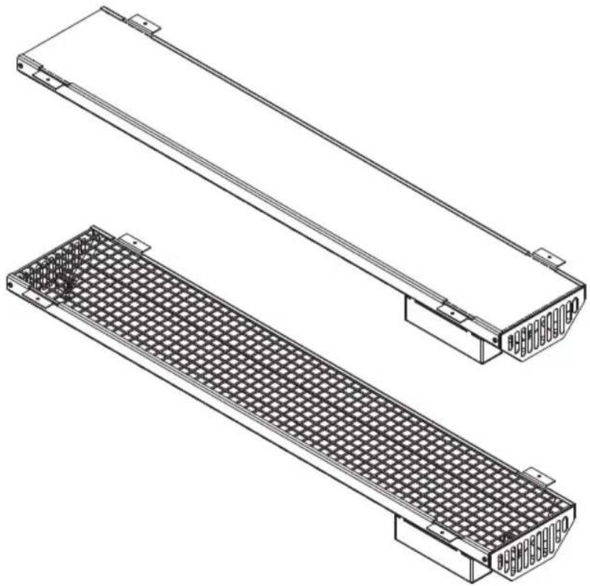
Technical line drawing of two rectangular electronic components with grid patterns, no text or symbols present1-027-780 / DIR-350-R 1-027-845 / WIR-350-R
1-027-781 / DIR-500-R 1-027-846 / WIR-500-R
1-027-782 / DIR-750-R 1-027-847 / WIR-750-R
1-027-779 / DIR-1300-R 1-027-844 / WIR-1300-R
1-027-785 / ECO-350-R 1-027-784 / ECO-300-G
1-027-788 / ECO-500-R 1-027-787 / ECO-500-G
1-027-790 / ECO-750-R
Table of Contents
-
About this instruction manual 3
-
Important information for your safety 4
2.1. Intended use 4
2.2. Safety information 4
- Product description 7
3.1. Scope of delivery 7
3.2. Product features 7
3.3. Optional accessories 7
-
Correct placement 8
-
Installation and connection 9
5.1. Safety distances 10
5.2. Installation cut-out 11
5.3. Recessed 12
- Cleaning and maintenance 13
6.1. Cleaning....13
6.2. Maintenance 13
-
Disposal 13
-
Technical data 14
1. About this instruction manual
Read these assembly instructions carefully and keep them within reach when using the infrared radiator. This ensures that you can refer to information on safety and use at any time.
These installation and operating instructions can also be found in the downloads section of our website: www.sentiotec.com/downloads.
Symbols used for warning notices
These assembly instructions feature warning notices next to activities that present a hazard to the user. Always observe the warning notices. This prevents damage to property and injuries, which in the worst case may be fatal.
The warning notices contain keywords, which have the following meanings:
DANGER!
Serious or fatal injury will occur if this warning notice is not observed.

WARNING!
Serious or fatal injury can occur if this warning notice is not observed.
CAUTION!
Minor injuries can occur if this warning notice is not observed.
ATTENTION!
This keyword is a warning that damage to property can occur.
Other symbols
This symbol indicates tips and useful information.

Do not cover Read the operating instructions

2. Important information for your safety
The infrared radiator has been produced in accordance with the applicable safety rules and regulations. However, hazards may arise during use. Therefore adhere to the following safety information and the specific warning notices in the individual chapters.
2.1. Intended use
The infrared radiator is used to heat people's bodies and/or to heat an infrared cabin.
The infrared radiator may only be operated in combination with a control unit that features an automatic heating time limiter.
Any use exceeding this scope is considered improper use. Improper use can result in damage to the product, severe injuries or death.
2.2. Safety information
- The clamping connections may only be installed by a qualified electrician or similarly qualified person.
-
The plugs connectors may be installed by the user.
-
Installation and connection work on the infrared radiator may only be performed when the power supply is disconnected.
- Also comply with the regulations applicable at the installation location. The specifications in EN 60335-2-53 (VDE 0700 Part 53) must be complied with.
- Ensure that the infrared radiator is not exposed to any mechanical stress, as this will result in breakage. A radiator with a glass front or radiator element that is broken may no longer be used. The glass or the radiator element must be replaced (for the item number, see 8. Technical data on page 14)
- When positioning and installing the infrared radiator, the minimum safety distances must be complied with (see 5.1. Safety distances on page 10)
- The radiator satisfies the requirements in accordance with IPX2. For splashproof installation in accordance with IPX4, the edge of the infrared radiator must be fitted with a veneer (e.g: stainless steel panel, see 3.3. Optional accessories on page 7)
- Radiators must not be installed in a steam bath.
- For your own safety, consult your supplier in the event of problems that are not described in sufficient detail in the user instructions.
- Make sure that no flammable objects have been placed on or suspended in front of the infrared radiator before the control unit is switched on.
- Never touch the glass on the infrared radiator when it is operating. The glass on the infrared radiator becomes very hot. Depending on the user function, contact protection may need to be installed (e.g: wooden backrest, protective grille, see 3.3. Optional accessories on page 7).
- The device must not be used by children under 8 years of age.
- The device may only be used by children over 8 years of age, by persons with limited psychological, sensory or mental capabilities or by persons with lack of experience/knowledge under the following conditions:
– They are supervised.
– They have been shown how to use the device safely and are aware of the hazards that could occur.
- Children must not play with the device.
- Children under 14 years of age may only clean the device if they are supervised.
- If you are affected by a limited sensitivity to heat or are under the influence of alcohol, medication or drugs, refrain from using the infrared radiator for health reasons.
- If persistent erythema (reddening of the skin for more than one day) or mottled skin discolouration occurs after regular exposure to infrared radiation, do not repeat the exposure and consult a doctor to prevent it developing into the more serious condition erythema ab igne.
- It is not advisable to use the infrared radiator within 24 hours of exposing your skin to ultraviolet radiation from an artificial source or from sunbathing.
- If in doubt, people at risk of hyperthermia, such as those who suffer from cardiovascular conditions, should consult a doctor before using a thermal cabin.
- For your own safety, consult your supplier in the event of problems that are not described in sufficient detail in the user instructions.
3. Product description
3.1. Scope of delivery
- IR radiator incl. 3 m connection cable with plug
- Assembly instructions
3.2. Product features
The infrared radiator features the following functions:
- Installation as a back, front or ceiling radiator
- Intrinsically safe due to safety temperature limiter
- Infinitely dimmable
- Models with a glass cover feature protection class IPX4 (suitable for saunas) when installed in combination with front panel or wooden backrest
- VITAE full spectrum radiator Nextrema dark Radiation intensity: A 24%, B 55%, C 21%
- Nextrema full spectrum radiator white Radiation intensity: A 9%, B 57%, C 34%
- ECO full spectrum radiator with glass Radiation intensity: A 24%, B 55%, C 21%
- ECO full spectrum radiator with grille Radiation intensity: A 14%, B 40%, C 46%
3.3. Optional accessories
- Brushed stainless steel front panel (350W/1-027-948, 500/750/1300W/1-027-779)
- Stainless steel front panel painted black (350W/1-027-905, 500/750/1300W/1-027-157)
- Protective grille (350/1-027-791, 500W/1-027-792)
-
Ergonomic backrest (350/500W/514-L/A/D)
• Ergonomic VitaMy backrest (350W/1-039-182) -
Lime wood backrest (350W/1-028-578, 500/750W/1-032-185)
- Prestige wooden backrest (350W/1-032-186, 500/750W/1-032-213)
• Infrared distributor (IR-1P2, IR-1P3, IR-1P5) - Cable for distributor (IR-1P2, IR-1P3, IR-1P5)
- Connection cable for distributor (IR-IS-A03, IR-IS-A10, IR-IS-A25)
4. Correct placement
Application as:
- Back radiator: 350 W, 500 W
- Front radiator: 350 W, 500 W or 750 W
• Ceiling radiator: 750 W, 1300 W
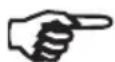
According to EN 60335-2-53, an infrared thermal cabin with a 20cm× 20cm grid of averaged irradiation must not exceed 1000W / m^2 on a person's chest and back (note that this limit relates to the prevention of heat stress).
To ensure that this limit is not exceeded, only a 350 W or 500 W radiator may be used as a back radiator. Furthermore, when positioning the back radiator, ensure that the distance from the person's back to the radiator does not exceed 4 cm.
Only 350 W, 500 W or 750 W radiators may be used as front radiators. Ensure that the minimum distance between the upper body and front radiator is not less than 50 cm (in picture „x“)
To ensure that the ICNIRP limit values for the long-term limit value of 100 W/m ^2 for “infrared eye” are not exceeded, the radiators must be moved down (in picture „Y“).
Detailed information can be found in the appraisals LE-G18/3 and LE-G31/18 conducted by Seibersdorf Laboratories.
5. Installation and connection
WARNING! Danger of electric shock
- Only perform installation and connection work on the infrared radiator when the power supply has been disconnected.
- The radiator is delivered with a plug already installed. The plug-in connector may also be installed by the user.
- If the radiator connection is integrated into a control unit, remove the plug. The clamp connection may only be installed by a qualified electrician or similarly qualified person.
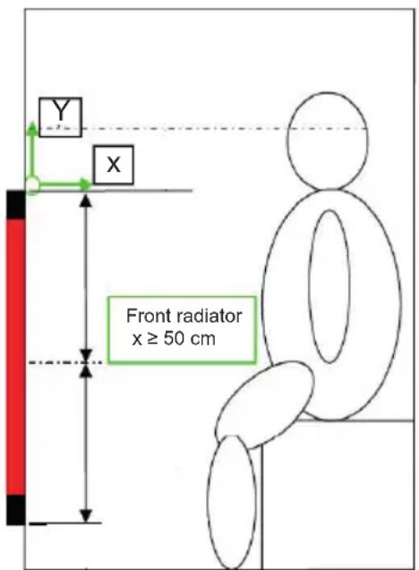
- The rear of the radiator must NOT be covered to ensure that the heat generated can escape through the openings.
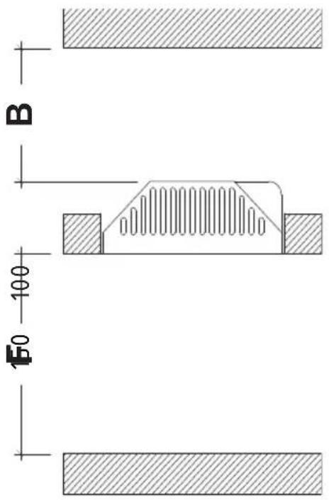
- The ventilation slots at the top and bottom must NOT be covered (see Fig. 1)
- To ensure that the thermal fuse functions correctly, the terminal box for the radiator must be at the top when the radiator is installed vertically (e.g. back radiator) (see Fig. 14).
- Maintain the minimum safety distances to easily flammable materials (see 5.1. Safety distances on page 10).
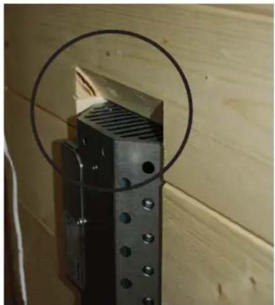
natural_image
Close-up of a black metal bracket mounted on a wooden wall, with a circular ring highlighting the part (no text or symbols visible)
natural_image
Interior view of a room with a metallic wall-mounted device and a black panel, connected by red cables (no visible text or symbols)Fig. 1: Fig. 2: Terminal box positionDo not cover ventilation slots
5.1. Safety distances
Observe the specified minimum safety distances and Fig. 3.
Infrared radiator 350 W, 500 W
(DIR-350-R / DIR-500-R / WE-350-R / WE-500-R /
ECO-350-R / ECO-500-R / ECO-350-G / ECO-500-G)
When installed vertically: When installed horizontally:
B = 15 mm
B = 80 mm
F = 25 ~mm
F = 25 ~mm
Infrared radiator 750 W (DIR-750-R / WIR-750-R / ECO-750-R)
When installed horizontally:
B = 100 mm
F = 150 ~mm
Infrared radiator 1300 W (DIR-1300-R / WIR-1300-R)
When installed horizontally:
B = 150 mm
F = 200 ~mm
Fig. 3: Infrared radiator safety distances
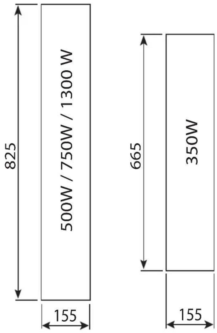
5.2. Installation cut-out
Please note Fig. 1 and Fig. 4.
Fig. 4: Infrared radiator installation cut-outs
Dimensions in mm
other
| Section | Dimension (W) | | ------- | ------------- | | Left | 500 | | Right | 350 | | Total | 155 | | Top Left| 825 | | Top Right| 665 |5.3. Recessed
Please note Fig. 2 and Fig. 5.
CAUTION!
Make sure that the terminal box for the radiator is on top!
An intumescent strip is included with the 1300 W infrared radiator. Stick this to the outer edge of the cut-out before installing the radiator (see A in Fig. 5)
Fig. 5: Installation of infrared radiators without and with optional stainless steel panel
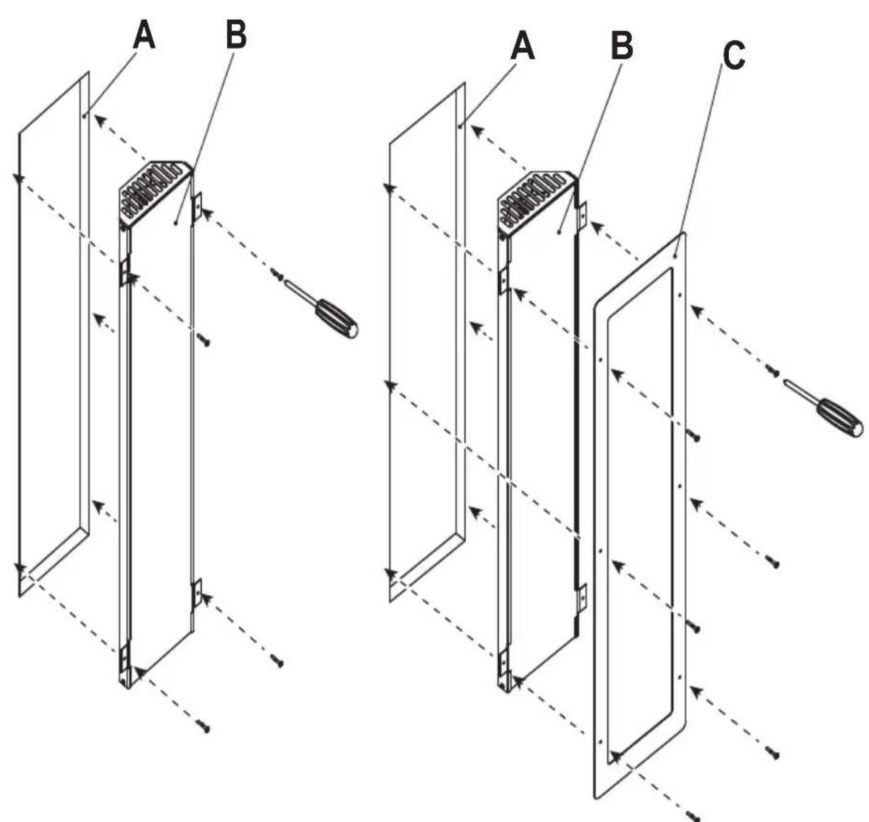
A Cabin wall cut-out
B Infrared radiator
C Stainless steel panel (optional)
6. Cleaning and maintenance
6.1. Cleaning
ATTENTION!
Damage to the unit
The infrared radiator is protected against splashing water, however direct contact with water could still damage it.
- NEVER immerse the device in water.
- Do not pour water over the device.
-
Do not get the device too wet when cleaning it.
-
Switch off the radiator
- Allow the radiator to cool down
- Carefully wipe down the glass with a damp cloth.
6.2. Maintenance
The infrared radiator is maintenance-free.
7. Disposal
- Dispose of packaging materials in accordance with the applicable waste disposal regulations.
- Used devices contain reusable materials as well as hazardous substances. Therefore, do not dispose of your used device with household waste, but do so in accordance with the locally applicable regulations.
8. Technical data
General, for all radiators
Storage conditions: -25^ to +70^
Ambient temperature: +10°C to +140°C
Mains voltage: 230 V \~ 1N 50 Hz
Thermal fuse: 130°C
IP code: IPX2
Connection cable: 3 m - 3 x 1.5 mm² insulated with plug
Radiation angle: 122.5°
8
2
686 818
6
150
178
DIR-350-R
Dimensions: L1 = 523 mm, L2 = 658 mm
Front glass: Schott Nextrema, dark (1-027-840)
Radiator element: 350 W - Vitae (1-027-836)
DIR-500-R
Dimensions: L1 = 686 mm, L2 = 818 mm
Front glass: Schott Nextrema, dark (1-027-839)
Radiator element: 500 W - Vitae (1-027-837)
DIR-750-R
Dimensions: L1 = 686 mm, L2 = 818 mm
Front glass: Schott Nextrema, dark (1-027-839)
Radiator element: 750 W - Vitae (1-027-838)
DIR-1300-R
Dimensions: L1 = 686 mm, L2 = 818 mm
Front glass: Schott Nextrema, dark (1-027-839)
Radiator element: 1300 W - Vitae (1-027-835)
WIR-350-R
Dimensions: L1 = 523 mm, L2 = 658 mm
Front glass: Schott Nextrema, white (1-027-842)
Radiator element: 350 W - ECO full spectrum (1-027-783)
WIR-500-R
Dimensions: L1 = 686 mm, L2 = 818 mm
Front glass: Schott Nextrema, white (1-027-841)
Radiator element: 500 W - ECO full spectrum (1-027-786)
WIR-750-R
Dimensions: L1 = 686 mm, L2 = 818 mm
Front glass: Schott Nextrema, white (1-027-841)
Radiator element: 750 W - ECO full spectrum (1-027-789)
WIR-1300-R
Dimensions: L1 = 686 mm, L2 = 818 mm
Front glass: Schott Nextrema, white (1-027-841)
Radiator element: 1300 W - Vitae (1-027-835)
ECO-350-R
Dimensions: L1 = 523 mm, L2 = 658 mm
Front glass: Glass ceramic, dark (1-030-968)
Radiator element: 350 W - ECO full spectrum (1-027-783)
ECO-500-R
Dimensions: L1 = 686 mm, L2 = 818 mm
Front glass: Glass ceramic, dark (1-030-969)
Radiator element: 500 W - ECO full spectrum (1-027-786)
ECO-750-R
Dimensions: L1 = 686 mm, L2 = 818 mm
Front glass: Glass ceramic, dark (1-030-969)
Radiator element: 750 W - ECO full spectrum (1-027-789)
ECO-350-G
Dimensions: L1 = 523 mm, L2 = 658 mm
Front: Metal grille, black fibre coated (1-027-791)
Radiator element: 350 W - ECO full spectrum (1-027-783)
ECO-500-G
Dimensions: L1 = 686 mm, L2 = 818 mm
Front: Metal grille, black fibre coated (1-027-792)
Radiator element: 500 W - ECO full spectrum (1-027-786)
natural_image
Technical line drawing of two rectangular electronic components with grid patterns, no text or symbols present1-027-780 / DIR-350-R 1-027-845 / WIR-350-R
1-027-781 / DIR-500-R 1-027-846 / WIR-500-R
1-027-782 / DIR-750-R 1-027-847 / WIR-750-R
1-027-779 / DIR-1300-R 1-027-844 / WIR-1300-R
1-027-785 / ECO-350-R 1-027-784 / ECO-300-G
1-027-788 / ECO-500-R 1-027-787 / ECO-500-G
1-027-790 / ECO-750-R
DE
Inhaltsverzeichnis
natural_image
Close-up of a black metal bracket mounted on a wooden surface, with a circular highlight highlighting the part (no text or symbols visible)Abb. 1: Abburges Bötslitten freilassen

natural_image
Interior view of a room with a metallic wall-mounted panel and red cable, no visible text or symbolsAnschlusskasten
natural_image
Technical line drawing of two rectangular electronic components with grid patterns, no text or symbols present1-027-780 / DIR-350-R 1-027-845 / WIR-350-R
1-027-781 / DIR-500-R 1-027-846 / WIR-500-R
1-027-782 / DIR-750-R 1-027-847 / WIR-750-R
1-027-779 / DIR-1300-R 1-027-844 / WIR-1300-R
1-027-785 / ECO-350-R 1-027-784 / ECO-300-G
1-027-788 / ECO-500-R 1-027-787 / ECO-500-G
1-027-790/ECO-750-R
FR
Table des matières
-
Placement correct 8
-
Montage et raccordement 9
4. Placement correct
natural_image
Close-up of a black metal bracket mounted on a wooden wall, with a circular highlight highlighting the corner detail (no text or symbols visible)natural_image
Interior view of a room with a metallic wall-mounted panel and red cable, no visible text or symbolsde raccordement
Dimensions : L1 = 523 mm, L2 = 658 mm
Dimensions : L1 = 686 mm, L2 = 818 mm
Dimensions : L1 = 686 mm, L2 = 818 mm
Dimensions : L1 = 686 mm, L2 = 818 mm
Dimensions : L1 = 523 mm, L2 = 658 mm
Dimensions : L1 = 686 mm, L2 = 818 mm
Dimensions : L1 = 686 mm, L2 = 818 mm
Dimensions : L1 = 686 mm, L2 = 818 mm
Dimensions : L1 = 523 mm, L2 = 658 mm
Dimensions : L1 = 686 mm, L2 = 818 mm
Dimensions : L1 = 686 mm, L2 = 818 mm
Dimensions : L1 = 523 mm, L2 = 658 mm
Dimensions : L1 = 686 mm, L2 = 818 mm
natural_image
Technical line drawing of two rectangular electronic components with grid patterns, no text or symbols present1-027-780 / DIR-350-R 1-027-845 / WIR-350-R
1-027-781 / DIR-500-R 1-027-846 / WIR-500-R
1-027-782 / DIR-750-R 1-027-847 / WIR-750-R
1-027-779 / DIR-1300-R 1-027-844 / WIR-1300-R
1-027-785 / ECO-350-R 1-027-784 / ECO-300-G
1-027-788 / ECO-500-R 1-027-787 / ECO-500-G
1-027-790 / ECO-750-R
Indice
natural_image
Close-up of a black metal bracket mounted on a wooden wall, with a circular highlight highlighting the part (no text or symbols visible)natural_image
Interior view of a room with a metallic wall-mounted panel and red cable, no visible text or symbolsother
| Section | Width (W) | | ------- | --------- | | Left | 825 | | Right | 665 | | Bottom | 155 |5.3. Installazione
Osservare Fig. 2 e Fig. 5.
ATTENZIONE!
natural_image
Technical line drawing of two rectangular electronic components with grid patterns, no text or symbols present1-027-780 / DIR-350-R 1-027-845 / WIR-350-R
1-027-781 / DIR-500-R 1-027-846 / WIR-500-R
1-027-782 / DIR-750-R 1-027-847 / WIR-750-R
1-027-779 / DIR-1300-R 1-027-844 / WIR-1300-R
1-027-785 / ECO-350-R 1-027-784 / ECO-300-G
1-027-788 / ECO-500-R 1-027-787 / ECO-500-G
1-027-790 / ECO-750-R
NL
Inhoudsopgave
natural_image
Close-up of a black metal bracket with perforated holes and a circular target overlay, mounted on a wooden wall (no text or symbols visible)natural_image
Interior view of a room with a metallic wall-mounted panel and red cable, no visible text or symbolsother
| Dimension | Value | | :--- | :--- | | Width | 825 | | Height | 155 | | Width (Width) | 500W / 750W / 1300 W | The label '500W / 750W / 1300 W' is displayed in the central section of the rectangle.
NL
5.3. Inbouw
natural_image
Technical line drawing of two rectangular electronic components with grid patterns, no text or symbols present1-027-780 / DIR-350-R 1-027-845 / WIR-350-R
1-027-781 / DIR-500-R 1-027-846 / WIR-500-R
1-027-782 / DIR-750-R 1-027-847 / WIR-750-R
1-027-779 / DIR-1300-R 1-027-844 / WIR-1300-R
1-027-785 / ECO-350-R 1-027-784 / ECO-300-G
1-027-788 / ECO-500-R 1-027-787 / ECO-500-G
1-027-790 / ECO-750-R
Obsah
natural_image
Close-up of a metal bracket with perforated holes and a circular target overlay (no text or symbols)natural_image
Interior view of a room with a metallic wall-mounted panel and red cable, no visible text or symbolskrabice

other
| Dimension | Value | | :--- | :--- | | Width | 825 | | Height | 155 | | Width (Width) | 500W / 750W / 1300 W | The label '500W / 750W / 1300 W' is displayed in the central section of the rectangle.
CS
5.3. Montáž
Respektujte Obr. 2 a Obr. 5.
OPATRNĚ!
natural_image
Technical line drawing of two rectangular electronic components with grid patterns, no text or symbols present1-027-780 / DIR-350-R 1-027-845 / WIR-350-R
1-027-781 / DIR-500-R 1-027-846 / WIR-500-R
1-027-782 / DIR-750-R 1-027-847 / WIR-750-R
1-027-779 / DIR-1300-R 1-027-844 / WIR-1300-R
1-027-785 / ECO-350-R 1-027-784 / ECO-300-G
1-027-788 / ECO-500-R 1-027-787 / ECO-500-G
1-027-790 / ECO-750-R
PL
SPIS TREŚCI
natural_image
Close-up of a black electrical outlet mounted on a wooden wall, with a circular highlight highlighting the corner detail (no text or symbols visible)natural_image
Interior view of a room with wooden panel and metal wall-mounted components, no visible text or symbolsprzyłączowej
other
| Dimension | Value | | :--- | :--- | | Width | 825 | | Height | 155 | | Width (Width) | 500W / 750W / 1300 W | The label '500W / 750W / 1300 W' is displayed in the central section of the rectangle.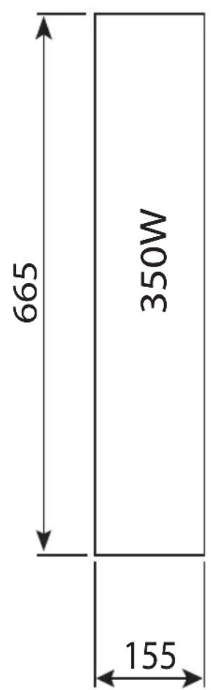
PL
5.3. Montaż
Wymiary: L1 = 523 mm, L2 = 658 mm
Wymiary: L1 = 686 mm, L2 = 818 mm
Wymiary: L1 = 686 mm, L2 = 818 mm
Wymiary: L1 = 686 mm, L2 = 818 mm
Wymiary: L1 = 523 mm, L2 = 658 mm
Wymiary: L1 = 686 mm, L2 = 818 mm
Wymiary: L1 = 686 mm, L2 = 818 mm
Wymiary: L1 = 686 mm, L2 = 818 mm
Wymiary: L1 = 523 mm, L2 = 658 mm
Wymiary: L1 = 686 mm, L2 = 818 mm
Wymiary: L1 = 686 mm, L2 = 818 mm
Wymiary: L1 = 523 mm, L2 = 658 mm
Wymiary: L1 = 686 mm, L2 = 818 mm
natural_image
Technical line drawing of two rectangular electronic components with grid patterns, no text or symbols present1-027-780 / DIR-350-R 1-027-845 / WIR-350-R
1-027-781 / DIR-500-R 1-027-846 / WIR-500-R
1-027-782 / DIR-750-R 1-027-847 / WIR-750-R
1-027-779 / DIR-1300-R 1-027-844 / WIR-1300-R
1-027-785 / ECO-350-R 1-027-784 / ECO-300-G
1-027-788 / ECO-500-R 1-027-787 / ECO-500-G
1-027-790/ECO-750-R
PT
Índice
natural_image
Close-up of a black metal bracket mounted on a wooden wall, with a circular highlight highlighting the corner detail (no text or symbols visible)natural_image
Interior view of a room with a metallic vertical panel and black panel, connected by red cables (no visible text or symbols)de ligação
other
| Dimension | Value | | --------- | ----- | | Top Section | 500W / 750W / 1300W | | Middle Section | 665 | | Bottom Section | 350W | | Total Length | 825 | | Width (Width) | 155 | | Width (Width) | 155 | The labels for the segments are '500W / 750W / 1300W' and '350W'. The width values are explicitly labeled as '665'.5.3. Montagem
Observe a Fig. 2 e Fig. 5.

CUIDADO!
natural_image
Technical line drawing of two rectangular electronic components with grid patterns, no text or symbols present1-027-780 / DIR-350-R 1-027-845 / WIR-350-R
1-027-781 / DIR-500-R 1-027-846 / WIR-500-R
1-027-782 / DIR-750-R 1-027-847 / WIR-750-R
1-027-779 / DIR-1300-R 1-027-844 / WIR-1300-R
1-027-785 / ECO-350-R 1-027-784 / ECO-300-G
1-027-788 / ECO-500-R 1-027-787 / ECO-500-G
1-027-790/ECO-750-R
SV
natural_image
Close-up of a metal bracket with perforated holes and a circular target overlay (no text or symbols visible)natural_image
Interior view of a room with a metallic wall-mounted device and a black panel, no visible text or symbols.Anslutningsläda
5.1. Säkerhetsavständ
other
| Dimension | Value | | :--- | :--- | | Width | 825 | | Height | 155 | | Width (Width) | 500W / 750W / 1300 W | The label '500W / 750W / 1300 W' is displayed in the central section of the rectangle.
5.3. Installation
natural_image
Technical line drawing of two rectangular electronic components with grid patterns, no text or symbols present1-027-780 / DIR-350-R 1-027-845 / WIR-350-R
1-027-781 / DIR-500-R 1-027-846 / WIR-500-R
1-027-782 / DIR-750-R 1-027-847 / WIR-750-R
1-027-779 / DIR-1300-R 1-027-844 / WIR-1300-R
1-027-785 / ECO-350-R 1-027-784 / ECO-300-G
1-027-788 / ECO-500-R 1-027-787 / ECO-500-G
1-027-790 / ECO-750-R
FI
Sisällys
natural_image
Close-up of a black metal bracket mounted on a wooden wall, with a circular highlight highlighting the part (no text or symbols visible)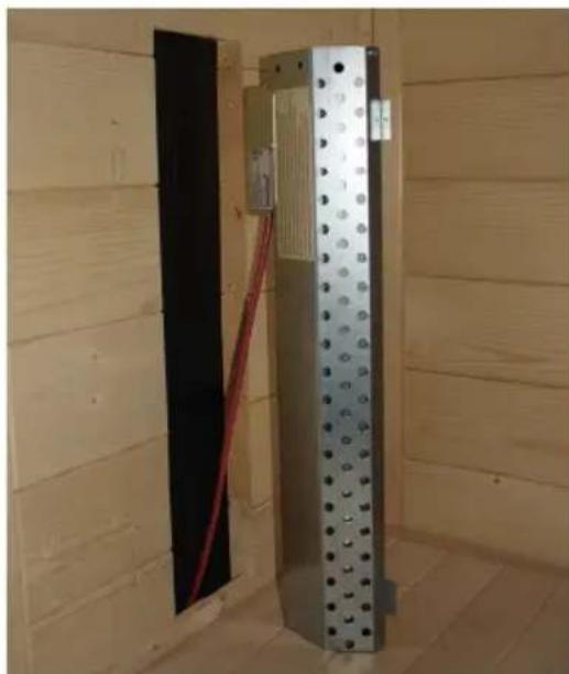
natural_image
Interior view of a room with a metallic wall-mounted device and red cable, no visible text or symbolsnatural_image
Technical line drawing of two rectangular electronic components with grid patterns, no text or symbols present1-027-780/DIR-350-R
1-027-781/DIR-500-R
1-027-782/DIR-750-R
1-027-779/DIR-1300-R
1-027-785/ECO-350-R
1-027-788/ECO-500-R
1-027-790 / ECO-750-R
1-027-845/WIR-350-R
1-027-846/WIR-500-R
1-027-847/WIR-750-R
1-027-844/WIR-1300-R
1-027-784/ECO-300-G
1-027-787/ECO-500-G
RU
Содержание
natural_image
Close-up of a black metal bracket mounted on a wooden wall, with a circular highlight highlighting the mounting detail (no text or symbols visible)natural_image
Interior view of a room with a metallic wall-mounted device and red cable, no visible text or symbols
- Full spectrum radiator
- VITAE 350 / 500 / 750 / 1300
- ECO 350 / 500 / 750
- INSTRUCTIONS FOR INSTALLATION AND USE English
- Table of Contents
- About this instruction manual
- Symbols used for warning notices
- DANGER!
- WARNING!
- CAUTION!
- ATTENTION!
- Other symbols
- Important information for your safety
- Intended use
- Safety information
- Product description
- Scope of delivery
- Product features
- Optional accessories
- Correct placement
- Application as:
- Installation and connection
- WARNING! Danger of electric shock
- Safety distances
- Infrared radiator 350 W, 500 W
- Installation cut-out
- Recessed
- Cleaning and maintenance
- Cleaning
- Damage to the unit
- Maintenance
- Disposal
- Technical data
- General, for all radiators
- DIR-350-R
- DIR-500-R
- DIR-750-R
- DIR-1300-R
- WIR-350-R
- WIR-500-R
- WIR-750-R
- WIR-1300-R
- ECO-350-R
- ECO-500-R
- ECO-750-R
- ECO-350-G
- ECO-500-G
- Inhaltsverzeichnis
- Table des matières
- Placement correct
- Indice
- Installazione
- ATTENZIONE!
- Inhoudsopgave
- Inbouw
- Obsah
- Montáž
- OPATRNĚ!
- SPIS TREŚCI
- Montaż
- Índice
- Montagem
- CUIDADO!
- Säkerhetsavständ
- Installation
- Sisällys
- Содержание
Brand : HARVIA
Model : DIR350R
Category : Electric heater