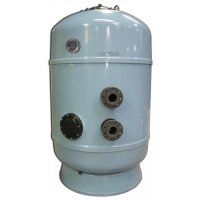
Delta - Water filter ASTRALPOOL - Free user manual and instructions
Find the device manual for free Delta ASTRALPOOL in PDF.



| Product type | Sand water filter with collectors or strainers |
| Brand | AstralPool |
| Model | Delta |
| Body material | Fiberglass reinforced polyester resin |
| Internal material | PVC and PP (collectors, diffusers) |
| Maximum working pressure | Refer to filter nameplate |
| Recommended filtration speed | Up to 40 m³/h/m² |
| Backwash speed | 40-60 m³/h/m² depending on collection system |
| Operation cycles | Filtration, backwash (water and air), rinse, drain, closed |
| Valve type | 4 or 5 valve manifold or multiport valve |
| Air purge | Manual at the top |
| Water drain | Manual at the bottom |
| Pressure gauge | Included for differential pressure monitoring |
| Filter media | Sand (appropriate grain size) |
| Recommended installation | Below pool water level, on a horizontal surface, with clearance all around |
| Maintenance | Periodic backwash, external water cleaning, winter draining |
| Safety | Never operate valves while pump is running; do not exceed maximum pressure |
| Spare parts | Collector arms, strainers, diffusers, purges, gaskets, pressure gauge |
| Warranty | Test certificate and warranty included |
Frequently Asked Questions - Delta ASTRALPOOL
User questions about Delta ASTRALPOOL
0 question about this device. Answer the ones you know or ask your own.
Ask a new question about this device
Download the instructions for your Water filter in PDF format for free! Find your manual Delta - ASTRALPOOL and take your electronic device back in hand. On this page are published all the documents necessary for the use of your device. Delta by ASTRALPOOL.
USER MANUAL Delta ASTRALPOOL
SAND FILTERS FILTRES À SABLE FILTROS DE ARENA FILTRI DI SABBIA SANDFILTER FILTROS DE AREIA FILTRY Z PIASKU – I
natural_image
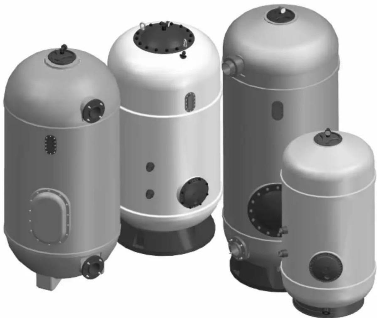
Four identical industrial pressure vessel designs with circular and rectangular features, shown from different angles (no text or symbols visible)INSTRUCTIONS AND OPERATION MANUAL MANUAL D'INSTRUCTIONS ET DE FONCTIONNEMENT MANUAL DE INSTRUCCIONES Y FUNCIONAMIENTO MANUALE DI ISTRUZIONI E FUNZIONAMENTO ANWEISUNGEN- UND OPERATIONSHANDBUCH MANUAL DE INSTRUÇÕES E FUNCIONAMENTO INSTRUKCJA OBSŁUGI I DZIAŁANIA
IMPORTANT: The instruction manual that you have in your hands contains fundamental information on the necessary security measures which need to be adhered to when installing and commissioning the filter. It is therefore essential that both the installation engineer and the end user read these instructions before proceeding any further.
"In order to archive optimum performance from your filter, please see the following instructions".
1. CHECK THE PACKAGING
Check that the filter and all its components are in good condition after transportation.
There is a box with the filter, which contains pressure gauges, along with other accessories. There will also be a guarantee and test certificate.
2. GENERAL SPECIFICATIONS
Filters are the most important part of a water filtration system, and their function is to remove suspended solids and clarify the water.
The effect of correct filtration will influence the results of disinfectant process.
The principle of filtration involves retaining the suspended particles that the water tries to carry with it through the filter sand bed.
The water treatment process involves a range of equipment besides filters, such as; pumps, chemical dosing, pool shell fittings, which ensure the correct suction and return of water, which with the rest of the equipment ensures the correct circulation and maintenance of the water quality.
Whilst standards are approaching homologation throughout Europe, each country normally has its own standards, regulations or recommendations governing private and public pools, and installers should adhere to these when designing and installing any system. All designs and all materials used must meet the relevant standards.
The filtration quality may depend on different factors: Design of the filter, type of collector used - collectors or nozzles, media bed depth, specifications and density of the filtering material, etc. At the same time the filtration velocity is a determining factor when seeking good quality filtration and a velocity of no more than 40 m/h is recommended.
Filters are manufactured from polyester resin and glass fibre materials, which have excellent anticorrosive properties. The interior includes a collector and diffuser made from PVC and PP plastic. They are also resistant to salt water.
The special layer of isophthalic resin on the interior of the filter gives it maximum durability against wear and tear and abrasion. Filters may also manufactured on request with a lining, wich is resistant to most chemicals including ozone.
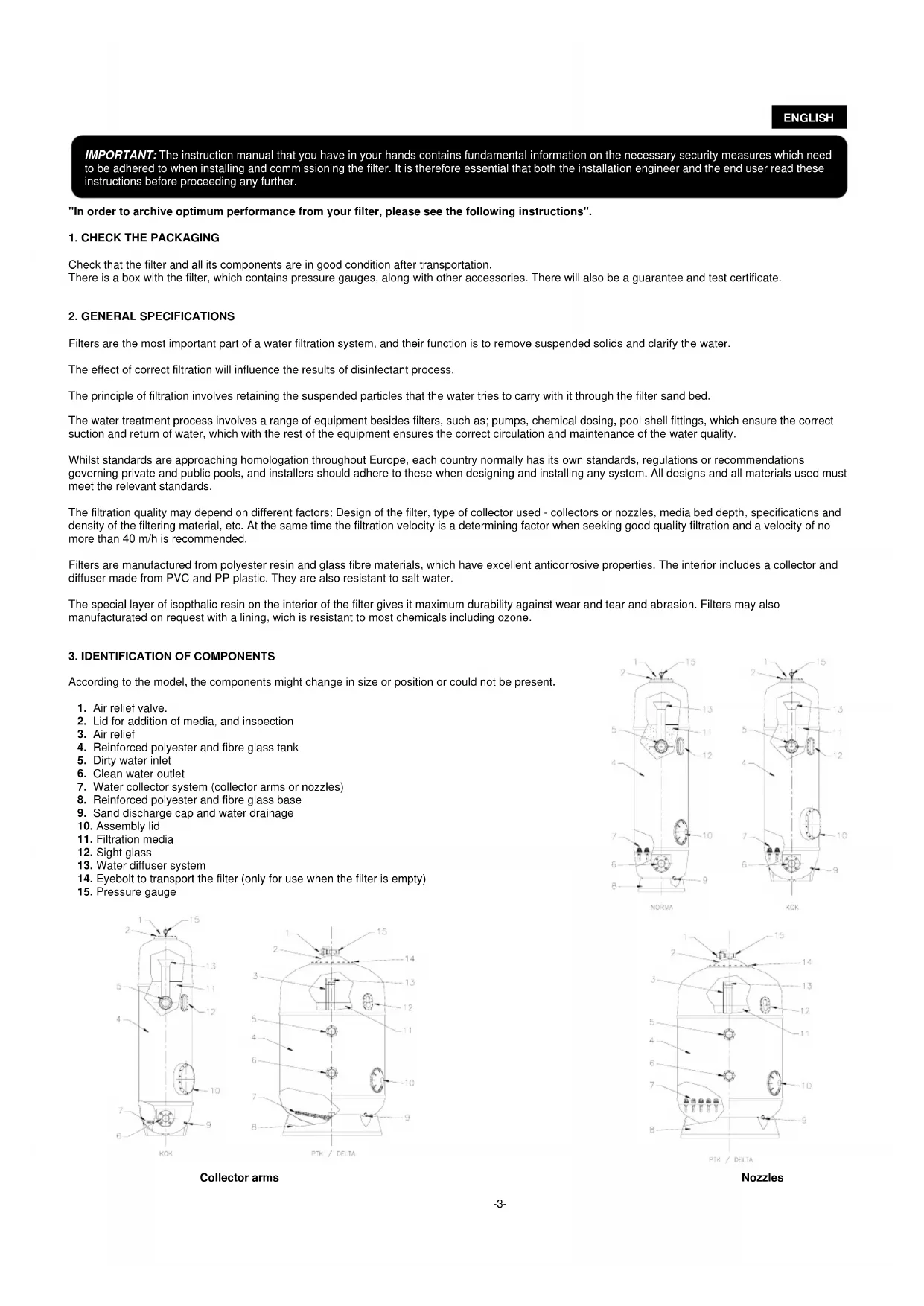
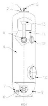
3. IDENTIFICATION OF COMPONENTS
According to the model, the components might change in size or position or could not be present.
- Air relief valve.
- Lid for addition of media, and inspection
- Air relief
- Reinforced polyester and fibre glass tank
- Dirty water inlet
- Clean water outlet
- Water collector system (collector arms or nozzles)
- Reinforced polyester and fibre glass base
- Sand discharge cap and water drainage
- Assembly lid
- Filtration media
- Sight glass
- Water diffuser system
- Eyebolt to transport the filter (only for use when the filter is empty)
- Pressure gauge
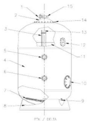
Collector arms
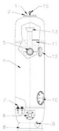
NORVA
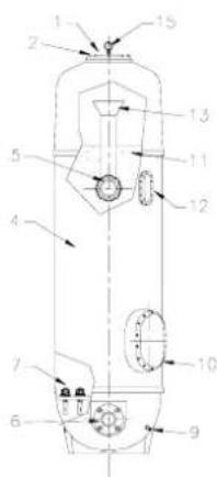
XOK
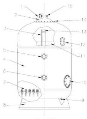
PTK / DELTA
Nozzles
ENGLISH
4. IDENTIFICATION OF COMPONENTS
In order to achieve successful installation it is important to consider the following points:
- In order to backwash the filter, the system of pumps and filters must combine to obtain the necessary flow, which can be from 40 - 50m/h lateral models, and up to 60 m/h for nozzle plate models.
- To scour the filter with air (nozzle plate models or models with double laterals) it will use one or more air blower or capable of supplying air at a velocity of 60 m/h at 300 mbar. Never use a compressor because damage could occur due to excessive pressure.
- It is advised to install the filters below the level of, and as close to the pool as possible.
- The plant room where the filters are installed should be well ventilated and have the necessary drainage channels available to allow escape of water, should a pipe, filter or pump leak in the case of an accident, preventing damage to any equipment. If it is not possible to install such drainage measures, then an alternative automated system (e.g. submersible pumps) should be installed for water removal.
5. INSTALLATION
Filters are delivered packaged and palleted, due to their weight and volume. This can make them difficult to manoeuvre around the building site and to install therefore it is recommended to transport them by fork lift, crane etc.
Filters are made of plastic, and although they are designed to resist internal pressure, they can be susceptible to external damage. It is important to ensure that the filter does not receive any external knocks during installation or operation that could damage the base, the tank or any connections.
Always use suitable plastic connections and ensure they are fitted with suitable supports and are not forced, or under stress.
The media must only be loaded once the filter is placed in its final position, following the instructions stated at the "Starting up" paragraph.
Filters, like other items of the facility, will need regular checks, so it is essential to leave a suitable working clearance above and around the filter. (Fig. 1)
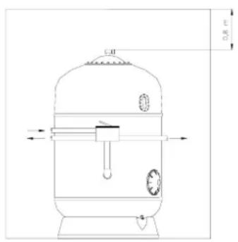
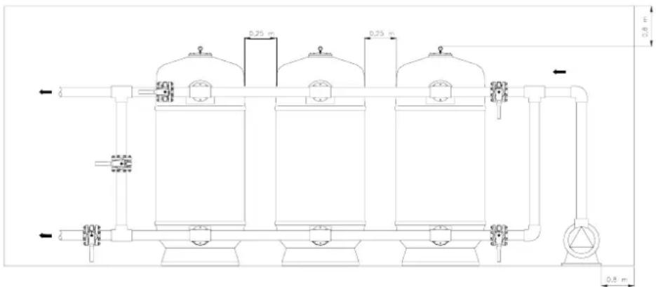
Fig. 1
Correct installation of the filters:
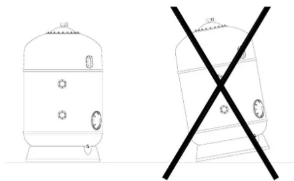
- Place the filters in their designated position, and ensure that they are stable and the floor is perfectly flat. (Fig. 2)
- Assemble the valves on the filters, ensuring they are not stressed. Remember that the water-tightness of the unions is achieved with seals and gaskets, so do not over tighten the bolts. Do not use Teflon (PTFE) tape.
• Install adequate battery/pipe supports and adjust their height accordingly. - Connect the valves to the pump discharge pipes, the return pipes to the pool and to the waste drain.
natural_image
Two technical line drawings of industrial tanks with circular components, one marked with a cross symbol (no text or labels present)Fig. 2
5.1 INSTALLATION OF THE PRESSURE GAUGES (Fig 3)
It is recommended to install a pressure gauge at the filter outlet.
The pressure gauges indicate when it is necessary to backwash the filter. For example, in a clean filter the entrance pressure should be between 0,8 and 1 kg/cm ^2 and the outlet pressure should be between 0,4 and 0,6 kg/cm ^2 .
When the pressure difference between the inlet and the outlet is higher than 0.8kg/cm^2 , then it is time to backwash the filter.
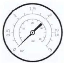
Fig. 3
6. STARTING UP
- Remove the lid of the filter trying not to damage the joints or the surrounding area around the lid.
- Check that all the filter components are in good condition and ensure that the laterals or the nozzles on the plate are secure, as they may have come loose or been damaged in transit.
- Fill the filter approximately half full of water.
- Introduce the sand, ensuring you first pour in a support layer, enough to cover the groove of the laterals or nozzle plate, covering them by approx. 10cm. This should be done very carefully so as not to damage any internal components. Whilst filling the filter with sand ensure that you distribute the sand evenly over the whole surface area.
- Introduce the desired sand size, up to the maximum filtration height limit, which should leave a distance between the sand level and the diffusses of around 25% the filter bed height.
- Carefully clean the filter neck, the seal and the lid before proceeding with the assembly. It is also advised to grease the screws before putting in the nuts.
- Close the filter placing the seal in its correct position.
- Once the filter is full and properly Closed, it is necessary to backwash the filter. To do this, follow the instructions in the section labelled 'backwash'.
7. WORKING CYCLES
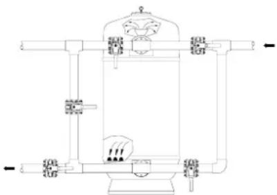
7.1 FILTRATION (Fig 4)
With the pump stopped set the valves to the position labelled filtration.
During the filter's normal operation, it is recommended to periodically check the pressure gauge and carry out a backwash when the difference in pressure is equal to or more than 0.8kg/cm^2 .
As the filter gets dirty during its use, the entrance experiences an increase in pressure at the same time as the exit shows a fall in working pressure.
natural_image
Pure technical line drawing of a mechanical device without any text, numbers, or symbolsFig. 4
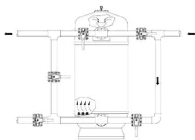
7.2 BACKWASH (Fig 5)
The bed of sand inside the filter forms thousands of channels through which the water flows and logically they collect impurities and solid deposits that the water brings with it to the filter. In time these deposits block the channels and it is periodically necessary to clean the filter to leave it in optimum working condition and drain the dirt that had collected.
It is recommended to backwash with water for 7 minutes at a speed of 40-50 m^3/h/m^2 .
It is advised to place a sight glass in the drainage pipework so that during the backwash you can see the dirt leaving the filter and in this way determine the duration of the backwash needed.
To carry out a backwash cycle, ALWAYS WITH THE PUMP SWITCHED OFF, set the valves to the backwash position indicated on the template.
natural_image
Pure technical line drawing of a mechanical device without any text, numbers, or symbolsFig. 5
ENGLISH
7.2.1 BACKWASH WITH AIR AND WATER (ONLY FOR FILTERS WITH NOZZLE PLATES OR DOUBLE LATERALS)
Air is used to dislodge and agitate the sand bed. This makes the backwash process more efficient in less time and saves a substantial amount of water.
This process is carried out in three phases:
- Inject air at a speed of approx. 60 m/h
- Inject water at a speed of approx. 50 m/h
- Inject water and air at a speed of no more than approx. 50 m/h
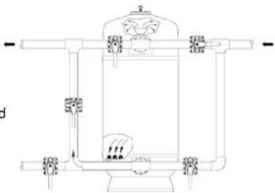
7.3 RINSING (Fig 6)
This operation is recommended straight after the backwash, in order to expel any remaining deposits that had penetrated the collectors during the backwash cycle.
This operation should last approx. 3 minutes and prevents cloudy water returning to the pool.
To carry out this operation set the valves to the rinse position (ALWAYS WITH THE PUMP SWITCHED OFF) and immediately afterwards reset the valves to the filter setting.
The rinse position can only be applied if the battery has 5 valves.
natural_image
Technical line drawing of a mechanical device with no visible text or symbolsFig. 6
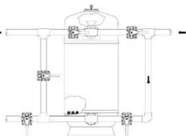
7.4 DRAIN (Fig 7)
When it is necessary to empty the pool and in the case of not having the drainage connected directly to the mains sewer system, you can empty it using the filter pump by positioning the valves to the 'drain' section on the template.
To do this and before commencing, the skimmer, overflow channel and pool cleaner valves must be Closed.
natural_image
Technical line drawing of a mechanical device with pipes and components (no text or symbols)Fig. 7
7.5 CLOSED
As the name indicates all the battery valves are Closed.
This operation is used when cleaning or maintenance work is carried out on the filter or pre-filter, etc.
8. VALVE BATTERIES. VALVE POSITION IN EACH OPERATION.
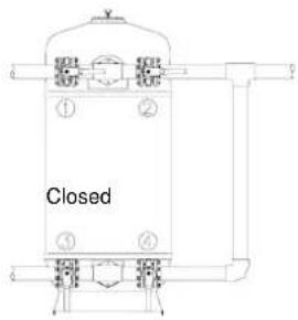
8.1 BATTERIES WITH 4 VALVES
Template of operations for batteries with 4 valves:
| POSITION 1 2 3 4 | |||
| Filtration Closed Opened Opened Closed | |||
| BACKWASH Opened Closed Closed Opened | |||
| DRAIN Opened Opened Closed Closed | |||
| CLOSED Closed | Closed | Closed |
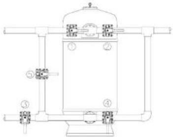
8.2 BATTERIES WITH 5 VALVES
Template of operations for batteries with 5 valves:
| POSITION 1 | 2 3 4 5 | ||||
| FILTRATION | Closed Opened | Opened Closed | Closed | ||
| BACKWASH | Opened Closed | Closed Opened | Closed | ||
| RISING | Closed Opened | Closed Closed Opened | |||
| DRAIN | Opened Opened | Closed Closed Closed | |||
| CLOSED | Closed Closed | Closed Closed Closed |
natural_image
Technical line drawing of a vertical pressure vessel with internal components and piping (no text or labels)Note: To carry out any operation indicated on the template, the pump must be OFF.
8.3 SELECTOR VALVE
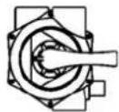
Each operating procedure depends on the position of the multiport valve handle, as it is indicated.
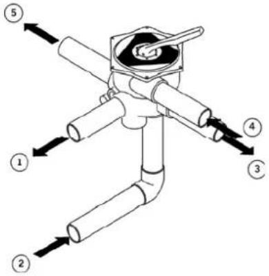
- Water inlet to filter
- Water outlet from filter
- Return to pool – with no circulation through the filter
- From pump
- To drain
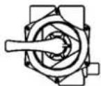
FILTRATION
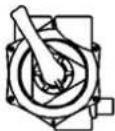
DRAIN
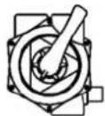
CLOSED
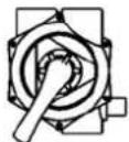
RINSING
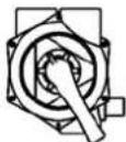
RECIRCULATION
BACKWASH
Warning: The handle position of the selector valve should not be changed with the water pump functioning.
9. DRAINING THE SAND FROM THE FILTER
When you need to drain the sand, due to an accident or because you want to change the sand due to wear and tear, follow the following steps:
- Drain the water from the filter
- Drain the sand from the filter
- To fill the filter with sand again, follow the instructions for 'Starting Up'
Use the time the filter is empty to check all the internal components, most importantly the laterals or nozzles and replace any that are damaged.
10. OTHER RECOMMENDATIONS
The interior assembly, the number of laterals and diffusers, varies depending on the size and type of filter. The diffusers function is to distribute the water in the most even way possible over the filtration bed. The laterals function is to collect the water once filtrated and channel it to the exit of the filter.
Each filter is equipped with a manual air drain valve in the upper part of the filter. Likewise, all filters have a manual water drain valve in the lower part of the filter.
Once the swimming pool installation is complete, it is recommended to give the filter a good clean with pressurised water in order to remove all dust and dirt accumulated during construction or installation.
If the installation is likely to be left for a long period of time without being used, it is advisable to drain the filter of water.
The filters located outdoors could loose colour intensity or external brightness, this is caused by the sun radiation and for this reason it is recommended to place them out of the direct reach of the sun.
11. MAINTENANCE
A regular and thorough clean is necessary for the maintenance of your pool, in the long term this will save time, the equipment will last longer and the water will be of a better quality.
For the correct maintenance of the filtration equipment (pump, valves, etc.) follow the manufacturers instructions.
Periodically inspect the filter media and all the filter components (diffusers, laterals, air and water drain valves, pipes, seals etc.) including the polyester tank, replacing or repairing any damaged parts
Periodically clean the filter with pressurised water to remove dust accumulated over time. Do not use solvents that could damage the plastic parts or the sight glass.
If you close the pool in winter adequately drain the equipment to prevent any damage from ice.
- TABLE HEAD LOSS FROM SAND FILTERS WITH VALVE BATTERIES

line
| Filtration speed m³/h/m² | Load loss m | | ------------------------ | ----------- | | 0 | 1 | | 20 | 1 | | 30 | 2 | | 40 | 3 | | 50 | 5 | | 60 | 6 |13. SAFETY WARNINGS
Switch off the pump before operating any valve.
Do not connect the filter directly to the drinking water mains as the pressure can rise and exceed the maximum authorised working pressure of the filter.
Remember that it is very important to install the supports of the valves to prevent any filter connection from breaking.
The filters are designed to be highly resistant to internal pressure, but at the same time they are very susceptible to exterior knocks.
If the facility has more than one filter installed on the same battery there should be a valve on each of the connections to allow the filter to be completely isolated.
Under no circumstances should you exceed the maximum working pressure, indicated on the filter characteristics plate.
The filters are not designed to support internal vacuum pressure; therefore this situation should be avoided.
- POSSIBLE FAULTS
| PROBLEM | CAUSE | SOLUTION |
| No filtered water flowing | The filter is dirty.The collecting basket is covered. | Start backwash.Clean the collecting basket. |
| You observe characters in the sand bed | Formation of preferential channels, lack or backwash or broken collector | Start a backwash.Drain the sand and check if the collector is defective.Replace the collector is defective.Replace the sand. |
| Pressure gauge oscillates violently | The pump is impelling airSuction half Closed | Check the whole installation and eliminate possible leaksCheck the suction valves are completely open |
| Sand is entering the pool from the filter | There is something broken in the collector system | Repair the collector system |
| Sand is escaping to the drain during backwash | Excessive water flow during backwash or excessive sand level | Reduce the flow rate during backwash or reduce the sand level |
natural_image
Technical line drawing of a cylindrical industrial vessel with internal components and flow arrows (no text or symbols)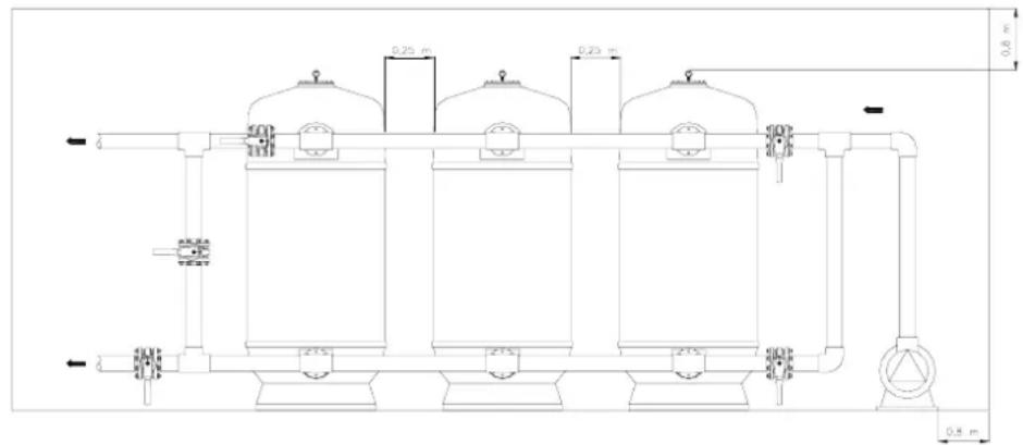
Fig. 1
natural_image
Two technical diagrams showing a cylindrical tank with internal components and a cross symbol (no text or labels)Fig. 2
5.1 INSTALLATION DES MANOMETRES (Fig. 3)
Fig. 4
7.2 LAVAGE (Fig. 5)
natural_image
Technical line drawing of a mechanical device with no visible text or symbolsFig. 5
FRANÇAIS
7.2.1 LAVAGE PAR AIR ET EAU (SEULEMENT POUR FILTRES A CREPINES OU DOUBLE COLLECTEUR)
8.2 BATTERIE DE 5 VANNES
natural_image
Technical line drawing of a vertical pressure vessel with numbered components (no text or symbols)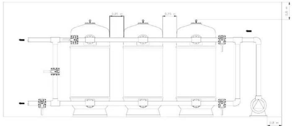
Fig. 1
natural_image
Two technical diagrams showing a cylindrical tank with internal components and a cross symbol (no text or labels)Fig. 2
5.1 MANÓMETRO (Fig. 3)
natural_image
Pure technical line drawing of a mechanical or electrical component without any text, numbers, or symbolsFig. 4
7.2 LAVADO (Fig. 5)
natural_image
Technical line drawing of a mechanical device with no visible text or symbolsFig. 7
7.5 CERRADO
8.2 BATERÍAS DE 5 VÁLVULAS
natural_image
Technical line drawing of a vertical pressure vessel with numbered components (no text or symbols)Fig. 1
natural_image
Two technical line drawings of industrial tanks with circular components and a crossed-out black X symbol (no text or labels)Fig. 2
natural_image
Pure technical line drawing of a mechanical or electrical component without any text, numbers, or symbolsFig. 4
7.2 LAVAGGIO (Fig. 5)
8.2 BATTERIE A 5 VALVOLE
natural_image
Technical line drawing of a vertical pressure vessel with numbered components (no text or symbols)According to the model, the components might change in size or position or could not be present.
natural_image
Two technical illustrations of industrial tanks with circular components, one crossed out by a black X (no text or symbols)Fig. 2
5.1 INSTALLATION DER MANOMETER (Fig. 3)
natural_image
Pure technical line drawing of a mechanical device without any text, numbers, or symbolsFig. 4
7.2 WASCHVORGANG (Fig. 5)
natural_image
Pure technical line drawing of a mechanical or industrial device with no text, numbers, or symbolsFig. 5
8.2 BATTERIEN MIT 5 VENTILEN
natural_image
Technical line drawing of a vertical pressure vessel with numbered components (no text or symbols)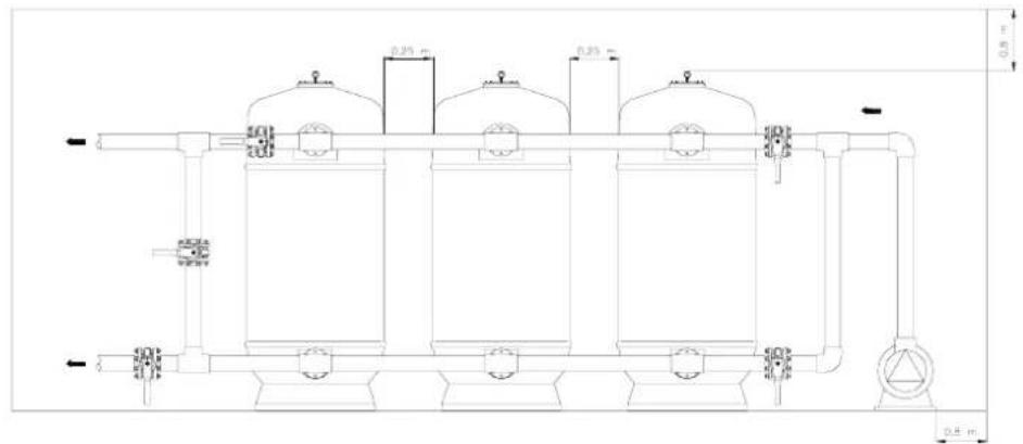
Fig. 1
natural_image
Two technical line drawings of industrial tanks with circular components, one marked with a cross symbol (no text or labels present)natural_image
Pure technical line drawing of a mechanical device without any text, numbers, or symbolsFig. 4
7.2 LAVAGEM (Fig. 5)
8.2 BATERIAS DE 5 VÁLVULAS
natural_image
Technical line drawing of a cylindrical industrial vessel with internal components and directional arrows (no text or symbols)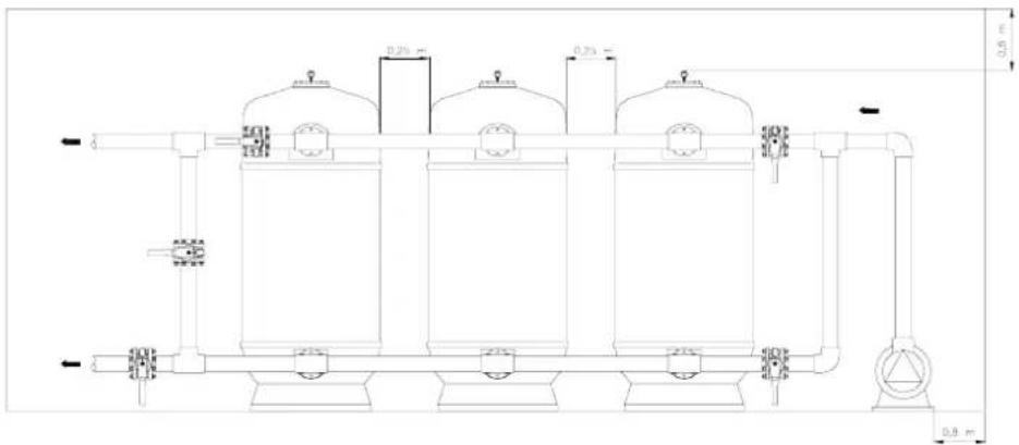
Rys. 1
natural_image
Two technical line drawings: a cylindrical tank with internal components and a cross-shaped device (no text or symbols)R
Rys. 2
5.1 MANOMETREM (Rys. 3)
7. NORMALNY CYKL PRACY
7.1 FILTROWANIE (Rys. 4)
Rys. 4
7.2 CZYSZCZENIE (Rys. 5)
natural_image
Technical line drawing of a mechanical device with no visible text or symbolsRys. 5
POLSKI
7.2.1 CZYSZCZENIE POWIETRZEM I WODĄ (TYLKO DLA FILTRÓW Z KOSZAMI SSAWNYMI LUB PODWÓJNYM KOLEKTOREM)
8.2 ZESPOŁY 5-ZAWOROWE
natural_image
Technical line drawing of a vertical pressure vessel with numbered components (no text or symbols)
- CHECK THE PACKAGING
- GENERAL SPECIFICATIONS
- IDENTIFICATION OF COMPONENTS
- ENGLISH
- IDENTIFICATION OF COMPONENTS
- INSTALLATION
- Correct installation of the filters:
- INSTALLATION OF THE PRESSURE GAUGES (Fig 3)
- STARTING UP
- WORKING CYCLES
- FILTRATION (Fig 4)
- BACKWASH (Fig 5)
- BACKWASH WITH AIR AND WATER (ONLY FOR FILTERS WITH NOZZLE PLATES OR DOUBLE LATERALS)
- RINSING (Fig 6)
- DRAIN (Fig 7)
- CLOSED
- VALVE BATTERIES. VALVE POSITION IN EACH OPERATION.
- BATTERIES WITH 4 VALVES
- BATTERIES WITH 5 VALVES
- SELECTOR VALVE
- DRAINING THE SAND FROM THE FILTER
- OTHER RECOMMENDATIONS
- MAINTENANCE
- SAFETY WARNINGS
- INSTALLATION DES MANOMETRES (Fig. 3)
- LAVAGE (Fig. 5)
- FRANÇAIS
- LAVAGE PAR AIR ET EAU (SEULEMENT POUR FILTRES A CREPINES OU DOUBLE COLLECTEUR)
- BATTERIE DE 5 VANNES
- MANÓMETRO (Fig. 3)
- LAVADO (Fig. 5)
- CERRADO
- BATERÍAS DE 5 VÁLVULAS
- LAVAGGIO (Fig. 5)
- BATTERIE A 5 VALVOLE
- INSTALLATION DER MANOMETER (Fig. 3)
- WASCHVORGANG (Fig. 5)
- BATTERIEN MIT 5 VENTILEN
- LAVAGEM (Fig. 5)
- BATERIAS DE 5 VÁLVULAS
- MANOMETREM (Rys. 3)
- NORMALNY CYKL PRACY
- FILTROWANIE (Rys. 4)
- CZYSZCZENIE (Rys. 5)
- POLSKI
- CZYSZCZENIE POWIETRZEM I WODĄ (TYLKO DLA FILTRÓW Z KOSZAMI SSAWNYMI LUB PODWÓJNYM KOLEKTOREM)
- ZESPOŁY 5-ZAWOROWE
Brand : ASTRALPOOL
Model : Delta
Category : Water filter