Boise - Pump ASTRALPOOL - Free user manual and instructions
Find the device manual for free Boise ASTRALPOOL in PDF.
User questions about Boise ASTRALPOOL
0 question about this device. Answer the ones you know or ask your own.
Ask a new question about this device
Download the instructions for your Pump in PDF format for free! Find your manual Boise - ASTRALPOOL and take your electronic device back in hand. On this page are published all the documents necessary for the use of your device. Boise by ASTRALPOOL.
USER MANUAL Boise ASTRALPOOL
This manual contains basic information on the safety measures to be adopted during installation and start-up. The fitter and the user must therefore read the instructions before installation and start-up.
1.GENERAL SAFETY INSTRUCTIONS
These symbols indicate the possibility of danger where the corresponding instructions are not followed.

DANGER. Risk of electrocution.
Failure to abide by these instructions may lead to the risk of electrocution.

DANGER.
Failure to abide by these instructions may lead to the risk of injury or damage.

WARNING.
Failure to abide by these instructions may lead to the risk of damage to the pump or the installation.
2.GENERAL SAFETY REGULATIONS
GENERAL

-
The machines indicated in this Manual are especially designed for the pre-filtering and recirculation of water in swimming pools.
-
They are designed to work with clean water at temperatures not exceeding 35^ C .
-
They must be installed in line with the specific instructions for each installation.
-
Current regulations regarding accident prevention must be respected.
-
Any modification to be made to the pump requires the prior authorisation of the manufacturer. Original spare parts and accessories authorised by the manufacturer ensure greater safety. The pump manufacturer is exempt from all liability regarding any damage caused by unauthorised spare parts or accessories.

-
While operating, the electrical parts of the pump are live. Work on each machine or on the equipment connected to it may only be carried out after having disconnected it from the electricity mains supply and after having disconnected the start-up devices.
-
Users must ensure that all assembly and maintenance work is carried out by qualified and authorised personnel who have carefully read the installation and service instructions.

-
Machine operating safety is only guaranteed under compliance with and respecting that indicated in the installation and service instructions.
-
The limit values indicated in the technical specifications must under no circumstances be exceeded.
-
In the event of defective operation or faults, contact your supplier or nearest representative.
WARNING DURING INSTALLATION AND ASSEMBLY WORK

- When connecting the electrical wiring to the machine motor, check the layout inside the connection box and make sure there are no pieces of wiring inside after it has been closed and that the earthing conductor is correctly connected. Connect the motor in line with the wiring diagram attached to the machine.
- Make sure that the electrical wiring connections to the machine terminal box are well mounted and screwed tight to the connection terminals.
-
The electrical installation of the pump must include differential protection of a value no greater than 30mA .
-
Check that the terminal box seal is being used correctly to prevent water from entering the electric motor terminal box. Also check that the gland inside the terminal box cable duct has been fitted and tightened.
- Make sure that water is unable to enter the motor or the live electrical parts.
- Where the intended use is not as indicated, additional technical adaptations and regulations may be required.
WARNING DURING START-UP

Before starting the machine, check the calibration of the electric protection devices on the motor and that the protection against electrical and mechanical contacts are correctly positioned and secure.
NOTE
The pool should not be used while the pumping equipment is running.
The pump must not be used when people in contact with the water.
WARNING DURING ASSEMBLY AND MAINTENANCE WORK
- National installation regulations must be taken into account when assembling and installing the pumps.
- Make sure that water is unable to access the motor and the live electrical parts.
- Avoid contact at all times - even accidentally - with moving machine parts while the machine is running and/or before it comes to a complete standstill.
- Wait for the machine to come to a halt before handling it.
- Prior to any electrical or mechanical maintenance work, make sure that the machine has been disconnected from the mains and that the start-up devices are blocked.
-
Follow the steps below before handling the machine:
-
Disconnect the machine from the mains.
- Block all start-up devices.
- Check that there is no voltage in the circuits, even in the auxiliary circuits and additional services.
- Wait for the impeller to come to a complete standstill.
The list indicated must be used as a guideline and is not binding for safety purposes. There may be particular safety regulations in specific standards.
-
For regular control:
-
Check that the mechanical parts are tightly secured and check the condition of the screws supporting the machine.
- Check that the power conductors and isolating parts are in their correct position, are secure and in a good state of repair.
- Check the temperature of the machine and the electric motor. In the event of an anomaly, stop the machine immediately and repair.
- Check for machine vibrations. In the event of an anomaly, stop the machine immediately and repair.
Due to the complex nature of the cases treated, the installation, user and maintenance instructions contained in this manual do not seek to examine all possible and imaginable cases of service and maintenance. Should you require additional instruction or have specific problems, please do not hesitate to contact the distributor or the machine manufacturer directly.
The electrical installation should be done by someone qualified in working with electrical equipment. This equipment is not designed for those with physical, sensory or mental handicap or people lacking in experience, unless done under supervision or with instructions of use from a person in charge of safety.
Do not permit children nor adults to sit or lean on the equipment. Children should be supervised to ensure that they do not play with the equipment.
3. INSTALLATION AND ASSEMBLY
GENERAL

- Our pumps may only be assembled and installed in pools or ponds that are compliant with HD 384.7.702. Should you have any doubts, please consult your specialist.
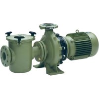
- The pumps are fitted with a pre-filter with a basket inside to collect any large particles, as they may damage the hydraulic part inside the pump. This pre-filter means that the pump must be assembled horizontally.
- All pumps are fitted with a foot with two holes in it to anchor it to the ground (Fig. 1).
PIPING

- The piping must be connected by gluing it to the fittings supplied with the pump; the fitting connections to the suction and return ports on the pump are threaded and include seals to prevent water loss (Fig. 2).
- The return pipes must be fitted completely perpendicular and centred in relation to the port to be connected to prevent the pump and the pipe from being subjected to external stress that, apart from making fitting difficult, could break them (Fig. 2).
- The suction piping will be installed on a slight 2% slope towards the pump to avoid the formation of air pockets (Fig. 2).
- To ensure the pump works correctly, prime the pump pre-filter until water rises up through the suction pipe (Fig.3).
LOCATION

- To improve pump performance, it should be fitted underneath the water level in the pool.
- Where a self-priming pump is to be fitted above the water level, the difference in height must be no more than 2 metres (Fig. 4), ensuring that the suction pipe is as short as possible as a long pipe would increase drainage times and load losses in the installation.
- Make sure that the pump is safe from possible flooding and receives dry ventilation.

ELECTRICAL INSTALLATION

- The electrical installation must include a multiple separation system with contact openings of at least 3mm .
- Only stiff wiring can be used for mains connections. Where flexible wiring is used for mains connections it must include terminals for connection to the pump motor terminals.
- With any type of pump, 0.03 A differential protection must be fitted for electricity leakage protection (indicated on the diagrams).
- Adjust the value of the thermal relay appropriately depending on the pump current.
For pumps with a single-phase motor:
- Thermal protection must be fitted. Installation with a switch is sufficient, in line with the "Mains connections" diagram.
- A motor guard with magneto-thermal protection must be used.
- The adjustment data for the thermal relay is to be used as a guideline, as the motor is already fitted with protection.
- For 230V , use a H07 RN-F3 type connection sleeve with a cable section that adapts to the power of the motor and to the length of the cable.
For pumps with a three-phase motor:
- A motor guard with magneto-thermal protection must be used.
- The pump must be protected against overloads with a cut-off switch for the motor.
For voltage ranges other than 230/400V, 400/690V, connect the lowest voltage at and the highest at Y.
- For AC, use a H07 RN-F3 type connection sleeve with a cable section that adapts to the power of the motor and the length of the cable.
-
The mains cable may only be connected by skilled, authorised personnel (connection type Y).
-
Before connecting the motor, check the type of fuse required.
- Check the correct layout and connection of the earthing cable in the equipment.
- It is essential that the electrical installation and connection conditions are respected. Failure to do so may lead to the pump manufacturer declining all responsibility and rendering the guarantee null and void.
- The motors are subject to EEC standards with IP-55 (plastic pumps) and IP-54 (cast iron pumps) protection.
- Special regulations may exist for the installation.
- Unsuitable mains connections involve the risk of death.
4. START-UP INSTRUCTIONS
PRIOR TO START-UP

-
Carry out the following operations before starting the pump:
-
Fill the pump with water through the pre-filter until it rises up through the suction pipe.
- Should the basket be removed during these operations, do not forget to replace it to prevent large particles from entering the pump that could block it.
-
Check that the mains voltage and power correspond with those indicated on the pump characteristics plate.
-
The pumps must not be run without the pre-filter having first been filled with water. Where this is not the case, the mechanical gasket may be damaged, leading to a loss of water.

- Check that the motor rotates in the correct direction by means of the fan located at the back of the motor that can be seen through the view hole on the fan cover (Fig. 5).
- Check that the pump shaft turns freely.
START-UP

- Open all the valves and connect the motor.
- Wait for a reasonable time for the piping to self-prime.
5.MAINTENANCE

- Clean the pre-filter basket regularly to avoid drops in pressure. To prevent the basket from breaking, do not hit it during the cleaning process
- Should the pump stop, check that consumption of the running motor in amperes is equal to or below that indicated on the manufacturer's characteristics plate. If this information is available, contact the nearest Technical Assistance Service.

- Where the amperage is higher, consult the manufacturer.
- Empty the pump if it is to remain at a standstill for a certain length of time, especially in cold countries where there is a risk of freezing.
-
Remove the purge cap to empty the pump.
-
Pump components that, due to their normal use, suffer wear and/or tear must be regularly replaced to ensure good pump performance. The following table shows the perishables and/or consumables used in the pump and their estimated working life.
| COMPONENT DESCRIPTION ESTIMATED WORKING LIFE | |
| 0 rings and general seals 1 year | |
| Mechanical lock 1 year | |
| Bearings 1 year | |
The estimated working life for the above parts has been established in line with normal product working and installation conditions. Follow the instructions in the installation manual to ensure the working life of the pump.
6.REMOVAL

- The motor unit can be removed from the pump body without having to disconnect the pump's suction and return pipes.
- To remove the Motor unit from the pump body, remove the screws joining them together.
7.TROUBLESHOOTING
- The pump is not primed
- The pump releases only a small flow of water
-
The pump makes a noise
-
The pump will not start
- The motor is making a noise but will not start
- The motor stops
| 1 | 2 | 3 | 4 | 5 | 6 | CAUSES | SOLUTIONS | |
| · | · | Air entering the suction pipe | ||||||
| · | Filter cap badly sealed Clean the filter cap and check the condition of the rubber seal | |||||||
| · | · | Inverted motor turning Invert 2 power phases | ||||||
| ··· | Wrong voltage | |||||||
| · | Pre-filter blocked Clean filter | |||||||
| · | Load loss in drainage | |||||||
| · | Pump incorrectly secured | |||||||
| · | Motor blocked | |||||||
| · | Increased temperature in the terminal box due to electric arc | Check the terminal box connections | ||||||
| · | The thermal protection trips | |||||||
| · | Incorrect terminal box connections |