USER MANUAL L4PL GRE
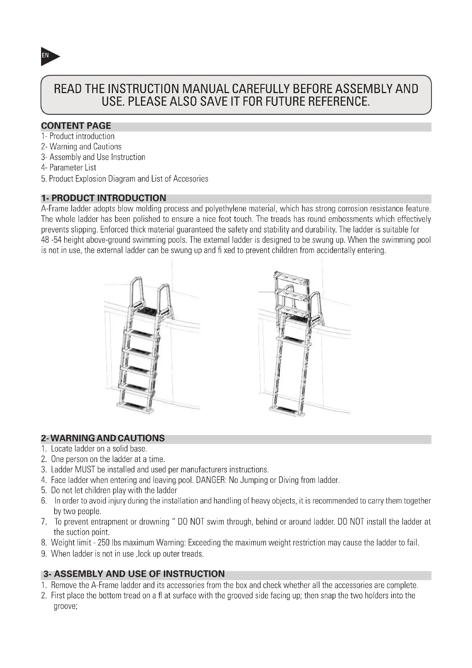
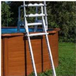
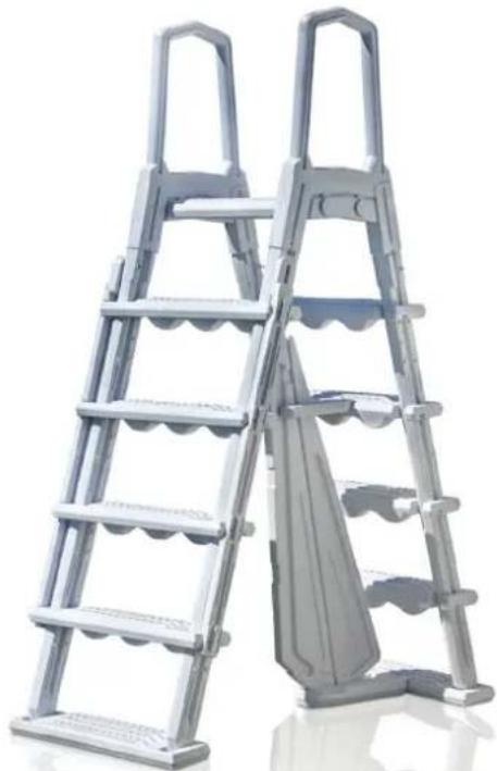
Plastic material. Platform included.
natural_image
White metal ladder leaning against a blue pool structure on a wooden bench, surrounded by grass and trees (no text or symbols visible)
natural_image
Exterior view of a wooden fence structure with a metal ladder leaning against a green lawn and a pool in the background (no signage or text visible)
natural_image
Metal double-lane ladder with a side panel, shown against a plain white background (no text or symbols visible)
Owner's Manual - Manual de Instrucciones Manuel d'instructions - Bedienungsanleitung Manuale delle instruzioni - Handleiding met instructies Manual de instruções - Instrukcja obsługi
DISTRIBUTED BY / DISTRIBUIDO POR / DISTRIBUÉ PAR / VERTRIEB DURCH / DISTRIBUITO DA / GEDISTRIBUEERD DOOR / DISTRIBUÍDO POR / WYPRODUKOWANY PRZEZ:
MANUFACTURAS GRE, S.A. ARITZ BIDEA N° 57 BELAKO INDUSTRIALDEA, APARTADO 69 - 48100 MUNGUIA (VIZCAYA) ESPAÑA N° Reg. Ind. 48-06762
MADE IN CHINA / FABRICADO EN CHINA / FABRIQUÉ AU CHINE / HERGESTELLT IN CHINA / PRODOTTO IN CHINA / GEPRODUCEERD IN CHINA / FABRICADO NA RPC /
WYPRODUKOWANO W CHINACH
READ THE INSTRUCTION MANUAL CAREFULLY BEFORE ASSEMBLY AND USE. PLEASE ALSO SAVE IT FOR FUTURE REFERENCE.
CONTENT PAGE
1- Product introduction
2- Warning and Cautions
3- Assembly and Use Instruction
4- Parameter List
5. Product Explosion Diagram and List of Accessories
1- PRODUCT INTRODUCTION
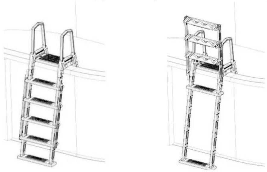
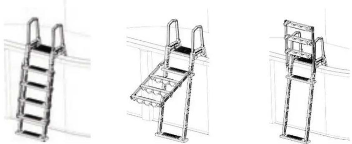
A-Frame ladder adopts blow molding process and polyethylene material, which has strong corrosion resistance feature. The whole ladder has been polished to ensure a nice foot touch. The treads has round embossments which effectively prevents slipping. Enforced thick material guaranteed the safety and stability and durability. The ladder is suitable for 48 -54 height above-ground swimming pools. The external ladder is designed to be swung up. When the swimming pool is not in use, the external ladder can be swung up and fixed to prevent children from accidentally entering.
natural_image
Technical line drawings of two different metal ladder structures (no text or symbols)
2- WARNING AND CAUTIONS
- Locate ladder on a solid base.
- One person on the ladder at a time.
- Ladder MUST be installed and used per manufacturers instructions.
- Face ladder when entering and leaving pool. DANGER: No Jumping or Diving from ladder.
- Do not let children play with the ladder
- In order to avoid injury during the installation and handling of heavy objects, it is recommended to carry them together by two people.
- To prevent entrapment or drowning "DO NOT swim through, behind or around ladder. DO NOT install the ladder at the suction point.
- Weight limit - 250 lbs maximum Warning: Exceeding the maximum weight restriction may cause the ladder to fail.
- When ladder is not in use, lock up outer treads.
3- ASSEMBLY AND USE OF INSTRUCTION
- Remove the A-Frame ladder and its accessories from the box and check whether all the accessories are complete.
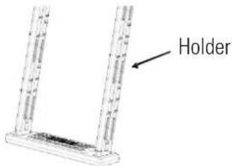
- First place the bottom tread on a fl at surface with the grooved side facing up; then snap the two holders into the groove;
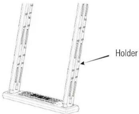
Note: The two holders need to be snapped into the groove in the same direction.
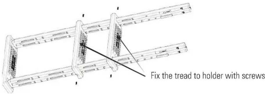
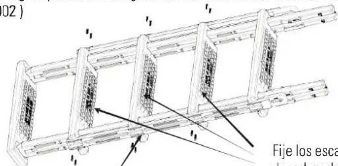
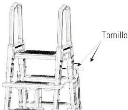
- Install four treads to the holder, see the picture as below. Fix the top tread to the holder by #10x1-1/4 screws.
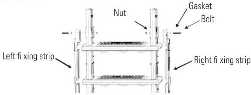
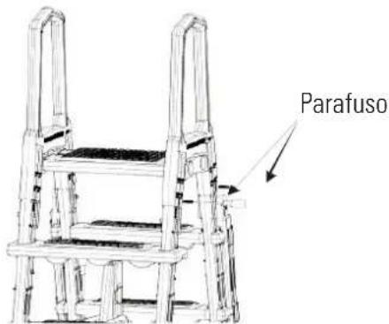
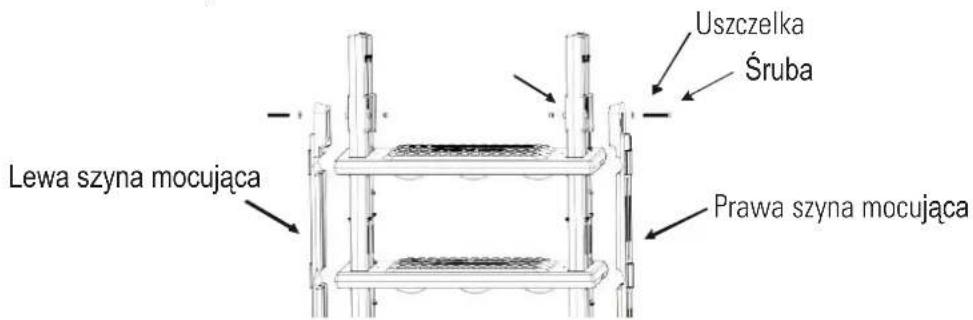
- Fix the left and right fixing strips with bolt & gasket(M6), and nut M6*85!, do not over tighten (the accessories are in screw kit 5862050002)
- Use # 10x1-1 / 4 screws to fix other three treads. Then put aside for further processes.
- Put another bottom tread on a flat surface with the grooved side facing up; then snap the two holders into the groove. Note: The two holders need to be snapped into the groove in the same direction.
- Fix the treads to the holders with screws with #10x1-1 / 4 .
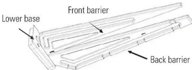
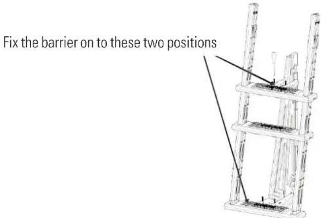
- Place the Lower Base on a level surface. Snap front barrier into the groove on the lower base facing round edge. Snap back barrier into the groove on the lower base facing the straight side.
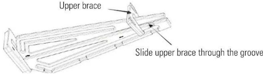
- Slide upper brace over front barrier as shown. Slide upper brace through the groove in the Back Barrier and push down lightly to secure.
- Fix lower base of entrapment barrier into bottom step of the Inside portion of the Ladder with 2 pieces 10 × 1 - 1 / 4 screws.
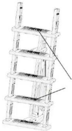
- Fix the remaining two treads with 10x1-1/4 screws to the holder in the groove positions
natural_image
Technical line drawing of a multi-tiered ladder structure with no visible text or symbols
Install the treads with screws
- This ladder is designed to fit multiple pool heights.
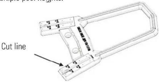
If you pool height is 52 .Locate the first line on the handrail of the ladder. Using a hacksaw cut the handrail evenly through both sides.
If the pool height is 48 " locate the second line on the handrail, and using a hacksaw cut the handrail evenly through both sides# Locate the line on the holder and cut the redundancies evenly through both sides.
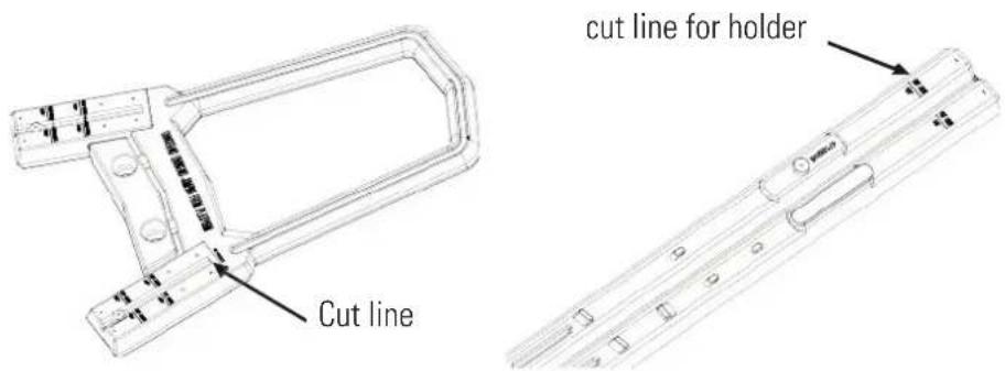
No cut needed, if your pool height is 54
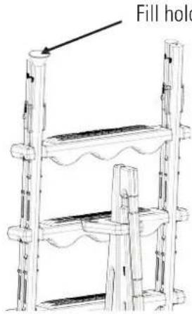
- Using a funnel fill both holders with sand. Use approximately 20 Lbs. of sand in each holder. The barrier in step 11 have the front and back barrier!
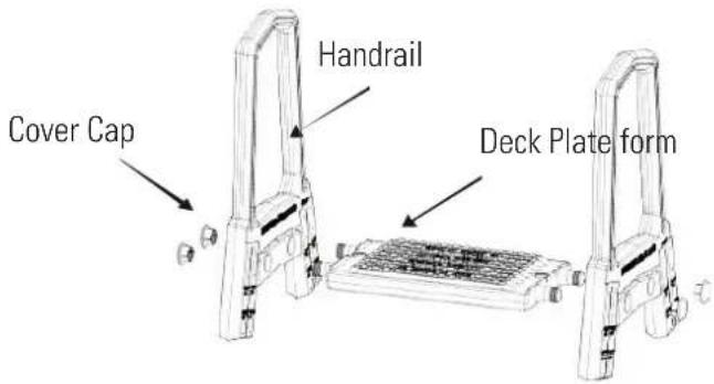
- Assemble handrails to the platform, center cover cap opening on side of handrail where platform was just attached. Using a rubber mallet/hammer, tap on cap until the cap is flush with handrail.
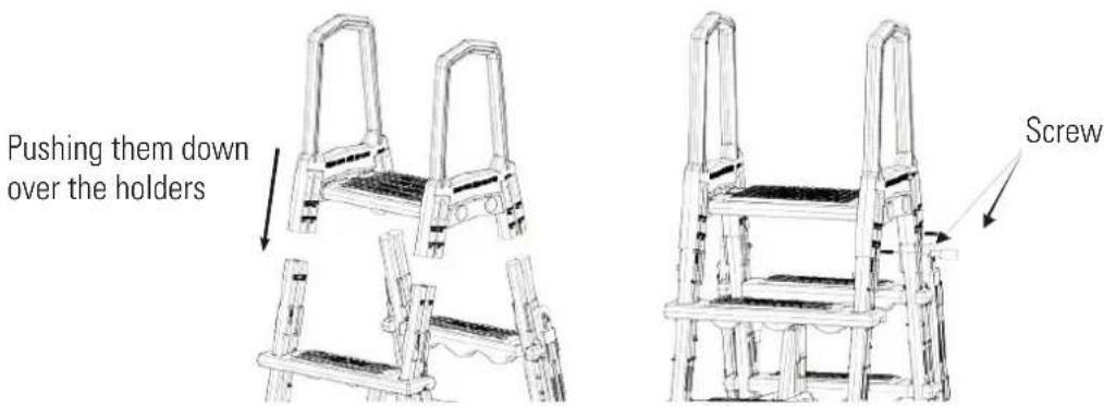
- Attach handrails by pushing them down over the holders.
- Secure all handrails to the legs with #10 1-1/4# screws\$
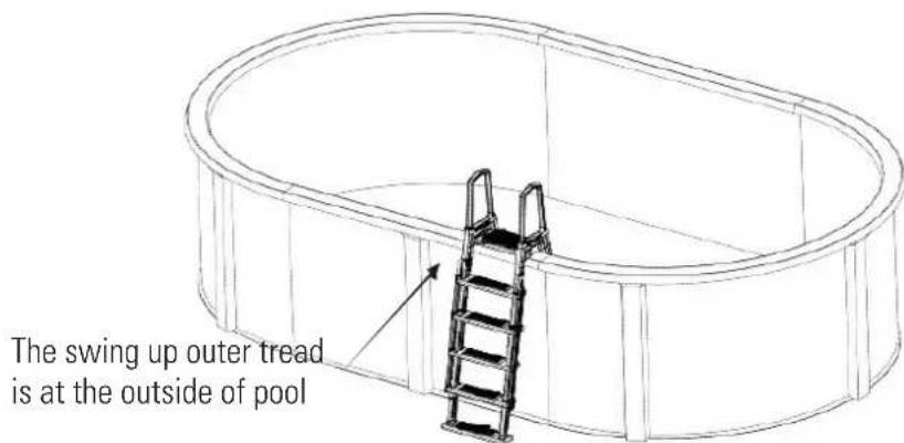
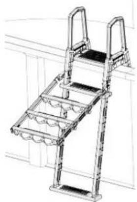
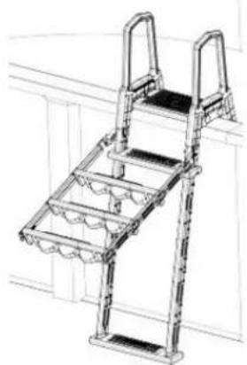
- Place assembled ladder inside the pool where you would like to enter and exit. The entrapment barrier should be inside of the pool. Once the ladder is placed in the pool, tip the ladder forwards and backwards and side to side to release any air that may be trapped inside.
When a Ladder is installed it is recommended that a Step Mat should be installed underneath. THIS ITEM IS SOLD SEPARATELY
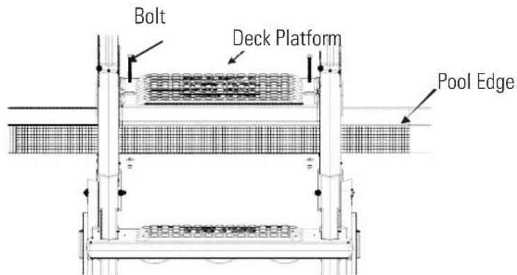
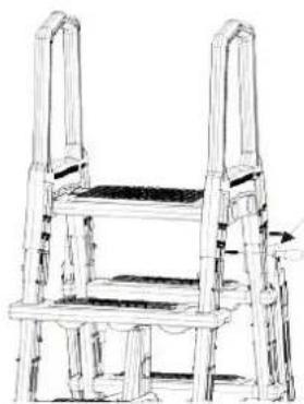
- A-Frame ladder must be fixed on the edge of the pool. First, align the two holes on the surface of the deck platform with the edge of the pool, mark the hole positions at the edge of the pool with a fine marker pen, then drill through the edge of the swimming pool with a 5/16 "drill bit, and finally use bolts, nuts and washers to fix the ladder on the edge of the swimming pool.
| Use 5862050000 screw kit 2.5 bolt if your pool height is 48 |
| Use 5862050001 screw kit 5 bolt if your pool height is 52 |
| Use 5862050001 screw kit 5 bolt if your pool height is 54 |
Routine Maintenance
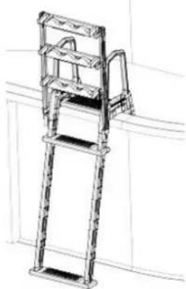
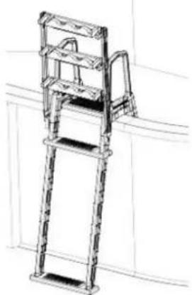
When the swimming pool is not in use, it is recommended to flip the outer ladder upwards, then push it down and fix it.
natural_image
Three technical line drawings of metal ladder structures, shown from different angles (no text or symbols present)
- In winter, the ladder must be removed.
- When removing the ladder, it is recommended to wash the ladder with fresh water to remove the chemicals on the surface.
- Store the ladder in a warm and dry place for reuse in the next year.
4- PARAMETER LIST
| No. Description Specification | |
| 1 Application 48 -54 | height above ground pool | |
| 2 Weight limit 250 lbs | | |
| 3 Material Polythene | | |
| 4 Products Size | 1070*646*1966 MM | |
| 5 | Gross Weight | |
| 6 | Package Size 600*200*1510MM | |
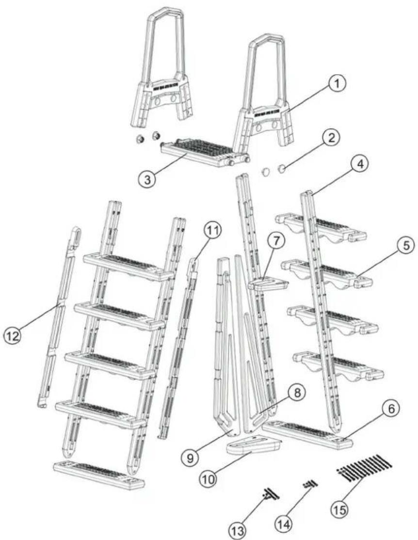
5- PRODUCT EXPLOSION DIAGRAM AND LIST OF ACCESORIES
| No. | Part Number | Description | Qty |
| 1 47155001 | Handrail | 2 | |
| 2 48850112 | Cover Cap | 4 | |
| 3 47155011 | Deck Platform | 1 | |
| 4 47155005 | Holder | 4 | |
| 5 47155002 | Tread 8 | | |
| 6 47155008 | Bottom tread | 2 | |
| 7 47155003 Upper Brace 1 | | |
| 8 47155009 Front Barrier 1 | | |
| 9 47155010 Back Barrier 1 | | |
| 10 47155004 Lower Base 1 | | |
| 11 47155007 Left Fixing Strip 1 | | |
| 12 47155006 Right Fixing Strip 1 | | |
| 13 5862050001 Screw Kit (5′′ Bolt) | 1 | |
| 14 5862050000 Screw Kit (2.5′′ Bolt) | 1 | |
| 15 5862050002 Screw Kit (1-1 / 4′′ Bolt) | 1 | |
LEA DETENIDAMENTE EL MANUAL DE INSTRUCCIONES ANTES DEL MONTAJE Y EL USO.GUÁRDELO PARA CONSULTARLO MÁS ADELANTE.
ÍNDICE
natural_image
Technical line drawings of two different metal ladder structures (no text or symbols)
- Fix the left and right fixing strips with bolt & gasket(M6), and nut M6*85!, do not over tighten (the accessories are in screw kit 5862050002)
natural_image
Technical line drawing of a ladder structure with a tool, no text or symbols present
natural_image
Technical line drawing of a multi-tiered ladder structure with no visible text or symbols
natural_image
Technical line drawing of a two-hinged ladder device with a horizontal guide rail, showing structural components and movement direction (no text or symbols)
natural_image
Three technical line drawings of metal ladder structures, shown from different angles (no text or symbols present)
LISEZ ATTENTIVEMENT LA NOTICE AVANT LE MONTAGE ET L'UTILISATION. CONSERVEZ-LA POUR DE FUTURES CONSULTATIONS.
SOMMAIRE
1- INTRODUCTION DU PRODUIT
natural_image
Technical line drawings of two different metal ladder structures (no text or symbols)
2- AVERTISSEMENTS ET PRÉCAUTIONS
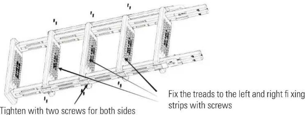
Tighten with two screws for both sides
Fix the treads to the left and right fixing strips with screws
natural_image
Technical line drawing of a ladder structure with a diagonal guide and a pointer (no text or symbols)
natural_image
Technical line drawing of a multi-tiered ladder structure with no visible text or symbols
natural_image
Illustration of a metal ladder with multiple steps, mounted on a wall (no text or symbols)

natural_image
Line drawing of a metal ladder structure with handle and frame (no text or symbols)
natural_image
Line drawing of a metal ladder structure with ladder and frame (no text or symbols)
natural_image
Line drawing of a multi-level metal ladder structure (no text or symbols)

natural_image
Line drawing of a multi-level metal ladder structure (no text or symbols)
natural_image
Technical line drawing of a ladder structure with a tool, no text or symbols present
natural_image
Line drawing of a multi-level ladder structure with no text or symbols
natural_image
Three technical line drawings of metal ladder structures, shown from different angles (no text or symbols present)
DI ISTRUZIONI PRIMA DELL'ASSEMBLAGGIO E DELL'UTILIZZO. CONSERVARLO PER RIFERIMENTI
CONTENUTO
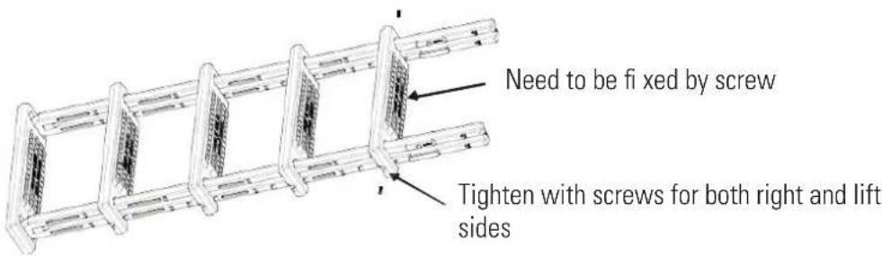
Need to be fixed by screw
Tighten with screws for both right and lift sides
natural_image
Line drawing of a multi-tiered ladder structure with no text or symbols
natural_image
Illustration of a metal ladder with six horizontal ladders, mounted on a wall (no text or symbols)
natural_image
Line drawing of a metal ladder structure with multiple stairs and a handle, mounted on a wall (no text or symbols)
natural_image
Line drawing of a metal ladder structure with ladder arms, mounted on a wall (no text or symbols)
1- KENNISMAKING MET HET PRODUCT
natural_image
Technical line drawings of two different metal ladder structures (no text or symbols)
2- WAARSCHUWING EN VOORZORGSMAATREGELEN
natural_image
Technical line drawing of a multi-tiered ladder structure with no visible text or symbols
natural_image
Technical line drawing of a multi-level structure with wavy elements and a label 'vul de l' (no readable text or symbols beyond label)
natural_image
Three technical line drawings of metal ladder structures, shown from different angles (no text or symbols present)
LEIA ATENTAMENTE ESTE MANUAL DE INSTRUÇÕES ANTES DE PROCEDER À MONTAGEM E DE UTILIZAR A ESCADA. GUARDE ESTE MANUAL PARA FUTURAS CONSULTAS.
ÍNDICE
natural_image
Technical line drawings of two different metal ladder structures (no text or symbols)
2- ADVERTÊNCIAS E PRECAUÇÕES
natural_image
Technical line drawing of a multi-tiered mechanical structure with no visible text or symbols
natural_image
Line drawing of a multi-level wooden ladder structure with no text or symbols
natural_image
Technical line drawing of a two-tiered ladder structure with no visible text or symbols
natural_image
Three technical line drawings of metal ladder structures, shown from different angles (no text or symbols present)
NALEŻY OSTROŻNIE PRZECZYTAĆ NINIESZĄ INSTRUKCJĘ OBSŁUGI PRZED PRZYSTĄPIENIEM DO MONTAŻU ORAZ UŻYTKOWANIA. NALEŻY ZACHOWAĆ NINIEJSZĄ INSTRUCJĘ OBSŁUGI NA PRZYSZŁY UŻYTEK.
ZAWARTOŚĆ STRONY
natural_image
Line drawing of a multi-level metal ladder structure (no text or symbols)

natural_image
Line drawing of a multi-level metal ladder structure (no text or symbols)
- Fix the left and right fixing strips with bolt & gasket(M6), and nut M6*85!, do not over tighten (the accessories are in screw kit 5862050002)
natural_image
Line drawing of a multi-tiered ladder structure with no text or symbols
natural_image
Technical line drawing of a mechanical component with no visible text or symbols
natural_image
Technical line drawing of a ladder with handle and frame structure (no text or symbols)
natural_image
Line drawing of a wooden chair with two legs and a backrest, showing structural details (no text or symbols)
Wkrecić śruby
natural_image
Illustration of a metal ladder with multiple steps, mounted on a wall (no text or symbols)
natural_image
Line drawing of a multi-level metal ladder structure (no text or symbols)

natural_image
Line drawing of a metal ladder structure with ladder, no text or symbols present
5- PRODUCT EXPLOSION DIAGRAM AND LIST OF ACCESORIES
1- GENERAL TERMS
- In accordance with these provisions, the seller guarantees that the product corresponding to this guarantee (“the Product”) is in perfect condition at the time of delivery.
• The Guarantee Term for the Product is two (2) years from the time it is delivered to the purchaser.
- In the event of any defect in the Product that is notified by the purchaser to the seller during the Guarantee Term, the seller will be obliged to repair or replace the Product, at his own cost and wherever he deems suitable, unless this is impossible or unreasonable.
- If it is not possible to repair or replace the Product, the purchaser may ask for a proportional reduction in the price or, if the defect is sufficiently significant, the termination of the sales contract.
- The replaced or repaired parts under this guarantee, will not extend the guarantee period of the original Product, but will have a separate guarantee.
- In order for this guarantee to come into effect, the purchaser must provide proof of the date of purchase and delivery of the Product.
- If, after six months from the delivery of the Product to the purchaser, he notifies a defect in the Product, the purchaser must provide proof of the origin and existence of the alleged defect.
- This Guarantee Certificate is issued without prejudice to the rights corresponding to consumers under national regulations.
2- INDIVIDUAL TERMS
- This guarantee covers the products referred to in this manual.
- This Guarantee Certificate will only be applicable in European Union countries.
- For this guarantee to be effective, the purchaser must strictly follow the Manufacturer's instructions included in the documentation provided with the Product, in cases where it is applicable according to the range and model of the Product.
- When a time schedule is specified for the replacement, maintenance or cleaning of certain parts or components of the Product, the guarantee will only be valid if this time schedule has been followed.
3- LIMITATIONS
- This guarantee will only be applicable to sales made to consumers, understanding by "consumer", a person who purchases the Product for purposes not related to his professional activities.
- The normal wear resulting from using the product is not guaranteed. With respect to expendable or consumable parts, components and/or materials, such as batteries, light bulbs, etc. the stipulations in the documentation provided with the Product, will apply.
- The guarantee does not cover those cases when the Product; (I) has been handled incorrectly; (II) has been repaired, serviced or handled by non- authorised people or (III) has been repaired or serviced not using original parts. In cases where the defect of the Product is a result of incorrect installation or start-up, this guarantee will only apply when said installation or start-up is included in the sales contract of the Product and has been conducted by the seller or under his responsibility.