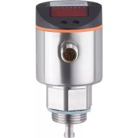
LR8000 - Sensor IFM - Free user manual and instructions
Find the device manual for free LR8000 IFM in PDF.


User questions about LR8000 IFM
0 question about this device. Answer the ones you know or ask your own.
Ask a new question about this device
Download the instructions for your Sensor in PDF format for free! Find your manual LR8000 - IFM and take your electronic device back in hand. On this page are published all the documents necessary for the use of your device. LR8000 by IFM.
USER MANUAL LR8000 IFM
CE
Operating instructions Electronic level sensor
LR8000
UK

Contents
1 Preliminary note....4
1.1 Symbols used .... 4
2 Safety instructions ....4
3 Items supplied....5
4 Functions and features....7
4.1 Operation with single probe....7
4.2 Operation with coaxial probe....7
4.3 Applications ....8
4.3.1 Restriction of the application area 8
5 Function....9
5.1 Measuring principle 9
5.2 Features of the unit....10
5.2.1 Easy set-up....10
5.2.2 Display functions ...... 10
5.2.3 Switching functions....10
5.2.4 Offset for indicating the real level in the tank....11
5.2.5 Probes for different tank heights.... 11
5.2.6 Safe state 11
5.2.7 Binary mode 12
5.3 IO-Link....13
6 Installation....14
6.1 Installation location / environment 14
6.1.1 Unit with single probe 14
6.1.2 Unit with coaxial probe 17
6.2 Installation of the probe ....18
6.2.1 Installation of the rod 18
6.2.2 Installation of the coaxial pipe 19
6.3 Shortening of the probe ....20
6.3.1 How to shorten the rod and to determine its length L....20
6.3.2 Shortening of the coaxial pipe 20
6.3.3 Determination of the rod length L when coaxial probes are used.....21
6.4 Installation of the unit with single probe....21
6.4.1 Installation in closed metal tanks (without flange plate) 22
6.4.2 Installation in closed metal tanks (with flange plate) 22
6.4.3 Installation in open tanks....23
6.4.4 Installation in plastic tanks....24
6.5 Installation of the unit with coaxial probe in the tank 25
6.6 Alignment of the sensor housing 25
7 Electrical connection....26
8 Operating and display elements 27
9 Menu....28
9.1 Menu structure / switching mode (bin = OFF) 28
9.2 Menu structure / binary mode (bin = on)....29
9.3 Explanation of the menu 30
10 Parameter setting ....31
10.1 Parameter setting in general 31
10.2 Basic settings (unit on delivery)....33
10.2.1 Entering the probe length 33
10.2.2 Setting to the medium....33
10.2.3 Entering the type of probe used 33
10.3 Configuration of the display 34
10.4 Selecting the evaluation mode ....34
10.5 Offset setting....34
10.6 Setting of output signals 34
10.6.1 Setting of the output function....34
10.6.2 Set the switching limits (hysteresis function)....35
10.6.3 Set the switching limits (window function) 35
10.6.4 Setting of the switch-off delay....35
10.6.5 Response of the outputs in case of a fault 35
10.6.6 Setting of the delay time after signal loss....35
10.7 Reset all parameters to factory setting 36
10.8 Changing basic settings 36
10.8.1 Re-enter the probe length....36
10.8.2 Setting to another medium 36
10.8.3 New entering of the type of probe used....36
11 Operation 37
11.1 Operating indicators ....37
11.2 Read the set parameters ....37
11.3 Changing the display unit in the Run mode 37
11.4 Error indications 38
11.5 Output response in different operating states....39
12 Technical data and scale drawing....39
12.1 Setting ranges 39
13 Servicing....40
14 Applications....41
14.1 Storage tanks / level monitoring ....41
14.2 Storage tank 42
14.3 Pumping station....43
15 Factory setting 44
1 Preliminary note
1.1 Symbols used
▶ Instructions
▷ Reaction, result
[...] Designation of keys, buttons or indications
→ Cross-reference

Important note
Non-compliance may result in malfunction or interference.

Information
Supplementary note.
2 Safety instructions
- The device described is a subcomponent for integration into a system.
- The manufacturer of the system is responsible for the safety of the system.
- The system manufacturer undertakes to perform a risk assessment and to create a documentation in accordance with legal and normative requirements to be provided to the operator and user of the system. This documentation must contain all necessary information and safety instructions for the operator, the user and, if applicable, for any service personnel authorised by the manufacturer of the system.
- Read this document before setting up the product and keep it during the entire service life.
- The product must be suitable for the corresponding applications and environmental conditions without any restrictions.
- Only use the product for its intended purpose (→ Functions and features).
- Only use the product for permissible media (→ Technical data).
- If the operating instructions or the technical data are not adhered to, personal injury and/or damage to property may occur.
- The manufacturer assumes no liability or warranty for any consequences caused by tampering with the product or incorrect use by the operator.
• Installation, electrical connection, set-up, operation and maintenance of the unit must be carried out by qualified personnel authorised by the machine operator. - Protect units and cables against damage.
- The unit may cause radio interference in domestic areas. If interference occurs, the user must take appropriate remedial actions.
- The unit complies with the standard EN 61000-6-4 and is a class A product. The radiated energy of the microwaves is, for example, much below that of mobile phones. According to the current state of science the operation of the unit can be classified to be harmless to human health.
3 Items supplied
• Level sensor LR8000
- Operating instructions
In addition, the following is necessary for installation and operation:
• 1 rod (for operation of the unit with single probe→4.1)
- plus 1 coaxial pipe (for operation of the unit with coaxial probe → 4.2)
- mounting material (if necessary, a launching plate → 4.1)
The following components are available as accessories:
| Rods | Length (cm / inch) | Order number |
| 15 / 5.9 | E43225 | |
| 24 / 9.5 | E43203 | |
| 30 / 11.8 | E43226 | |
| 45 / 17.7 | E43204 | |
| 50 / 19.7 | E43227 | |
| 70 / 27.6 | E43205 | |
| 100 / 39.4 | E43207 | |
| 120 / 47.2 | E43208 | |
| 140 / 55.1 | E43209 | |
| 160 / 63.0 | E43210 |
| Coaxial pipes with process connection G3/4 | Length (cm / inch) | Order number |
| 24 / 9.5 | E43211 | |
| 30 / 11.8 | E43228 | |
| 45 / 17.7 | E43212 | |
| 50 / 19.7 | E43229 | |
| 70 / 27.6 | E43213 | |
| 100 / 39.4 | E43214 | |
| 120 / 47.2 | E43215 | |
| 140 / 55.1 | E43216 | |
| 160 / 63.0 | E43217 | |
| Coaxial pipes with process connection 3/4" NPT | Length (cm / inch) | Order number |
| 45 / 17.7 | E43218 | |
| 70 / 27.6 | E43219 | |
| 100 / 39.4 | E43220 | |
| 120 / 47.2 | E43223 | |
| 140 / 55.1 | E43224 | |
| 160 / 63.0 | E43221 | |
| Flange plates | Size / process connection | Order number |
| 73 - 90 / G3/4 | E43201 | |
| 65 - 80 / G3/4 | E43202 |

Only use rods and coaxial pipes from ifm electronic gmbh. The optimum function is not ensured when using components from other manufacturers.
4 Functions and features
The unit continuously detects the level in tanks and generates output signals according to the parameter settings.
4 switching outputs are available. They can be set separately.
4.1 Operation with single probe
The single probe is made up of one individual rod. Operation with single probe is suited for the detection of aqueous media, in particular of heavily soiled aqueous media.

For the correct function with single probe, the unit needs a large enough metal launching plate. It is necessary for transferring the microwave pulse to the tank with optimum transmission power.
The flange plates that are available as accessories are not sufficient as launching plates. Only use accessories indicated as "launching plate". Suitable launching plates: ( → 6.4).
For installation in closed metal tanks, the tank lid serves as a launching plate. ▶ For installation in open metal tanks, tanks made of plastic or metal tanks with plastic lids a sufficiently large fixing plate, a metal plate or similar must be used ( → 6.4.3 / → 6.4.4).
For operation with single probe, minimum distances to tank walls, objects in the tank, bottom of the tank and further level sensors must be adhered to (→ 6.1.1).
4.2 Operation with coaxial probe
The coaxial probe is made up of an inner rod and an outer probe pipe (coaxial pipe). The rod is centred in the coaxial pipe by one or several spacers.
In case of operation with a coaxial probe media with a low dielectric constant (e.g. oil and oil-based media) are detected in addition to aqueous media.

No launching plate is required for operation with coaxial probe.
Furthermore, no minimum distances to tank walls and objects in the tank are required.
4.3 Applications
• Water, water-based media.
- Oils, oil-based media (only for operation with coaxial probe).
Application examples:
• Detection of coolant emulsion in a machine tool.
• Detection of cleaning liquid in a parts cleaning system.
- Monitoring of hydraulic oil in a hydraulic power unit (only for operation with coaxial probe).
4.3.1 Restriction of the application area

Incorrect measurements or signal loss may be caused by the following media:
- Highly absorbing surfaces (e.g. foam).
- Intensely bubbling surfaces.
- Media which are very inhomogeneous, separate from each other thus forming separation layers (e.g. oil layer on water).
▶ Check the function by performing an application test.
▶ Installation in a steady area ( → 6.1).
▷ In case of signal loss, the unit displays [E.033] and switches the outputs to a defined state ( → 11.5).
- The unit is not suitable for bulk materials (e.g. plastic granulates).
- If the unit is to be used in acids or alkalis, in hygienic areas or in electroplating applications: first check the compatibility of the product materials ( → Technical data sheet) with the media to be monitored.
- The unit is not suitable for applications where the probe is subjected to permanent and high mechanical stress (e.g. strongly moving viscous media or strongly flowing media).
- In case of operation with single probe: use preferably in metal tanks. When installed in plastic tanks, deterioration caused by electromagnetic interference may occur (noise immunity according to EN61000-6-2).
Corrective measures: → 6.4.4.
- When operating with a single probe and small tanks (probe lengths shorter than 200 mm and less than 300 mm distance to the tank wall), interference from the tank (resonances) may occur in rare cases.
Corrective measures: ( → 6.1.1).
- In case of operation with coaxial probe: not suitable for soiled or viscous media and media prone to formation of deposit.
Maximum viscosity: 500 MPa · s.
5 Function
5.1 Measuring principle

The unit operates to the principle of guided wave radar. It measures the level using electromagnetic pulses in the nanosecond range.
The pulses are transmitted by the sensor head and guided along the rod (fig. 5-1). When they hit the medium to be detected they are reflected and guided back to the sensor (fig. 5-2). The time between transmitting and receiving the pulse directly relates to the travelled distance (D) and the current level. The reference for distance measurement is the lower edge of the process connection.

The figures show the operation with single probe. In case of operation with a coaxial probe, the guided wave runs only along the inside of the coaxial pipe.
5.2 Features of the unit
5.2.1 Easy set-up
- When the unit is supplied with operating voltage for the first time, the probe length, the medium to be detected and the type of probe used must be entered. Then the unit is ready for operation ( → 10.2).
- If necessary, parameters for the output signals and optimisation of the monitoring functions can be set ( → 10.3 to → 10.5).
- All settings can also be carried out before installation of the unit.
- Reset to the factory settings is possible.
• Electronic lock can be set to prevent unintentional operations.
5.2.2 Display functions
The unit displays the current level, either in cm, inch or in percent of the final value of the measuring range. Factory setting: cm. The display unit is defined by programming ( → 10.3). In the Run mode, it can be temporarily switched between length indication (cm / inch) and percentage:
▶ Briefly press [Set].
▷ The selected unit is displayed for 30 s, the corresponding LED is lit. With each push of the button the display type is changed.
The set unit of measurement and the switching status of the outputs are indicated by LEDs.
5.2.3 Switching functions
The unit signals via 4 switching outputs OUT1... OUT4 that a set limit level has been reached or that the level is below the limit value. For each output the following switching functions can be selected:
• Hysteresis function / normally open (fig. 5-3): [OUx] = [Hno].
- Hysteresis function / normally closed (fig. 5.3): [OUx] = [Hnc].

First the set point (SPx) is set, then the reset point (rPx) with the requested difference.
- Window function / normally open (fig. 5-4): [OUx] = [Fno].
• Window function / normally closed (fig. 5-4): [OUx] = [Fnc].

The width of the window can be set by means of the difference between FHx and FLx. FHx = upper value, FLx = lower value.
| Fig. 5-3 | Fig. 5-4 |
 |  |
L = level; HY = hysteresis; FE = window
- For each switching output a switch-off delay of max. 60 s can be set (e.g. for especially long pump cycles).
5.2.4 Offset for indicating the real level in the tank
The zone between tank bottom and lower edge of the probe can be entered as offset value [OFS]. So display and switch points refer to the actual level.
5.2.5 Probes for different tank heights
- The unit can be installed in tanks of different sizes. Probes in different lengths are available. To adapt to the tank height, each probe can be shortened. The minimum probe length is 10 cm, the maximum probe length is 160 cm.
- Probe and housing can be rotated without restriction. This enables easy installation and orientation of the head of the unit after installation.
5.2.6 Safe state
• In case of a fault a safe state can be defined for each output.
- If a fault is detected or if the signal quality is below a minimum value, the outputs pass into the "safe state". For this case the response of the outputs can be set via the parameters [FOU1]... [FOU4].
- Temporary loss of signal caused e.g. by turbulence or foam formation can be suppressed by a delay time ( → 10.6.6 [dFo]). During the delay time the last measured value is frozen. If the measured signal is received again in sufficient strength within the delay time, the unit continues to work in normal operation.
If, however, it is not received again in sufficient strength within the delay time, the outputs pass into the safe state.

In case of heavy foam formation and turbulence, note the examples of how to create a steady area ( → 6.1.2).
5.2.7 Binary mode
In the binary mode the outputs OUT1... OUT4 indicate the level as a 8-4-2-1 binary code. Thus a quasi-analogue evaluation with a resolution of 15 steps (about 6.6 %) of the active zone (A) is available.
Below the probe and in the zone I2 the word 0000 is output (step 0). In the active zone (A) the steps 1...15 are passed through and the outputs switch to the shown states. If the active zone is exceeded (zone I1), the value of step 15 (word 1111) continues to be output.

For the zones A, I1 und I2 → Technical data sheet.
5.3 IO-Link
General information
This unit has an IO-Link communication interface which requires an IO-Link-capable module (IO-Link master) for operation.
The IO-Link interface enables direct access to the process and diagnostic data and provides the possibility to set the parameters of the unit during operation. In addition communication is possible via a point-to-point connection with a USB adapter cable.
Further information about IO-Link is available at www.ifm.com.
Device-specific information
You will find the IODDs necessary for the configuration of the IO-Link unit and detailed information about process data structure, diagnostic information and parameter addresses at www.ifm.com.
Parameter setting tools
You will find all necessary information about the required IO-Link hardware and software at www.ifm.com.
6 Installation
6.1 Installation location / environment
• Vertical installation from the top is preferred.
6.1.1 Unit with single probe
- For a safe function, the unit requires a launching plate ( → 6.4).
- The following minimum distances between the rod and tank walls, objects in the tank (B), tank bottom and other level sensors must be adhered to:

- For tank walls which are not straight, steps, supports or other structures in the tank a distance of 50 mm to the tank wall must be adhered to.
- When operating the unit in small tanks (probe lengths shorter than 200 mm and less than 300 mm distance to the tank wall), mount the unit off-centre (eccentrically) to prevent possible interference from tank resonances.
- For probe lengths > 70 cm the rod can be considerably deflected by movement of the medium. To avoid contacting the tank wall or other structures in the tank in such cases, the minimum distances should be increased.
Reference values:
| Probe length | Distance to the tank wall or structures in the tank |
| 70...100 cm | 100 mm |
| 100...160 cm | 180 mm |
- If the medium is strongly polluted, there is the risk that a bridge forms between the rod and the tank wall or structures in the tank. To avoid incorrect measurements: adhere to increased minimum distances depending on type and intensity of the soiling.
-
For installation in pipes:
-
The inside pipe diameter (d) must be at least 100 mm (fig. 6-1).
- ▶ If possible, mount the unit off-centre (eccentrically).
- Only install the unit in metal pipes.
- For installation in connection pieces:
- The diameter of the boss (d) must be at least 60 mm (fig. 6-2).
- The height of the boss (h) must not exceed 40 mm (fig. 6-2).

Although the unit can be installed in a boss, installation in a flat tank lid is recommended. A boss will impede the distribution of the microwaves.
| Fig. 6-1 | Fig. 6-2 |
 |  |
- Do not install the unit in the immediate vicinity of a fill opening (fig. 6-3). If possible, install a fill pipe (A) in the tank (fig. 6-4). Minimum distance between the fill pipe and the rod = 50 mm; higher for probe lengths > 70 cm and in case of heavy soiling ( → 6.1.1).


To avoid incorrect measurements in case of heavy foam formation and turbulence:
▶ If possible, install the sensor in a steady area.
Example how to create a steady area:
- Use of a coaxial probe (only for clean, low-viscosity media)
- Installation in bypass or still pipe (see fig. 6-5)
- Separation of the installation location by metal sheets / perforated sheets (without figure)

Min. diameter of the bypass and still pipe: d = 100 mm.
The upper access to the steady area (fig. 6-5: A / B) has to be above the maximum level. The lower access (fig. 6-5: C / D) or the area with perforated sheet etc. has to be below the minimum level. This ensures that neither foam nor turbulence impact the sensor zone. When perforated sheets or the like are used, soiling (e.g. by metal swarf, particles, ...) can also be avoided.
Fig. 6-5

6.1.2 Unit with coaxial probe
- No minimum distances to the tank wall and the baffles (B) are required.
- Minimum distance to the bottom of the tank: 10 mm.
- The vent hole (A) must not be covered by mounting elements or similar.
- Do not install the unit in the immediate vicinity of a fill opening. No water jets must enter into the holes of the coaxial pipe.

- Note in case of foam formation: the vent of the coaxial pipe must be above the maximum level. The lower edge of the coaxial pipe must be below the minimum level.
6.2 Installation of the probe
Rod and coaxial pipe are not included in the scope of delivery. They must be ordered separately ( → 3 Items supplied).
6.2.1 Installation of the rod
Fixing of the rod:
▶ Screw the rod to the unit and tighten it.

Recommended tightening torque: 4 Nm.
For ease of installation and removal the rod connection can be rotated without restriction. Even if rotated several times there is no risk of damage to the unit.

In case of high mechanical stress (strong vibration, moving viscous media) it may be necessary to secure the screw connection, e.g. by a screw retaining compound.

Substances such as screw retaining compounds may migrate into the medium.
Make sure that they are harmless.
When using mechanical means of securing (e.g. tooth lock washer), protruding edges must be avoided. They may cause interference reflection.
6.2.2 Installation of the coaxial pipe
This subchapter is only relevant if the unit is to be operated with a coaxial probe.

The coaxial pipe and the rod must be of the same end length. The coaxial pipe can be shortened ( → 6.3.2).
▶ Screw the rod to the unit and tighten it. Recommended tightening torque: 4 Nm.
▶ Slide the sensor seal (A) onto the thread.
▶ Slide the coaxial pipe (B) onto the rod. Carefully centre it and carefully move the rod through the centring piece (C) (for lengths > 140 cm through both centring pieces) of the coaxial pipe. Do not damage the centring pieces.
▶ Screw onto the sensor thread and tighten.

6.3 Shortening of the probe
6.3.1 How to shorten the rod and to determine its length L
The rod can be shortened to adapt the probe to different tank heights.

Ensure that the probe length is never below the minimum permissible probe length of 10 cm ( Lmin )! The unit does not support probe lengths below 10 cm. If shorter probes are used, measurement errors can occur.
Proceed as follows:
▶ Screw the rod to the unit.
▶ Mark the desired length (L) on the rod. The reference point is the lower edge of the process connection.
▶ Remove the rod from the unit.
▶ Shorten the rod at the mark.
▶ Remove all burrs and sharp edges.
▶ Screw the rod to the unit again and tighten it. Recommended tightening torque: 4 Nm.
▶ Precisely measure the probe length L, note the value. It must be entered during parameter setting of the unit ( → 10.2).

Lmin=10\ cm
6.3.2 Shortening of the coaxial pipe
The coaxial pipe and the rod must be of the same end length:


Fig. 6-6
▶ Remove fastening bracket and centring piece (A, B).
▶ Shorten the coaxial pipe to the requested length: LK = L + 9 mm.
▶ After shortening, at least one hole (C) for insertion of the fixing bracket has to be left.
▶ Remove all burrs and sharp edges.
▶ Insert centring piece (A) at the lower end of the pipe and attach it using the fixing bracket (B) at the lower hole (C).


LK = length of the coaxial pipe L = length of the rod from the lower edge of the process connection ( → 6.3.1)
6.3.3 Determination of the rod length L when coaxial probes are used
Only relevant if the rod length L ( → 6.3.1) is unknown:
▶ Measure the exact total length LK of the coaxial pipe ( → fig. 6-6, on the right).
▶ Deduct 9 mm from the total length of the coaxial pipe: LK - 9 mm = L
▶ Note down L. It must be entered during parameter setting of the unit ( → 10.2).
6.4 Installation of the unit with single probe

For the correct function when used with single probe, the unit needs a large enough metal launching plate. It is necessary for transferring the microwave pulse to the tank with optimum transmission power.
For installation in closed metal tanks, the tank lid serves as a launching plate (R in fig. 6-7 and 6-11). 2 ways of installation are possible:
- Screw in a G3/4 process connection in the tank lid ( → 6.4.1).
- Installation in the tank lid using a flange plate, e.g. for tanks with thin walls ( → 6.4.2).
Furthermore, installation in open tanks ( → 6.4.3) and plastic tanks is possible ( → 6.4.4).
6.4.1 Installation in closed metal tanks (without flange plate)
| Fig. 6-7 | Fig. 6-8 | Fig. 6-9 |
 |  |  |
▶ The lower edge of the process connection should be flush with the installation environment (fig. 6-7).
▶ Avoid non-flush installation (fig. 6-8).
▶ Use seals or washers (D in fig. 6-9) to reach the required height.
▶ For tanks with thick walls arrange for sufficiently deep recesses to ensure flush installation.
6.4.2 Installation in closed metal tanks (with flange plate)

Flange plates are not supplied. They must be ordered separately ( → 3 Items supplied).
| Fig. 6-10 | Fig. 6-11 |
 |  |
▶ Arrange for a bore hole in the tank lid. It must have a minimum diameter (d) to enable sufficient transfer of the measured signal to the probe (fig. 6-10). The diameter depends on the wall thickness of the tank lid:
| Wall thickness [mm] | 1...5 | 5...8 | 8...11 |
| Bore hole diameter [mm] | 35 | 45 | 55 |
▶ Install the flange plate with the flat surface showing to the tank and fix it with appropriate screws.

A seal (B in fig. 6-11) can be inserted between flange plate and tank. Some flange plates are supplied with a seal.
▶ Ensure cleanness and evenness of the sealing areas, especially if the tank is under pressure. Tighten the fixing screws sufficiently.
▶ Screw the unit into the flange plate using the process connection and tighten firmly.
▶ Make sure that the supplied sensor seal (A in fig. 6-11) is correctly positioned.
6.4.3 Installation in open tanks
For installation in open tanks, use a metal fixture to install the unit. It serves as a launching plate (R); minimum size: 150 x 150 mm for a square fixture, 150 mm diameter for a circular fixture ( → accessories).
▶ If possible, mount the unit in the middle of the fixture. The distance D2 must not be below 40 mm, higher for probe lengths > 70 cm and in case of heavy soiling ( → 6.1.1):

▶ The lower edge of the process connection should be flush with the installation environment (see fig. 6-7).
▶ Avoid non-flush installation (see fig. 6-8).
▶ Use seals or washers (see D in fig. 6-9) to reach the required height.
6.4.4 Installation in plastic tanks

To enable sufficient transfer of the measured signal, note in case of installation in plastic tanks or metal tanks with plastic lid:
▶ A drill hole with a minimum diameter of 150 mm must be applied to the plastic lid.
▶ For installation of the unit, a metal flange plate (= launching plate R) must be used which sufficiently covers the drill hole ( → accessories).
▶ Ensure the minimum distance (= 80 mm) between rod and tank wall, higher for probe lengths > 70 cm and in case of heavy soiling ( → 6.1.1).

When installed in plastic tanks, there may be deterioration caused by electromagnetic interference. Corrective measures:
- Apply a metal foil to the outside of the tank.
- Apply a shielding screen between the level sensor and other electronic units.
- Operation with coaxial probe efficiently protects the unit from electromagnetic interference. Please note the restrictions regarding the application area ( → 4.3).
6.5 Installation of the unit with coaxial probe in the tank
▶ Seal the process connection:
- For pipes with G 3/4 process connection: slide the supplied seal onto the thread of the coaxial pipe.
- For pipes with 3/4 NPT process connection: apply a suitable sealing material (e.g. Teflon tape).
▶ Screw the unit with the coaxial pipe into the tank and tighten it.
6.6 Alignment of the sensor housing

After installation, the sensor housing can be aligned. It can be rotated without restriction. Even if rotated several times there is no risk of damage to the unit.
7 Electrical connection

The unit must be connected by a qualified electrician.
The national and international regulations for the installation of electrical equipment must be adhered to.
Voltage supply according to SELV, PELV.
▶ Disconnect power.
▶ Connect the unit as follows:


| Pin / connection | Core colours | |
| for ifm sockets | for sockets according to DIN 47100 | |
| 1 L+ | brown | white |
| 2 OUT2 (switching output 2) | white | brown |
| 3 L- | blue | green |
| 4 OUT1 / IO-Link | black | yellow |
| 5 OUT3 (switching output 3) | grey | grey |
| 6 OUT4 (switching output 4) | pink | pink |
| 7 = not used | violet | blue |
Connector 8-pole on connector 4-pole available as accessories:
- order no. E11228 (Y connection cable)
- order no. E11627 (T splitter box)
8 Operating and display elements

| 1 to 8: Indicator LEDs |
| - LED 1: green = indication of the level in cm. |
| - LED 2: green = indication of the level in inch. |
| - LED 3: green = indication of the level in % of the final value of the measuring range. |
| - LED 4: not used. |
| - LED 5: yellow = output 4 is switched. |
| - LED 6: yellow = output 3 is switched. |
| - LED 7: yellow = output 2 is switched. |
| - LED 8: yellow = output 1 is switched. |
| 9: Alphanumeric display, 4 digits |
| - Indication of the current level. |
| - Operation and fault indication. |
| - Indication of the parameters and parameter values. |
| 10: Set button |
| - Setting of the parameter values (scrolling by holding pressed; incremental by pressing once). |
| - Change between cm/inch indication and percent indication in the normal operating mode (Run mode). |
| 11: Mode/Enter button |
| - Selection of the parameters and acknowledgement of the parameter values. |
9 Menu
9.1 Menu structure / switching mode (bin = OFF)

9.2 Menu structure / binary mode (bin = on)
9.3 Explanation of the menu
| SP1/rP1 | Upper / lower limit value for the level at which OUT1 switches. |
| FH1/FL1 | Upper / lower limit for the acceptable range (monitored by OUT1). |
| SP2/rP2 | Upper / lower limit value for the level at which OUT2 switches. |
| FH2/FL2 | Upper / lower limit for the acceptable range (monitored by OUT2). |
| SP3/rP3 | Upper / lower limit value for the level at which OUT3 switches. |
| FH3/FL3 | Upper / lower limit for the acceptable range (monitored by OUT3). |
| SP4/rP4 | Upper / lower limit value for the level at which OUT4 switches. |
| FH4/FL4 | Upper / lower limit for the acceptable range (monitored by OUT4). |
| OUx | Output function for OUTx:Switching signal for the level limit values: hysteresis function [H ..] or window function [F ..], either normally open [. no] or normally closed [. nc]. |
| OFS | Offset value for level measurement. |
| EF | Extended functions / opening of menu level 2. |
| rES | Restore factory setting. |
| dr1 | Switch-off delay for OUT1. The menu item is only active if OU1 = Hno or Hnc. |
| dr2 | Switch-off delay for OUT2. The menu item is only active if OU2 = Hno or Hnc. |
| dr3 | Switch-off delay for OUT3. The menu item is only active if OU3 = Hno or Hnc. |
| dr4 | Switch-off delay for OUT4. The menu item is only active if OU4 = Hno or Hnc. |
| FOUx | Response of OUTx in case of a fault. |
| dFo | Delay time for switching response OUTx in case of a fault. |
| Uni | Unit of measurement (cm or inch). |
| SELd | Type of indication. |
| LEnG | Probe length. |
| MEdl | Medium to be detected. |
| Prob | Type of probe used (single probe or coaxial probe). The menu item is only active if MEdl = HIGH. |
| bin | Changing between switching mode and binary mode. |
10 Parameter setting
During parameter setting the unit remains in the operating mode internally. It continues to monitor with the existing parameters until the parameter setting has been completed.
10.1 Parameter setting in general
3 steps must be taken for each parameter setting:
| 1 | Select parameter ▶ Press [Mode/Enter] until the requested parameter is displayed. |  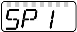 |
| 2 | Set parameter value ▶ Press [SET] and keep it pressed. ▷ Current setting value of the parameter flashes for 5 s. ▷ After 5 s: setting value is changed: incrementally by pressing the button once or continuously by keeping the button pressed. |   170 170 |
| Numerical values are incremented continuously. For reducing the value: let the display move to the maximum setting value. Then the cycle starts again at the minimum setting value. | ||
| 3 | Acknowledge parameter value ▶ Briefly press [Mode/Enter]. ▷ The parameter is displayed again. The new setting value is saved. |  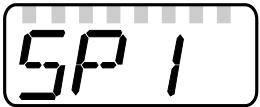 |
| Setting of other parameters: ▶ Start again with step 1. | ||
| Finishing the parameter setting: ▶ Press [Mode/Enter] several times until the current measured value is displayed or wait for 30 s. ▷ The unit returns to the operating mode. | ||

If [S. Loc] is displayed → 11.1 Operating indicators.
- Change from menu level 1 to menu level 2:
| ▶ Press [Mode/Enter] until [EF] is displayed. |  |
| ▶ Briefly press [Set]. ▷ The first parameter of the submenu is displayed (here: [res]). |  |
- Locking / unlocking
The unit can be locked electronically to prevent unintentional settings:
| ▶ Make sure that the unit is in the normal operating mode. ▶ Press [Mode/Enter] + [Set] for 10 s. ▷ [Loc] is displayed. | 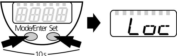 |
| During operation: > [Loc] is briefly displayed if you try to change parameter values. | |
| For unlocking: ▶ Press [Mode/Enter] + [Set] for 10 s. ▷ [uLoc] is displayed. |  |
On delivery: not locked.
- Timeout:
If no button is pressed for 30 s during parameter setting, the unit returns to the operating mode with unchanged values.
10.2 Basic settings (unit on delivery)
On delivery of the unit, you must first enter the basic settings. The complete parameter setting menu cannot be accessed before this.

Malfunctions may occur if wrong basic settings are entered.
10.2.1 Entering the probe length
| ▶ Apply operating voltage. ▷ The initial display ≡≡≡ is shown. ▶ Select [LEnG], press [SET] for 5 s. ▷ [nonE] is displayed. ▶ Enter the probe length in cm. Remarks on the determination of the probe length → 6.3.1 (single probes) or → 6.3.3 (coaxial probes). ▶ Briefly press [Mode/Enter]. | LEnG |
10.2.2 Setting to the medium
| ▶ Select [MEdI], press [Set] for 5 s. ▷ [nonE] is displayed. ▶ Set the requested value:- [HIGH] for water and water-based media.- [LOW] for oils and oil-based media. Note: In case of doubt, carry out an application test to ensure the setting which is best for your medium. | MedI |
10.2.3 Entering the type of probe used
| ▶ Select [Prob], press [Set] for 5 s. ▷ [nonE] is displayed. ▶ Set the requested value:- [rod] for single probe.- [COAX] for coaxial probe.• The detection of water and water-based media is possible with the single probe as well as with the coaxial probe.• The detection of oils and oil-based media is only possible with the coaxial probe. Therefore, the parameter [Prob] is preset to [COAX] in case of the setting [MEdI] = [LOW]; the value [rod] is not available. | Prob |
Then the unit changes to the operating mode. For further parameter setting the menu can be opened. The parameters [LEnG], [MEdI] and [Prob] can be accessed and modified just like all other parameters.
10.3 Configuration of the display
| ▶ Select [Uni] and set the unit of measurement: [cm], [inch]. Factory setting: cm. ▶ Select [SELd] and set type of indication:- [L] = The level is indicated in cm or inch.- [L%] = The level is indicated in percent of the final value of the measuring range.- [OFF ] = The display is switched off in the operating mode. When one of the buttons is pressed, the current measured value is displayed for 30 s. The LEDs remain active even if the display is deactivated. |  |
10.4 Selecting the evaluation mode
| ▶ [Select [bin] and set the mode:[OFF] = switching mode (= on delivery),[on] = binary mode. The switching parameters SPx, rPx, OUx and drx are not available in the binary mode. |  |
10.5 Offset setting
| ▶ Select [OFS] and enter the distance between bottom of the tank and lower edge of the probe. Afterwards, display and switch points refer to the real level. Factory setting: [OFS] = 0. Note: Set [OFS] before setting the switching limits (SPx/FHx, rPx/FLx). Otherwise, the switching limits shift by the value of the set offset. |  |
10.6 Setting of output signals
10.6.1 Setting of the output function
| ▶ Select [OU1] ... [OU4] and set the switching function:[Hno] = hysteresis function/NO,[Hnc] = hysteresis function/NC,[Fno] = window function/NO,[Fnc] = window function/NC. Note: If the upper switch point is used as an overflow protection, the setting OUx = Hnc (NC function) is recommended. The principle of normally closed operation ensures that wire break or cable break is also detected. |  |
10.6.2 Set the switching limits (hysteresis function)
| ▶ Make sure that the function [Hno] or [Hnc] is set for the corresponding output [OUx]. ▶ Select [SP1] ... [SP4] and set the value at which the output switches. | SP1... SP4 |
| ▶ Select [rP1] ... [rP4] and set the value at which the output is reset. rPx is always smaller than SPx. The unit only accepts values which are lower than the value for SPx. | rP1...rP4 |
10.6.3 Set the switching limits (window function)
| ▶ Make sure that for [OUx] the function [Fno] or [Fnc] is set. ▶ Select [FH1] ... [FH4] and set the upper limit of the acceptable range. | FH1... FH4 |
| ▶ Select [FL1] ... [FL4] and set the lower limit of the acceptable range. FLx is always lower than FHx. The unit only accepts values which are lower than the value for FHx. | FL1... FL4 |
10.6.4 Setting of the switch-off delay
| ▶ Select [dr1] ... [dr4] and set the value between 0.2 and 60 s. At 0.0 (= factory setting) the delay time is not active. The switch-off delay is only active if hysteresis has been set as switching function (OUx = Hno or Hnc). | dr-1...dr-4 |
10.6.5 Response of the outputs in case of a fault
| ▶ Select [FOU1] ... [FOU4] and set the value:[on] = output switches ON in case of a fault. [OFF] = output switches OFF in case of a fault. Factory setting: [FOU1] ... [FOU4] = [OFF]. Faults: faulty hardware, too low a signal quality, untypical level curve. Overflow is not considered to be a fault. | FOU1... FOU4 |
10.6.6 Setting of the delay time after signal loss
| ▶ Select [dFo] and set a value between 0.2 and 5.0 s. At 0.0 (= factory setting) the delay time is not active. Mind the dynamics of your application. In case of fast level changes it is recommended to adapt the value step by step. | dFo |
10.7 Reset all parameters to factory setting
| ▶ Select [rES], then press [Set] and keep it pressed until [----] is displayed. ▶ Briefly press [Mode/Enter]. ▷ The unit reboots and the factory settings are restored. Note: On delivery the unit is not operational. First, the basic settings must be entered (→ 10.2). | r-ES |
10.8 Changing basic settings
Required after changes to the probe or to the application area.
10.8.1 Re-enter the probe length
| ▶ Change to menu level 2▶ Select [LEnG] and set probe length L. Note the set unit of measurement (cm or inch). Step increment: 0.5 cm / 0.2 inch. Remarks on the determination of the probe length:▶ Note the remarks → 6.3.1 (single probes) or → 6.3.3 (coaxial probes). ▶ Briefly press [Mode/Enter]. Note: After changing the probe length, the values for OFS and the switching limits must also be reviewed / re-entered. | LEnG |
10.8.2 Setting to another medium
| ▶ Select [MEdI] and set the value:- [HIGH] for water and water-based media.- [LOW] for oils and oil-based media. Note: In case of doubt, carry out an application test to ensure the setting which is best for your medium. | MEDI |
10.8.3 New entering of the type of probe used
| ▶ Select [Prob] and set the value:- [rod] for single probe.- [COAX] for coaxial probe.• The detection of water and water-based media is possible with the single probe as well as with the coaxial probe.• The detection of oils and oil-based media is only possible with the coaxial probe. Therefore, the parameter [Prob] is not available in case of the setting [MEdI] = [LOW] (the value [COAX] is preset). | Prob |
11 Operation
After power on, the unit is in the Run mode (= normal operating mode). It carries out its measurement and evaluation functions and generates output signals according to the set parameters.
11.1 Operating indicators
| [---] continuously | Initialisation phase after power on. |
| Numerical value + LED 1 | Current level in cm. |
| Numerical value + LED 2 | Current level in inch. |
| Numerical value + LED 3 | Current level in % of the final value of the measuring range. |
| LED 5 ... LED 8 | Switching status of the corresponding output. |
| [----] | Level below the active zone. |
| [FULL] + numerical value alternately | Level has reached or exceeded the maximum measuring range (= overflow warning). |
| ≡≡≡≡ | On delivery the unit is not operational. Basic settings required (→ 10.2). |
| [Loc] | Unit electronically locked; parameter setting impossible. For unlocking press the two setting buttons for 10 s. |
| [uLoc] | Unit is unlocked / parameter setting is possible again. |
| [S. Loc] | If [S. Loc] is displayed when an attempt is made to modify a parameter value, either an IO-Link communication is active (temporary locking) or the sensor is permanently locked via software. This locking can only be removed with a parameter setting software. |
11.2 Read the set parameters
▶ Briefly press [Mode/Enter] to scroll the parameters.
▶ Press [Set] briefly to indicate the corresponding parameter value for about 30 s. After another 30 s the unit returns to the Run mode.
11.3 Changing the display unit in the Run mode
(= switching between length indication (cm / inch) and percentage).
▶ Briefly press [Set] in the Run mode.
▷ The selected unit is displayed for 30 s, the corresponding LED is lit. With each push of the button the display type is changed.
11.4 Error indications
| Possible cause | Recommended measures | |
| [E.000] | Fault in the electronics. | Replace the unit. |
| [E.031] | Probe detached from the unit; possibly incorrect setting of the probe length. | Check whether the probe is still attached to the unit. Check the parameter [LEnG]. |
| [E.033] | Measurement disturbed by heavy foam formation or turbulence. | • Install the unit in a still pipe or bypass.• Set or increment [dFo] (→ 10.6.6). |
| Measurement disturbed by separation layers (e.g. oil layer on water). | Remove the oil layer by suction, stir the medium, verify the composition. | |
| Rod or process connection soiled. | Clean the rod and the process connection, carry out a reset.* | |
| Installation conditions were not adhered to. | Observe the notes in "Installation" (→ 6). | |
| Probe length, type of probe or sensitivity (setting to the medium) is incorrect. | Correct the settings (→ 10.2), then carry out a reset.* | |
| [SCx] | Flashing: short circuit in switching output x. | Remove the short circuit. |
| [SC] | Flashing: short circuit in all switching outputs. | Remove the short circuit. |
| [PARA] | Faulty data set | Reset to factory settings (→ 10.7). |
* Carry out a reset (power off and on again) after rectifying the fault to reset the error message.
11.5 Output response in different operating states
| OUT1... OUT4 | |
| Initialisation | OFF |
| Normal operation | according to the level and the setting of the output function (bin, OU1... OU4) |
| Fault (E.0xx) | OFF for FOUx = OFF;ON for FOUx = on |
| cm | inch | |||
| min | max | min | max | |
| L (probe length) | 10 | 160 | 4.0 | 63 |
| A (active zone) | 6 (4) | L - 4 (L - 6) | 2.4 (1.6) | L - 1.6 (L - 2.4) |
| I1 (inactive zone 1) | 3 | 1.2 | ||
| I2 (inactive zone 2) | 1 (3) | 0.4 (1.2) | ||
The values in brackets apply to the setting [MEdI] = [LOW] (setting for the detection of oils and oil-based media).
12 Technical data and scale drawing

Technical data and scale drawing at www.ifm.com.
12.1 Setting ranges
| [LEnG] | cm | inch |
| Setting range | 10...160 | 4.0...63 |
| Step increment | 0.5 | 0.2 |
| [OFS] | cm | inch |
| Setting range | 0...100 | 0...39.4 |
| Step increment | 0.5 | 0.2 |
The setting ranges for the switching limits (SPx, rPx, FHx, FLx) depend on the probe length (L). In general the following applies:
| cm | inch | |||
| min | max | min | max | |
| SPx / FHx | 1.5 (3.5) | L - 3 | 0.6 (1.4) | L - 1.2 |
| rPx / FLx | 1.0 (3.0) | L - 3.5 | 0.4 (1.2) | L - 1.4 |
| Step increment | 0.5 | 0.2 | ||
The values apply if [OFS] = 0. The values in brackets apply to the setting [MEdI] = [LOW] (setting for the detection of oils and oil-based media).
- rPx (FLx) is always smaller than SPx (FHx).
If the value for SPx (FHx) is reduced to a value ≤ rPx (FLx), the position of rPx (FLx) also shifts. - If rPx (FLx) and SPx (FHx) are close together (approx. 3 x step increment), rPX (FLx) is changed automatically when SPx (FHx) is increased.
- If there is a greater distance between rPx (FLx) and SPx (FHx), rPx (FLx) maintains the set value even if SPx (FHx) is increased.
13 Servicing
▶ Keep the process connection free of deposits and foreign bodies.
▶ In case of heavy soiling: clean the process connection and the probe at regular intervals.
In case of longer operation separation layers can form in the medium (e.g. oil on water). This applies especially to still pipes or bypasses.
▶ Remove separation layers at regular intervals.
▶ Ensure that the vent hole (at the upper end of the coaxial pipe) remains free.
▶ Keep the interior of the coaxial pipe free from foreign bodies and soiling.
14 Applications
14.1 Storage tanks / level monitoring
Level monitoring with evaluation in the binary mode
- Menu setting: bin = on.
- The settings for SPx, rPx, drx and OUx are not effective.

XX. X = display value
A = binary value
P1: position 1, e.g. maximum value reached; P2: position 2, e.g. upper preset value reached;
P3: position 3, e.g. lower preset value reached; P4: position 4, e.g. minimum value reached
The binary mode corresponds to an analogue evaluation with a resolution of 6.6 % of the active zone or 4 bits.
In the evaluation electronics (PLC etc.) no analogue input is used, the analogue value is already available in digital form (8-4-2-1 binary code).
14.2 Storage tank
Level control and min / max monitoring with 4 switching outputs.
Replaces 4 float switches.
| Configuration of the switching outputs 1 ... 4 (bin = OFF) | |
| SP1 | Maximum value exceeded → alarm. |
| OU1 | Hysteresis function, normally closed (Hnc). |
| SP2 | Upper preset value reached → finish refilling. |
| OU2 | Hysteresis function, normally open (Hno). |
| SP3 | Below lower preset value → start refilling. |
| OU3 | Hysteresis function, normally closed (Hnc). |
| SP4 | Below min. value → alarm. |
| OU4 | Hysteresis function, normally open (Hno). |
| rP1...rP4 | Each slightly below SPx to suppress wave movements (factory setting). |

XX. X = display value
- If the level is below SP1, the output is switched. If the level is above SP1 or if there is a wire break, output 1 switches OFF (alarm message "overflow/wire break").
- If the level reaches SP2, output 2 switches (upper preset value reached, finish refilling).
- If the level is below SP3, output 3 switches (below lower preset value, start refilling).
- If the level is above SP4, the output is switched. If the level is below SP4 or if there is a wire break, output 4 switches OFF (alarm message "below min. value / wire break").
14.3 Pumping station
Empty the tank / overflow protection with 3 switching outputs.
Replaces 3 float switches.
| Configuration of the switching outputs 1 ... 3 (bin = OFF) | |
| SP1 | Maximum value exceeded → alarm. |
| OU1 | Hysteresis function, normally closed (Hnc). |
| SP2 | Upper value exceeded → submersible pump ON. |
| OU2 | Hysteresis function, normally open (Hno). |
| SP3 | Lower value reached → submersible pump OFF. |
| OU3 | Hysteresis function, normally closed (Hnc). |
| rP1...rP3 | Each slightly below SPx to suppress wave movements (= factory setting). |

XX. X = display value; A = empty the tank; B = overflow protection
- If the level is below SP1, the output is switched. If the level is above SP1 or if there is a wire break, output 1 switches OFF (alarm message "overflow / wire break").
- If the level exceeds SP2, output 2 switches (upper value exceeded, submersible pump ON).
- If the level is below SP3, output 3 switches (lower value reached, submersible pump OFF).
15 Factory setting
| Factory setting | User setting | |
| SP1 / FH1 | 25% SP/FHmax | |
| rP1 / FL1 | 25% rP/FLmax | |
| OU1 | Hno | |
| SP2 / FH2 | 50% SP/FHmax | |
| rP2 / FL2 | 50% rP/FLmax | |
| OU2 | Hno | |
| SP3 / FH3 | 75% SP/FHmax | |
| rP3 / FL3 | 75% rP/FLmax | |
| OU3 | Hno | |
| SP4 / FH4 | 100% SP/FHmax | |
| rP4 / FL4 | 100% rP/FLmax | |
| OU4 | Hnc | |
| OFS | 0.0 | |
| dr1 | 0.0 | |
| dr2 | 0.0 | |
| dr3 | 0.0 | |
| dr4 | 0.0 | |
| FOU1 | OFF | |
| FOU2 | OFF | |
| FOU3 | OFF | |
| FOU4 | OFF | |
| dFo | 0 | |
| Uni | cm | |
| SELd | L | |
| LEnG | nonE | |
| MEdl | nonE | |
| Prob | nonE | |
| bin | OFF |
SP/FHmax = LEnG value minus 3.
rP/FLmax = LEnG value minus 3.5.
When the LEnG value is entered, the program calculates the basic setting.
- 1 PRELIMINARY NOTE
- 1.1 SYMBOLS USED
- 2 SAFETY INSTRUCTIONS
- 3 ITEMS SUPPLIED
- 4 FUNCTIONS AND FEATURES
- 4.1 OPERATION WITH SINGLE PROBE
- 4.2 OPERATION WITH COAXIAL PROBE
- 4.3 APPLICATIONS
- 4.3.1 RESTRICTION OF THE APPLICATION AREA
- 5 FUNCTION
- 5.1 MEASURING PRINCIPLE
- 5.2 FEATURES OF THE UNIT
- 5.2.1 EASY SET-UP
- 5.2.2 DISPLAY FUNCTIONS
- 5.2.3 SWITCHING FUNCTIONS
- 5.2.4 OFFSET FOR INDICATING THE REAL LEVEL IN THE TANK
- 5.2.5 PROBES FOR DIFFERENT TANK HEIGHTS
- 5.2.6 SAFE STATE
- 5.2.7 BINARY MODE
- 5.3 IO-LINK
- 6 INSTALLATION
- 6.1 INSTALLATION LOCATION / ENVIRONMENT
- 6.1.1 UNIT WITH SINGLE PROBE
- 6.1.2 UNIT WITH COAXIAL PROBE
- 6.2 INSTALLATION OF THE PROBE
- 6.2.1 INSTALLATION OF THE ROD
- 6.2.2 INSTALLATION OF THE COAXIAL PIPE
- 6.3 SHORTENING OF THE PROBE
- 6.3.1 HOW TO SHORTEN THE ROD AND TO DETERMINE ITS LENGTH L
- 6.3.2 SHORTENING OF THE COAXIAL PIPE
- 6.3.3 DETERMINATION OF THE ROD LENGTH L WHEN COAXIAL PROBES ARE USED
- 6.4 INSTALLATION OF THE UNIT WITH SINGLE PROBE
- 6.4.1 INSTALLATION IN CLOSED METAL TANKS (WITHOUT FLANGE PLATE)
- 6.4.2 INSTALLATION IN CLOSED METAL TANKS (WITH FLANGE PLATE)
- 6.4.3 INSTALLATION IN OPEN TANKS
- 6.4.4 INSTALLATION IN PLASTIC TANKS
- 6.5 INSTALLATION OF THE UNIT WITH COAXIAL PROBE IN THE TANK
- 6.6 ALIGNMENT OF THE SENSOR HOUSING
- 7 ELECTRICAL CONNECTION
- 8 OPERATING AND DISPLAY ELEMENTS
- 9 MENU
- 9.1 MENU STRUCTURE / SWITCHING MODE (BIN = OFF)
- 9.2 MENU STRUCTURE / BINARY MODE (BIN = ON)
- 9.3 EXPLANATION OF THE MENU
- 10 PARAMETER SETTING
- 10.1 PARAMETER SETTING IN GENERAL
- 10.2 BASIC SETTINGS (UNIT ON DELIVERY)
- 10.2.1 ENTERING THE PROBE LENGTH
- 10.2.2 SETTING TO THE MEDIUM
- 10.2.3 ENTERING THE TYPE OF PROBE USED
- 10.3 CONFIGURATION OF THE DISPLAY
- 10.4 SELECTING THE EVALUATION MODE
- 10.5 OFFSET SETTING
- 10.6 SETTING OF OUTPUT SIGNALS
- 10.6.1 SETTING OF THE OUTPUT FUNCTION
- 10.6.2 SET THE SWITCHING LIMITS (HYSTERESIS FUNCTION)
- 10.6.3 SET THE SWITCHING LIMITS (WINDOW FUNCTION)
- 10.6.4 SETTING OF THE SWITCH-OFF DELAY
- 10.6.5 RESPONSE OF THE OUTPUTS IN CASE OF A FAULT
- 10.6.6 SETTING OF THE DELAY TIME AFTER SIGNAL LOSS
- 10.7 RESET ALL PARAMETERS TO FACTORY SETTING
- 10.8 CHANGING BASIC SETTINGS
- 10.8.1 RE-ENTER THE PROBE LENGTH
- 10.8.2 SETTING TO ANOTHER MEDIUM
- 10.8.3 NEW ENTERING OF THE TYPE OF PROBE USED
- 11 OPERATION
- 11.1 OPERATING INDICATORS
- 11.2 READ THE SET PARAMETERS
- 11.3 CHANGING THE DISPLAY UNIT IN THE RUN MODE
- 11.4 ERROR INDICATIONS
- 11.5 OUTPUT RESPONSE IN DIFFERENT OPERATING STATES
- 12 TECHNICAL DATA AND SCALE DRAWING
- 12.1 SETTING RANGES
- 13 SERVICING
- 14 APPLICATIONS
- 14.1 STORAGE TANKS / LEVEL MONITORING
- 14.2 STORAGE TANK
- 14.3 PUMPING STATION
- 15 FACTORY SETTING
Brand : IFM
Model : LR8000
Category : Sensor