CAPXM - Video Intercom LIFT-MASTER - Free user manual and instructions
Find the device manual for free CAPXM LIFT-MASTER in PDF.

| Product Type | Video Intercom |
| Brand | LIFT-MASTER |
| Model | CAPXM |
| Category | Video Intercom |
| Power Supply | 24 V DC, 60 W min, Class 2, Efficiency Level VI |
| Power Consumption | 0.75 A typical, 3 A max at 15 V DC |
| Network Connectivity | Ethernet 10/100 (RJ45) and Wi-Fi 802.11b/g/n @ 2.4 GHz |
| Wi-Fi Security | WPA3 Personal, WPA2 Personal (AES) |
| Wireless Protocols | Security+ 2.0, Wiegand 26/30/37 bits, MiFare 32 bits |
| Integrated Camera | 1080p, 135° diagonal field of view |
| Local Video Storage | Up to 1000 events of 30 seconds each |
| Number of Access Points | Up to 2 doors/gates |
| Resident Capacity | 50,000 |
| Event History | 50,000 events |
| Operating Temperature Range | -29°C to 54°C |
| Storage Temperature Range | -40°C to 65°C |
| Housing Material | Carbon steel and aluminum |
| Warranty | 2 years |
| Spare Parts Available | Camera, logic board, microphone, speaker, power supply, etc. |
| Compatible Accessories | RFID readers, Wiegand keypads, Wi-Fi antennas, etc. |
Frequently Asked Questions - CAPXM LIFT-MASTER
User questions about CAPXM LIFT-MASTER
0 question about this device. Answer the ones you know or ask your own.
Ask a new question about this device
Download the instructions for your Video Intercom in PDF format for free! Find your manual CAPXM - LIFT-MASTER and take your electronic device back in hand. On this page are published all the documents necessary for the use of your device. CAPXM by LIFT-MASTER.
USER MANUAL CAPXM LIFT-MASTER
Safety Symbol and Signal Word Review
When you see these Safety Symbols and Signal Words on the following pages, they will alert you to the possibility of serious injury or death if you do not comply with the warnings that accompany them. The hazard may come from something mechanical or from electric shock. Read the warnings carefully.
When you see this Signal Word on the following pages, it will alert you to the possibility of damage to your property or product if you do not comply with the cautionary statements that accompany it. Read them carefully.

WARNING
MECHANICAL

WARNING
ELECTRICAL

CAUTION


WARNING
To reduce the risk of SEVERE INJURY or DEATH:
- Disconnect power at the fuse box BEFORE proceeding.
- To AVOID damaging gas, power or other underground utility lines, contact underground utility locating companies BEFORE digging.
- ALL electrical connections MUST be made by a qualified individual.
- ALL power and control wiring MUST be run in separate conduit.
- All power wiring should be on a dedicated circuit and well protected. The location of the power disconnect should be visible and clearly labeled.
- The CAPXM shall be installed in accordance with the National Electrical Code and all local codes.
To protect against fire and electrocution:
- Disconnect power BEFORE installing or servicing CAPXM.
- NEVER connect a keypad/reader or lock to doors without first consulting the applicable fire code.
- You MUST consult with, and get approval from, local fire officials BEFORE installing locks or devices on ANY doors that may be fire exits.
- Use of egress push buttons may not be legal. Single action exits may be required.
- ALWAYS obtain proper permits and approvals in writing BEFORE installing equipment.

WARNING
DO NOT INSTALL THE SYSTEM IN THE FAIL SECURE MODE UNLESS PERMITTED BY THE LOCAL AUTHORITY HAVING JURISDICTION. Doing so may cause interference with the operation of panic hardware.

WARNING: This product can expose you to chemicals including lead, which are known to the State of California to cause cancer or birth defects or other reproductive harm. For more information go to www.P65Warnings.ca.gov.
INTRODUCTION
CAPXM Overview 4
Control Board Overview 5
Door Board Overview 6
Carton Inventory 7
Tools Needed 7
Dimensions 8
System Specifications 8
Wire Specifications 9
Internet Requirements. 10
PRE-INSTALL
Setup a myQ BusinessTM Account 11
myQ. business
2 INSTALL
Remove Knockouts 12
Mount the CAPXM. 13
Install the Ground. 14
Connect Power 15
3 NETWORK
Connect Internet. 16
Validate Setup 16
4 ACCESS CONTROL
Gate Access (Wired) 17
Gate Access (Wireless) 18
Door Access. 19
RFID Reader 20
Wiegand Output 21
Postal Lock 21
Wiring Diagram 22
Repair Parts 23
Accessories 23
Configuration Sheet 24
Legal Disclaimers. 25
Warranty 26
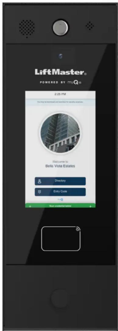
CAPXM Overview
Smart Video Intercom M (Model CAPXM) is a cloud based access control solution that includes an integrated video camera enabling advanced video features.
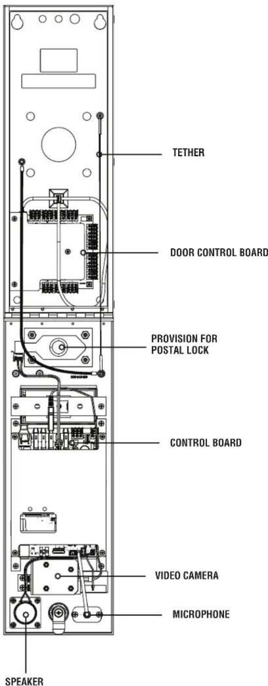
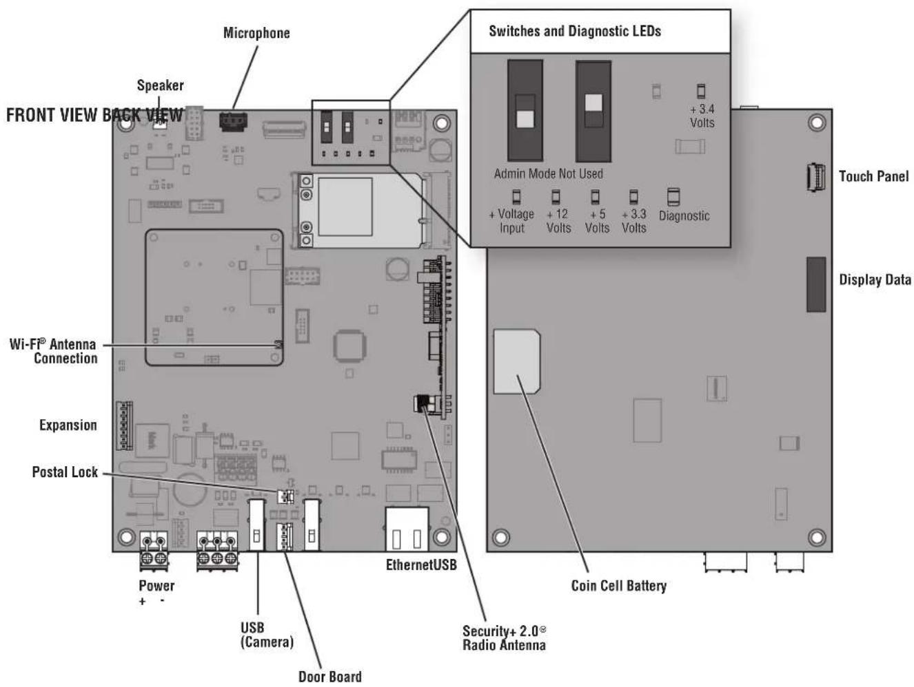
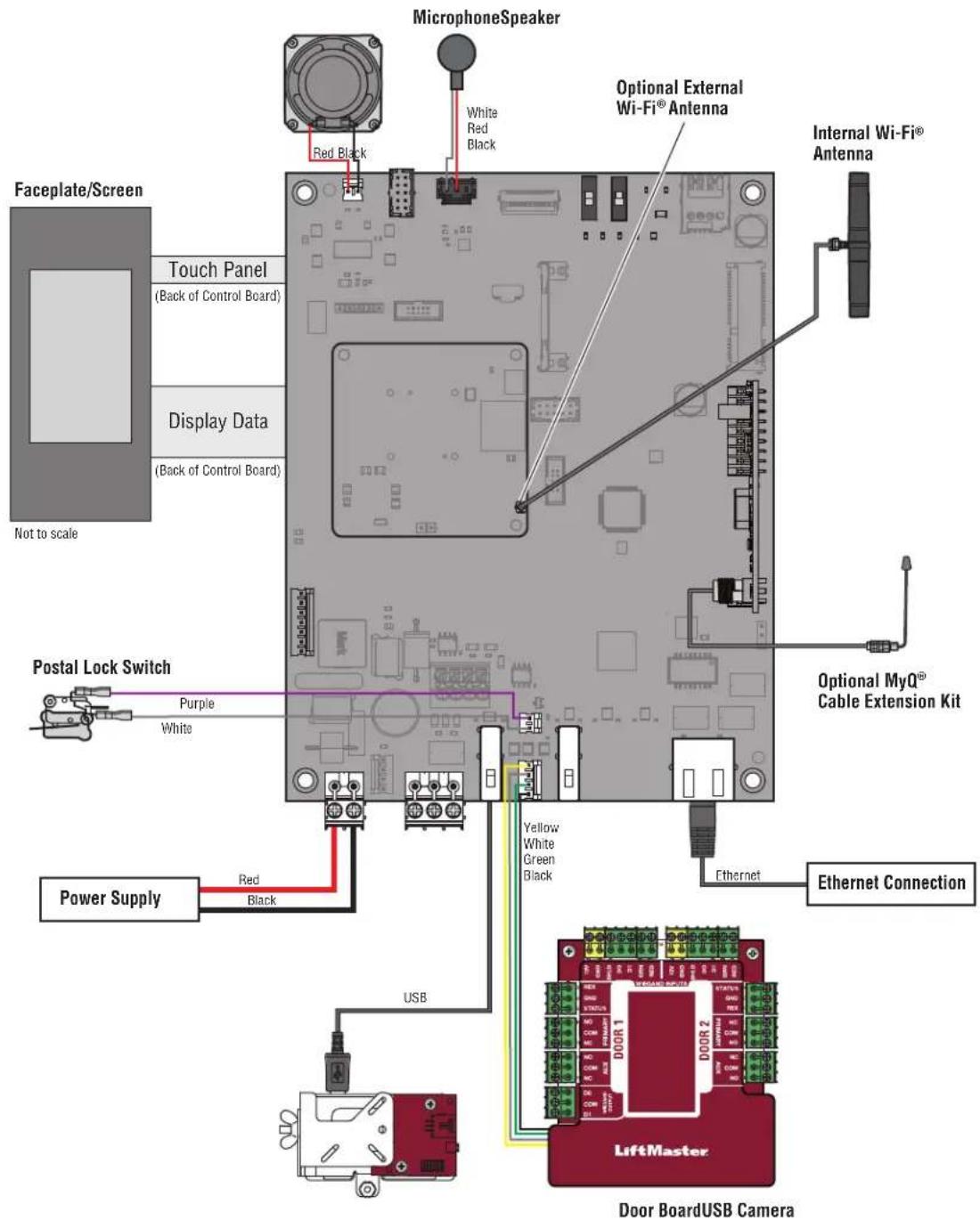
Control Board Overview
Door Board Overview
The CAPXM has a combination of access control inputs/outputs on the Door Board that work in conjunction to control up to 2 access points.
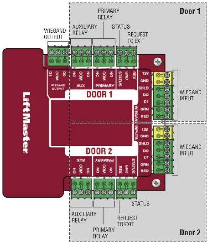
DOOR BOARD
See page 17 for wiring diagram.
| INPUT/OUTPUT USED FOR | |
| Relay Output 1 | Gated Operator, Door Strikes, Maglocks, Lights (for control-only power to be provided by external power supply), Alarm Shunt |
| Relay Output 2 | |
| Wiegand Output 1 | Standard 26-bit, 30-bit Wiegand, HID 37-bit with Facility Code, Transcore 37-bit, 32-bit MiFare |
| Wiegand Output 2 | |
| Supervised Input 1 | Closed Door Sensor (Supervised EOL or unsupervised), Closed Limit Gate Sensor (Supervised EOL or unsupervised), Open Limit Gate Sensor (Supervised EOL or unsupervised) |
| Supervised Input 2 |
NOTE: Only the 26-bit Wiegand protocol is compatible in UL installations.
Carton Inventory
PROVIDED (NOT SHOWN)
Installation Manual
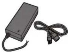
Power Supply
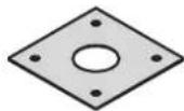
Goose-neck Gasket

S10K30MOV
(Metal Oxide Varistor)(4)
PK625 Keys (2)

1N4005 Diode Kit (4)
Tools Needed
PH2 Phillips Screwdriver
- Precision 1/8" Flat or PHO Phillips Screwdriver
1/4" Nut Driver
Drill/Driver
7/64" Drill Bit
- Hammer Drill Bits for Drill/Driver
- RJ45 Crimping Pliers
Multimeter
- Measuring tape
Conduit Bender
Conduit Cutter/Reamer
- Hack Saw
Center Punch Tool
Hammer
Additional Tools Recommended
Network LAN Cable Tester
- Wi-Fi Analyzer App (smartphone app)
Network Analyzer software
Computer with Ethernet port
- Ethernet patch cable
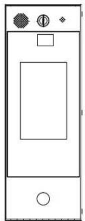
Dimensions
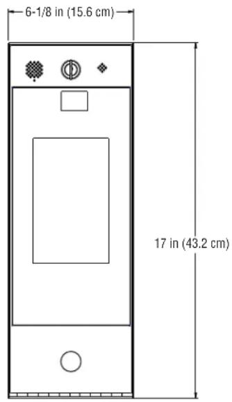
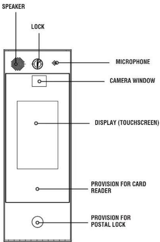
FRONT VIEW
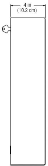
SIDE VIEW BACK VIEW
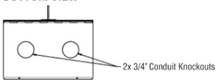
BOTTOM VIEW
Specifications
| CAPXM Capacity Resident Capacity 50,000 / Local Event History 50,000 | |
| Supply Voltage 24VDC, 60W (minimum), Class 2 Output, Level VI Efficiency, (Power Supply 120VAC, 60Hz, 2A) | |
| Operating Current 0.75A (typical) at 24VDC, 3A Max at 15VDC | |
| Surge Suppression EFT: 2 kV Power Line, ESD: 15 kV HBM / 8 kV Direct / 200V MM | |
| CAPXM Operating Temperature Range - 29°C to 54°C (-20°F to 130°F) | |
| Enclosure Carbon Steel and Aluminum | |
| Storage and Shipping Temperature Range -40°C To 65°C (-40°F to 149°F) | |
| Wiegand Inputs (2) | 26-bit, *30-bit, *32-bit Mifare, *37-bit with and without facility code, and ASCII (for keypads). 12VDC, 250mA power output (per input). |
| 2 Primary and 2 Auxiliary Relay Outputs SPDT, Rated | Load 3A at 30VDC (each) |
| Accessory Compatibility Refer to the accessory page | for compatible accessories |
| Network Compatibility 10/100 Ethernet | |
| Wi-Fi® Compatibility 802.11b/g/n @ 2.4 Ghz | |
| Wi-Fi® Security CAPXM is compatible with routers using the following security protocols: WPA3 Personal and WPA2 Personal (AES). | |
| Wi-Fi® Range Up to 250 feet (76.2 m), Open Air/Line-of-Sight to front of panel (range will vary depending on obstructions) | |
| Built-in LiftMaster Passport Receiver Security+ 2.0 | ° |
| Wireless Communication to Gate Operator | Up to 750 feet (228.6 m), Open Air/Line-of-Sight (range will vary depending on obstructions), Compatible with LiftMaster Security+ 2.0° gate operators, 2018 LiftMaster Gate Operators (firmware v4.4 and later), HD Operators (firmware v3.3 or later). NOT compatible with LiftMaster Barrier Gate Operators. |
| CAPXM Video Camera | 1080p, Viewing angle - 135 degree diagonal, Up to 1,000 30-second temporary video events stored locally |
*NOTE: Only the 26-bit Wiegand protocol is compatible in UL installations. Wi-Fi and wireless ranges were not evaluated by UL.
Wire Specifications
Use this chart to pull wires in preparation of your installation. Check the national and local building codes BEFORE installation.
| DESCRIPTION OF WIRE RUN WIRE SPECIFICATION MAXIMUM RUN DISTANCE | ||
| Power Wire, secondary DC output 2-Conductor 14 AWG | 2-Conductor 16 AWG | Up to 300 feet (91.4 m) |
| Up to 200 feet (60.9 m) | ||
| 2-Conductor 18 AWG | Up to 100 feet (30.4 m) | |
| Local Area Network (LAN) | 8-Conductor, 24 AWG Twisted pair 328 feet* (100 m) | |
| CAT 5e or better Network Cable. | ||
| Grounding the Chassis (use grounding lug in CAPXM) | 12 AWG Copper 12 feet (3.7 m) | |
| Door Strike 2-Conductor 18-22 AWG Shielded 100 - 250 feet (30.5 - 76.2 m) | ||
| Magnetic Lock 2-Conductor 18-22 AWG 50 - 125 feet (15.2 - 38.1 m) | ||
| Dry Contact Closure (Most Gate Operators) 2-Conductor | 18-24 AWG Shielded 500 - 2500 feet (152.4 - 762 m) | |
| Exit Request (REX) 2-Conductor 18-24 AWG 500 feet (152.4 m) | ||
| Supervised Input 2-Conductor 18-24 AWG 500 feet (152.4 m) | ||
| Wiegand/Proximity Readers 7-Conductor 18-22 AWG Shielded 500 feet (152.4 m) | ||
NOTE: Main power supply and control wiring MUST be run in separate conduits. Conduits must be UL approved for low and high voltage. Refer to the NEC for additional wiring requirements.
Category 5e cabling is the minimum performance category recommended.
Wiring shall be in accordance with the National Electrical Code (ANSI/NFPA 70), local codes and authorities having jurisdiction. Always provide power from a dedicated source. Plug provided transformer into an outlet wired to its own 10 Amp minimum circuit breaker. This will prevent two problems:
- Other equipment cannot introduce spikes, noise, surges or dips into the power circuit that will affect the system.
- The system's operation will not be affected if any other equipment develops a short circuit across the power line.
* CAT 5/6 NETWORK CABLE NOTES:
- For outdoor distances exceeding 140 feet (42.7 m), a UL497 compliant primary surge protector MUST be installed at the CAPXM.
Distances exceeding 328 feet (100 m) may be accommodated with additional hardware (available through third-party sources).
Internet Requirements
When selecting a router, use the information below to ensure compatibility.
MODEL: CAPXM - Smart Video Intercom M
CAPXM can be connected to a router via a wired connection or Wi-Fi. LiftMaster recommends a minimum upload/download speed of 5Mbps for each CAPXM supporting video camera feeds.
NOTE: This upload speed should be met when considering usage of other devices on the network like cameras and computers.
CAPXM IS COMPATIBLE WITH ROUTERS USING THE FOLLOWING Wi-Fi COMMUNICATION PROTOCOLS:
802.11b
802.11g
- 802.11n @ 2.4 GHz
CAPXM WI-FI SECURITY COMPATIBILITY
WPA3 Personal
WPA2 Personal (AES)
ADDITIONAL COMPATIBILITY CONSIDERATIONS:
DO NOT use Wi-Fi extender devices. These may introduce latency in the connection leading to choppy or loss of reliable video transmission.
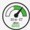
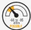
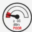
- If using a Wi-Fi signal strength tool or app, a continuous Wi-Fi signal strength connection of at least -65 DBM (numbers closer to zero are stronger strength) at the CAPXM must be guaranteed to ensure an acceptable connection to the local network.
- Hidden network SSIDs are not supported. The network must be selectable from the CAPXM display.
- Wi-Fi networks requiring secondary authentication are not supported (E.g. Hotels and airport Wi-Fi).
- When checking signal strength in CAPXM admin mode, we recommend at least two bars, as shown on the CAPXM screen.
- If two bars are not available, relocate the router, the antenna or use accessory WFAEXT (Wi-Fi Antenna Extension Kit - 15') to move the
CAPXM antenna higher up or to a location resulting in two or more bars.
The following services are required for CAPXM to fully function
Setup a myQ® Business™ Account

NOTE: If you have an existing myQ account, your myQ Business account will have the same password. Go to: myQBusiness.com and login.
- If you do not have a myQ Business™ account, call LiftMaster Customer Care at 800.323.2276 to activate a myQ Business™ account.
Be prepared by reviewing the information required on the Installation Readiness Survey:
- You will get a welcome email from LiftMaster. Accept the invitation and register or login to your account.
- Setup the facility, select a subscription plan, add residents, and credentials (refer to the available Help in myQ BusinessTM).
- Continue with the installation of the CAPXM in this manual.
For Support, call 800.528.2806 or visit https://supportpartner.liftmaster.com/s/community-access-support

NOTE: A SIP account is required for calling function. LiftMaster® only supports Phone.com for video calling features and cannot guarantee or support 3rd party SIP provider's compatibility for voice only calling.

Remove Knockouts
- Prepare the work surface by laying down a cloth or other protective material.
- Lay the CAPXM face down on the protective material.
- Identify which knockouts need to be removed based on your application.
- Use a center punch tool to remove the knockouts from the outside of the box inward using an appropriately sized punch and hammer. NOTE: Be careful when removing the knockouts to avoid damaging the CAPXM components.

CAUTION
To prevent damage to the CAPXM from moisture or water:
- DO NOT install during rain. Internal components MUST be kept from of water and moisture.
BEFORE opening the front cover of the CAPXM, remove ANY accumulated water from the top of the CAPXM.
To prevent damage to ANY internal components:
- DO NOT attempt to remove the knockouts with a hammer. Banging on the knockouts may result in shock to the circuit boards, which could cause permanent damage.
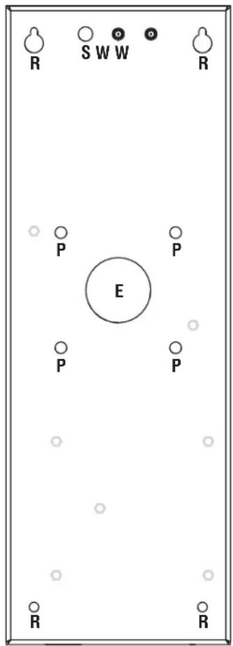

E = Electrical Wiring
P = Pedestal Mount
R = Recess/Surface Mount
S = Security + 2.0
Radio Antenna
W = Wi-Fi Antenna

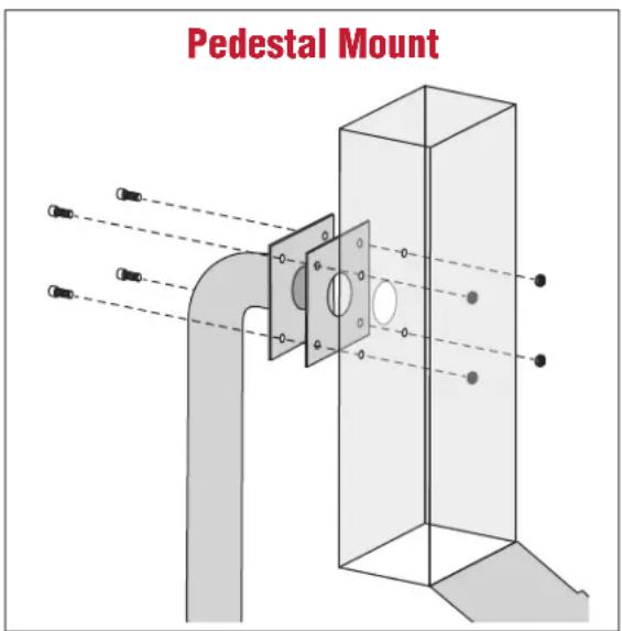
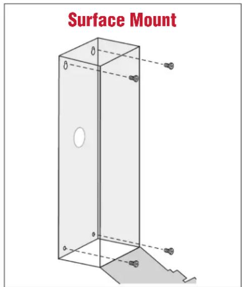
Mount CAPXM
- Attach the goose-neck gasket (provided) if mounting to a goose-neck.
- Mount the CAPXM securely to a flat surface or pedestal with appropriate (1/4 in.) hardware taking care to route wiring through appropriate knockouts. Stainless steel hardware is recommended to mount the CAPXM. Use of zinc plated or galvanized hardware is at risk for galvanic corrosion.
DO
Make sure the CAPXM is properly sealed to prevent damage to the CAPXM from moisture.
NOTES:
- Ensure the cover can fully open to allow access after the installation is complete. Allow 1/8 in. (3.175 mm) of space between the bottom of CAPXM and the wall, if flush-mounting CAPXM without the trim kit.
-ADA Compliance: When mounting the CAPXM at a pedestrian entrance, to meet ADA compliance, mount the top of the CAPXM screen no higher than 54 inches from the ground.

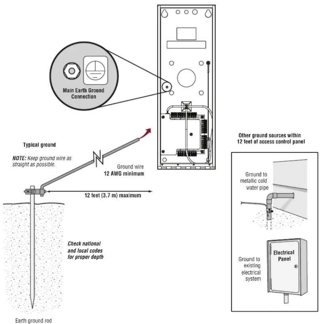
Install the Ground
IMPORTANT: An earth ground rod is strongly recommended and should be no further than 12 feet (3.7m) from the CAPXM and use a minimum of 12 gauge wire in most cases. The type and length of earth ground rods vary by region. Contact the AHJ (Authority Having Jurisdiction) in the municipality where you plan to install the CAPXM for correct grounding materials and installation procedures. A proper ground is critical to minimizing risk for the CAPXM from damaging electrical transients.
- Connect the ground wire (12 AWG or larger) to the CAPXM main earth ground connection.
- Run the wire from the CAPXM to suitable earth ground.
NOTE: Shield connections on boards should not be connected to main earth ground connection.

CAUTION
To AVOID damaging gas, power or other underground utility lines, contact underground utility locating companies BEFORE digging.

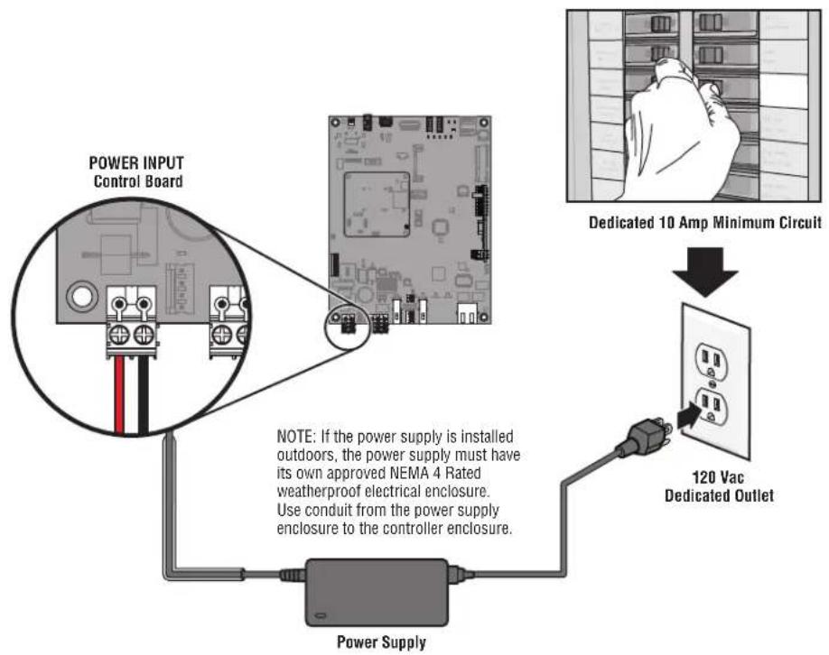
Connect Power
The outlet for the CAPXM MUST be an external dedicated 120 Vac outlet. Refer to the table below for maximum wire run distances. This outlet should be wired back to its own 10 Amp minimum circuit breaker.
| WIRE SPECIFICATION MAXIMUM RUN DISTANCE | |
| 14 AWG Up to 300 feet | (91.4 m) |
| 16 AWG Up to 200 feet | (60.9 m) |
| 18 AWG Up to 100 feet | (30.4 m) |
- Connect 14-18 AWG wire to the stripped secondary DC output wires on the power supply. Black is negative and red is positive.
- Remove the PWR INPUT terminal block from the Control Board.
- Connect the power supply wires to the PWR INPUT terminal block (red to +24V and black to GND). Reattach the terminal block to the Control Board.
- Plug the power supply into a 120 Vac outlet after all connections have been made.
NOTE: The green LED on the door board will blink and the green LEDs on the Control Board will light solid when powered up. The CAPXM will display the LiftMaster logo while booting up. When boot up is complete, the user interface will appear.
CAUTION
DO NOT use ANY power supply other than those supplied with your CAPXM.
DO NOT power electronic strikes and latches with the same power supply used to power the access control panel; doing so will cause DAMAGE to the CAPXM. Use ONLY a UL listed burglar alarm or access control system to power electronic strikes and latches.
DO NOT connect the power supply to a switched outlet or otherwise controlled AC outlet.
DO NOT connect the power supply to the 120 Vac outlet until ALL wiring is completed.
- Install the transient noise suppression device (MOV) supplied with the CAPXM for AC powered devices and Diode for DC powered devices.
- DISCONNECT the power supply from the 120 Vac outlet prior to removing or attaching the terminal block to the Control Board.
- Close the CAPXM door.
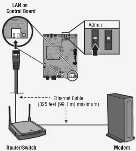
Connect Internet
The CAPXM can connect to the Internet with a wired connection or with Wi-Fi® (wireless). See page 10 for Internet requirements. Make sure you are in the Admin Mode before you connect to the Internet. If you are not in Admin Mode, flip switch #1 to the ON position on the Control Board, press the Network tab on the CAPXM display, and press the "Change Network Settings" button. Follow the instructions according to your application.
OPTION 1 Wired Connection
The Local Area Network (LAN) port is a 10/100 Ethernet interface with an RJ45 jack for connecting the CAPXM to a hub, switch, or router in order for it to gain connectivity to the Internet. Use a straight, (i.e., non-crossover) Cat5e, or Cat6 cable to connect to a local hub, switch or router. This type of cable is referred to as an Ethernet cable in this manual.
- Connect an Ethernet cable from the hub, switch, or router to the LAN port on the Control Board. When connected properly, the green and amber LED on the Ethernet port of the control board will light/flicker (the control board is located on the back of the CAPXM display). If the green LED is not lit, check the connections on the CAPXM and the Ethernet hub.
- On the display, select Wired Network if dynamic configuration (DHCP) is desired or select Manual Setup for a static IP address.
OPTION 2 Connect through Wi-Fi® (Wireless)
- On the display select Wi-Fi Network.
- Select the network the CAPXM will use.
- Enter the password for the network.
- Select Login.
Additional compatibility considerations:
- When checking signal strength in CAPXM admin mode, we recommend at least two bars.
- If two bars are not available, relocate the router, the antenna or use accessory WFAEXT (Wi-Fi Antenna Extension Kit - 15') to move the CAPXM antenna higher up or to a location resulting in two or more bars.
- If using a Wi-Fi® signal strength tool or app, a continuous Wi-Fi® signal strength connection of at least -65 dBm (numbers closer to zero are stronger strength) at the CAPXM must be guaranteed to ensure an acceptable connection to the local network.
- Hidden network SSIDs are not supported. The network must be selectable from the CAPXM display.
Wi-Fi® networks requiring secondary authentication are not supported (E.g. Hotels and airport Wi-Fi®).
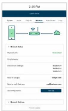
2 Validate Setup
On the display, select each tab in Admin Mode to validate setup (network, inputs, outputs, etc.). Once you have validated the setup, exit Admin Mode.
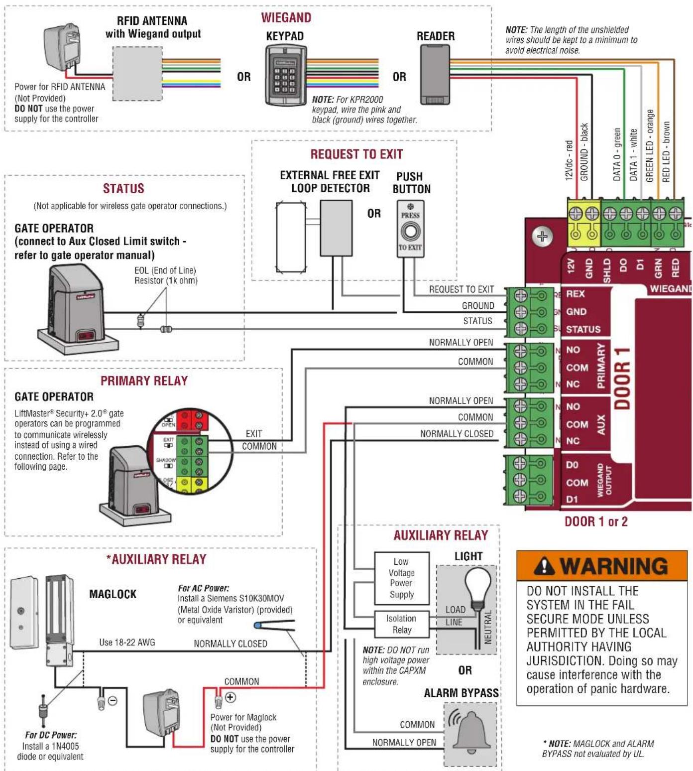
Gate Access (Wired)
Disconnect power BEFORE making electrical connections. Below is an example of a wiring setup for gate access. Gate access can be wired to Door 1 or 2 on the Door Board. LiftMaster® Security+ 2.0^® gate operators can also be programmed to communicate wirelessly instead of using a wired connection (refer to the following page).
Gate Access (Wireless)
The CAPXM can communicate wirelessly to LiftMaster® UL325 gate operators to send open commands, monitor gate position, and send email notifications if an error occurs in the operator (email notifications are configured in myQ® Business™). Up to 4 gate operators can be paired with the CAPXM - one for each primary and auxiliary relay. If using dual gates, program the CAPXM to the primary operator.
NOTE: Use of this feature requires the optional Passport antenna kit.
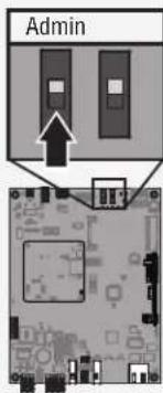
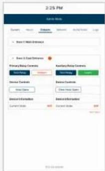
1 Enter Admin Mode
Flip switch #1 to the ON position to enter Admin Mode.
NOTE: For new installations press the login button without entering information in the Admin username and Admin Password fields.
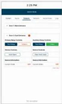
2 Select Outputs and Relay
Select the Outputs tab. Then select the desired relay on the left-hand side (1 through 4).
3 Press LEARN button on gate operator
Press and release the LEARN button on the primary operator. The green XMITTER LED will light. NOTE: The operator will time out of programming mode after 180 seconds.
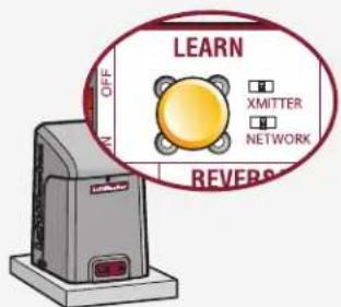
4 Press LEARN button on gate operator again
Press and release the LEARN button again on the primary operator. The yellow NETWORK LED will light.
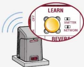
5 Select LEARN on display
Select the LEARN button on the display and the Learn button will go from blue to red. The gate operator and the CAPXM will beep once and the NETWORK LED on the gate operator will turn off indicating programming is successful.
NOTE: 4 beeps/blinks indicate you are not programming to the primary operator. Reattempt programming from the other operator.
6 Validate
Validate functionality by selecting Test Relay on the CAPXM display.
Visit myQBusiness.com for more information on how to set up doors for wireless linking.
Door Access
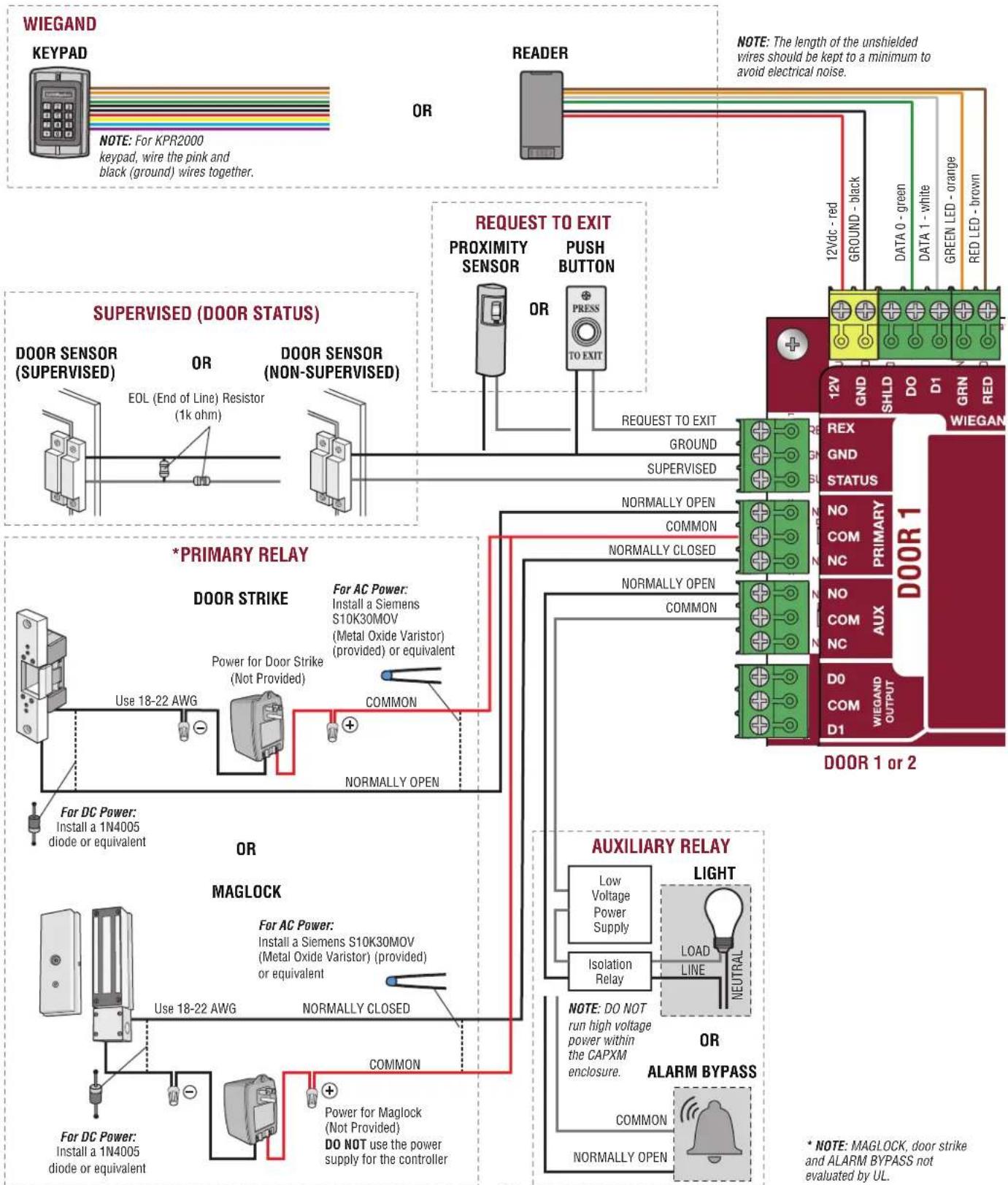
Disconnect power BEFORE making electrical connections. Below is an example of a wiring setup for door access. Door access can be wired to Door 1 or 2 on the Door Board.
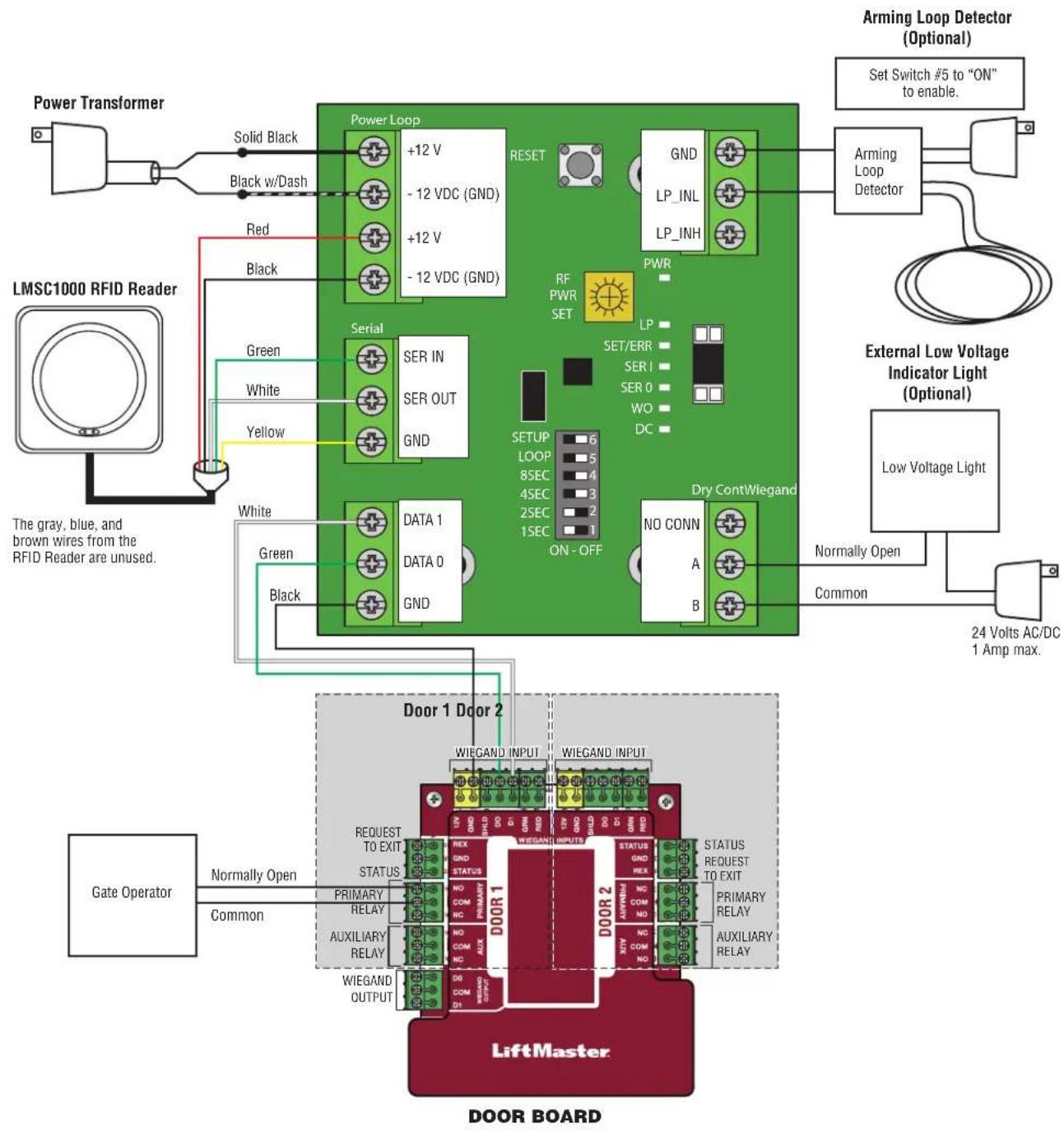
LiftMaster LMSC1000 RFID Reader Wiring Diagram
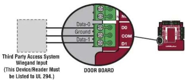
Wiegand Output
Disconnect power BEFORE making electrical connections. The CAPXM offers a Wiegand output capable of 26-bit transmission of the following data:
Success Call with access granted by the resident. The CAPXM will provide a myQ Business™ specified facility code followed by the Directory Code of the resident that granted access.
And/Or
- Successful access through Entry Code. The CAPXM will provide a myQ Business™ specified facility code followed by the successful Entry Code.
And/Or
- Successful access with a Wiegand credential. The CAPXM will pass along the successful credential Facility Code and ID.
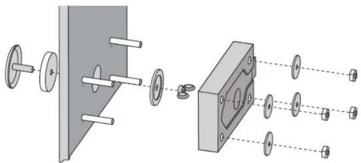
Postal Lock
- Remove the wing nut and plug. Discard the wing nut and plug.
- Remove 4 mounting nuts from studs.
- Install postal lock using 4 nuts.
- Cut the factory installed wire tie from the postal lock switch.
- The postal lock switch is wired from the factory.
Not responsible for conflicts between the information listed in the wiring diagram and the requirements of your local building codes. The information is for suggested use ONLY. Check your local codes BEFORE installation.
Repair Parts
| ITEM PART NUMBER | |
| Cam and Lock Kit K41-0215-000 | |
| Front Panel with Display Kit, CAPXM K41-0216-000 | |
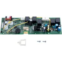
| Control Board, CAPXM K41-0217-000 | |
| Microphone Kit, CAPXM K41-0223-000 | |
| Postal Lock Switch, CAPXM K41-0219-000 | |
| Rear Housing Assembly, CAPXM K41-0220-000 | |
| Wiring Kit, CAPXM K41-0221-000 | |
| Speaker Kit, CAPXM K41-0222-000 | |
| Power Supply Kit K41-0227-000 | |
| Door Board and Covers K001D8478 | |
| USB Camera Kit CAPXLCAM |
Accessories
| ITEM PART NUMBER | |
| Reader Multi-class SE RP10 Mini Mullan LMMC-MINI | |
| Wi-Fi® Antenna Kit K76-38957 | |
| Radio Antenna Kit K76-38958 | |
| Radio Antenna Extension (15 foot) | 86LM |
| Wi-Fi® Antenna Extension (15 foot) | WFAEXT |
| Wi-Fi®/Bluetooth® External Antenna | WFBTEXT |
| ESARM Antenna | XMANTKIT |
| Internal Proximity Reader | XMRDRKIT |
| Wiegand Keypad/Proximity Reader | KPR2000* |
| Connected Access Portal 2 Door | CAP2D |
| Cellular 4G/LTE Modem with Wi-Fi® | CAPCELL |
| All LiftMaster® myQ®/UL325 compatible gate operators | |
| Passport 3-Button Visor Remote Control MAX | PPV3M |
| Passport 3-Button Mini Remote Control MAX | PPK3M |
| Passport 3-Button Mini Proximity Remote Control MAX | PPK3PHM |
| Passport Lite 1-Button Visor Remote | PPLV1-X** |
| Passport Lite 1-Button Key Chain Remote | PPLK1-X** |
| Passport Lite 1-Button Mini Proximity Remote | PPLK1PH-X** |
| RFID Long Range Reader | LMSC1000 |
| RFID Universal Tag (windshield/headlamp) | LMUNTG |
| RFID Vehicle Hang Tag | LMHNTG |
* KPR2000 is not UL listed to UL 294. It cannot be used as primary means of granting or denying access but only for supplemental use. ** Available in 10 and 100 packs, replace X with 10 or 100
NOTE: A current list of compatible readers and key pads is maintained at LiftMaster.com. If you have a specific model of reader or keypad that is not listed on the LiftMaster website, please contact LiftMaster Technical Support to determine compatibility.
Configuration Sheet
Record device information and configuration settings below.
| CAPXM Name: NOTE: Any user of the system is subject to the terms outlined in the product EULA. |
| Notes: |
DEVICE CONFIGURATION:
| DOOR 1 | DOOR/GATE NAME: | |||
| INPUTS | WIEGAND REX STATUS | |||
| EOL (Y/N) | ||||
| OUTPUTS | PRIMARY RELAY AUXILIARY RELAY | |||
| N.O. N.C. N.O. N.C. | ||||
| Notes: | ||||
| DOOR 2 | DOOR/GATE NAME: | |||
| INPUTS | WIEGAND REX STATUS | |||
| EOL (Y/N) | ||||
| OUTPUTS | PRIMARY RELAY AUXILIARY RELAY | |||
| N.O. N.C. N.O. N.C. | ||||
| Notes: | ||||
Legal Disclaimers
Canada-Underwriters Laboratories Compliance
The CAPXM shall be installed in accordance with Part 1 of the Canadian Electrical Code.
Documentation Disclaimer and Restrictions
Information in this document is subject to change without notice and does not represent a commitment on the part of LiftMaster. For the most up-to-date information, visit LiftMaster.com.
This document and the data herein shall not be duplicated, used or disclosed to others for procurement or manufacturing, except as authorized with the written permission of LiftMaster. The information contained within this document or within the product itself is considered the exclusive property of LiftMaster. All information in this document or within the hardware and software product themselves is protected by the copyright and/or other intellectual property laws of the United States.
UL 294 Access Control Unit Endurance: Level 3, Line security: Level 1, Destructive Attack: Level 1, Power Standby: Level 1
NOTICE: This device complies with part 15 of the FCC rules and Innovation, Science and Economic Development Canada license-exempt RSSs. Operation is subject to the following two conditions: (1) this device may not cause harmful interference, and (2) this device must accept any interference received, including interference that may cause undesired operation. Any changes or modifications not expressly approved by the party responsible for compliance could void the user's authority to operate the equipment.
This device must be installed to ensure a minimum 20 cm (8 in.) distance is maintained between users/bystanders and device.
This device has been tested and found to comply with the limits for a Class B digital device, pursuant to part 15 of the FCC rules and Industry Canada ICES standard. These limits are designed to provide reasonable protection against harmful interference in a residential installation. This equipment generates, uses and can radiate radio frequency energy and, if not installed and used in accordance with the instructions, may cause harmful interference to radio communications.
However, there is no guarantee that interference will not occur in a particular installation. If this equipment does cause harmful interference to radio or television reception, which can be determined by turning the equipment off and on, the user is encouraged to try to correct the interference by one or more of the following measures:
- Reorient or relocate the receiving antenna.
- Increase the separation between the equipment and receiver.
- Connect the equipment into an outlet on a circuit different from that to which the receiver is connected.
- Consult the dealer or an experienced radio/TV technician for help.
NOTICE: When mounting the CAPXM at a pedestrian entrance, to meet ADA compliance, mount the top of the CAPXM screen no higher than 54 inches from the ground.
NOTE: When installing CAPXM, please refer to the local jurisdiction for any specific requirements such as physical signage that may be required.
Warranty
LiftMaster ("Seller") warrants to the first purchaser of this product, for the structure in which this product is originally installed, that it is free from defect in materials and/or workmanship for a period of two years from the date of purchase.
The proper operation of this product is dependent on your compliance with the instructions regarding installation, operation, maintenance and testing. Failure to comply strictly with those instructions will void this limited warranty in its entirety.
If, during the limited warranty period, this product appears to contain a defect covered by this limited warranty, call 1-800-528-2806 before dismantling this product. Then send this product, pre-paid and insured, to our service center for warranty replacement. Products returned to Seller for warranty replacement, which upon receipt by Seller are confirmed to be defective and covered by this limited warranty, will be replaced (at Seller's sole option) at no cost to you and returned pre-paid. Defective parts will be replaced with new or factory-rebuilt parts at Seller's sole option.
THIS LIMITED WARRANTY IS IN LIEU OF ANY OTHER WARRANTYES, EXPRESS OR IMPLIED WARRANTY OF MERCHANTABILITY OR FITNESS FOR A PARTICULAR PURPOSE OR OTHERWISE, AND OF ANY OTHER OBLIGATIONS OR LIABILITY ON SELLER'S PART. THIS LIMITED WARRANTY DOES NOT COVER NON-DEFECT DAMAGE, DAMAGE CAUSED BY IMPROPER INSTALLATION, OPERATION OR CARE (INCLUDING, BUT NOT LIMITED TO ABUSE, MISUSE, FAILURE TO PROVIDE REASONABLE AND NECESSARY MAINTENANCE, UNAUTHORIZED REPAIRS OR ANY ALTERATIONS TO THIS PRODUCT), LABOR CHARGES FOR REINSTALLING A REPAIRED OR REPLACED UNIT, PROBLEMS RELATED TO INTERFERENCE, OR REPLACEMENT OF BATTERIES.
UNDER NO CIRCUMSTANCES SHALL SELLER BE LIABLE FOR CONSEQUENTIAL, INCIDENTAL OR SPECIAL DAMAGES ARISING IN CONNECTION WITH USE, OR INABILITY TO USE, THIS PRODUCT. IN NO EVENT SHALL SELLER'S LIABILITY FOR BREACH OF WARRANTY, BREACH OF CONTRACT, NEGLIGENCE OR STRICT LIABILITY EXCEED THE COST OF THE PRODUCT COVERED HEREBY. NO PERSON IS AUTHORIZED TO ASSUME FOR US ANY OTHER LIABILITY IN CONNECTION WITH THE SALE OF THIS PRODUCT.
Some states do not allow the exclusion or limitation of consequential, incidental or special damages, so the above limitation or exclusion may not apply to you. This limited warranty gives you specific legal rights, and you may also have other rights which vary from state to state.
myQ® Business™
Smart Video Intercom M
MANUEL D'INSTALLATION
Modèle CAPXM
Sécurité
MODELE: CAPXM - Smart Video Intercom M
WPA3 personnel
- WPA2 personnel (AES)
CONSIDERATIONS SUPPLEMENTaires DE COMPATIBILITE:
SE INCLUYE (NO SE MUESTRA)
WPA3 personal
WPA2 Personal (AES)
Wi-Fi® is a registered trademark of Wi-Fi Alliance®.