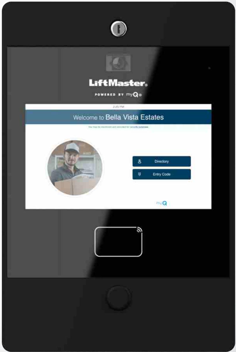
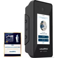
CAPXLV2 - Video Intercom LIFT-MASTER - Free user manual and instructions
Find the device manual for free CAPXLV2 LIFT-MASTER in PDF.
| Product Type | Video Intercom |
| Brand | LIFT-MASTER |
| Model | CAPXLV2 |
| Power Supply | 24 VDC 72 W (3 A max.) or PoE 36-55 VDC 60 W max (802.3bt Type 3) |
| Power Consumption | 72 W (via power adapter) or 60 W (via PoE) |
| Main Functions | Access control for up to 8 points, 1080p camera, video intercom, WiFi, Bluetooth, OSDP/Wiegand reader, relay outputs |
| Capacity | 50,000 residents / 50,000 local events |
| Network Connectivity | Ethernet 10/100, WiFi 802.11 a/b/g/n/ac (2.4/5 GHz), Bluetooth 5.0 |
| Video Camera | 1080p, 135° diagonal angle, local recording up to 1000 clips of 30 s |
| Inputs/Outputs | 8 SPDT relays, 8 supervised inputs, 4 Wiegand inputs, 1 OSDP bus (up to 8 readers) |
| Operating Temperature | -20 °C to 50 °C |
| Storage Temperature | -40 °C to 85 °C |
| Housing | Aluminum front, carbon steel back |
| Compliance Standards | UL294 |
| Power Adapter Input | 120 VAC, 1.5 A, 60 Hz |
| WiFi Range | Up to 152.4 m (line of sight) |
| Radio Range (Security+ 2.0) | Up to 228.6 m (line of sight) |
| Maintenance and Cleaning | Clean with a soft, dry cloth. Do not use abrasive products. Keep the door seal in good condition. |
| Safety | Disconnect before servicing. Grounding mandatory. Use separate conduit. Follow fire codes. |
| Spare Parts and Accessories | Power supply, antennas, gasket, keys, diode kit, resistors. Accessories: WiFi antenna WFBTEXT, extension kit WFAEXT, etc. |
| Repairability | Spare parts available from the manufacturer. Requires a qualified technician for replacement. |
Frequently Asked Questions - CAPXLV2 LIFT-MASTER
User questions about CAPXLV2 LIFT-MASTER
0 question about this device. Answer the ones you know or ask your own.
Ask a new question about this device
Download the instructions for your Video Intercom in PDF format for free! Find your manual CAPXLV2 - LIFT-MASTER and take your electronic device back in hand. On this page are published all the documents necessary for the use of your device. CAPXLV2 by LIFT-MASTER.
USER MANUAL CAPXLV2 LIFT-MASTER
Safety Symbol and Signal Word Review
When you see these Safety Symbols and Signal Words on the following pages, they will alert you to the possibility of serious injury or death if you do not comply with the warnings that accompany them. The hazard may come from something mechanical or from electric shock. Read the warnings carefully.
When you see this Signal Word on the following pages, it will alert you to the possibility of damage to your property or product if you do not comply with the cautionary statements that accompany it. Read them carefully.

WARNING
MECHANICAL

WARNING
ELECTRICAL

CAUTION

WARNING
To reduce the risk of SEVERE INJURY or DEATH:
- Disconnect power at the fuse box BEFORE proceeding.
- To AVOID damaging gas, power or other underground utility lines, contact underground utility locating companies BEFORE digging.
- ALL electrical connections MUST be made by a qualified individual.
- ALL power and control wiring MUST be run in separate conduit.
To protect against fire and electrocution:
- Disconnect power BEFORE installing or servicing CAPXLV2.
- NEVER connect a keypad/reader or lock to doors without first consulting the applicable fire code.
- You MUST consult with, and get approval from, local fire officials BEFORE installing locks or devices on ANY doors that may be fire exits.
- Use of egress push buttons may not be legal. Single action exits may be required.
- ALWAYS obtain proper permits and approvals in writing BEFORE installing equipment.
- ALWAYS ensure that the CAPXLV2 front lid is locked properly using the provided key after any servicing or maintenance of the product is complete and before operating the product.
- NEVER leave any exposed wiring inside the cabinet.

WARNING: This product can expose you to chemicals including lead, which are known to the State of California to cause cancer or birth defects or other reproductive harm. For more information go to www.P65Warnings.ca.gov.
INTRODUCTION
i
CAPXLV2 Overview 4
Main Board Overview 5
Door of Control Board Overview 6
Carton Inventory 7
Tools Needed 7
Dimensions 8
System Specifications 8
Wire Specifications 9
1 PRE-INSTALL
Setup a myQ® Community Account 10
Sign up for myQ® Community Services 10

myQ
2 INSTALL
Remove Knockouts 11
Mount the CAPXLV2. 12
Install Antennas. 13
Ground the Unit. 14
Connect Power 15
3 NETWORK
Connect Internet 16
Validate Setup 16
4 ACCESS CONTROL
Gate Access (Wired) 17
Gate Access (Wireless) 18
Door Access 19
OSDP Card Reader 20
Wiegand Card Reader 21
Wiegand Output 22
Postal Lock 23
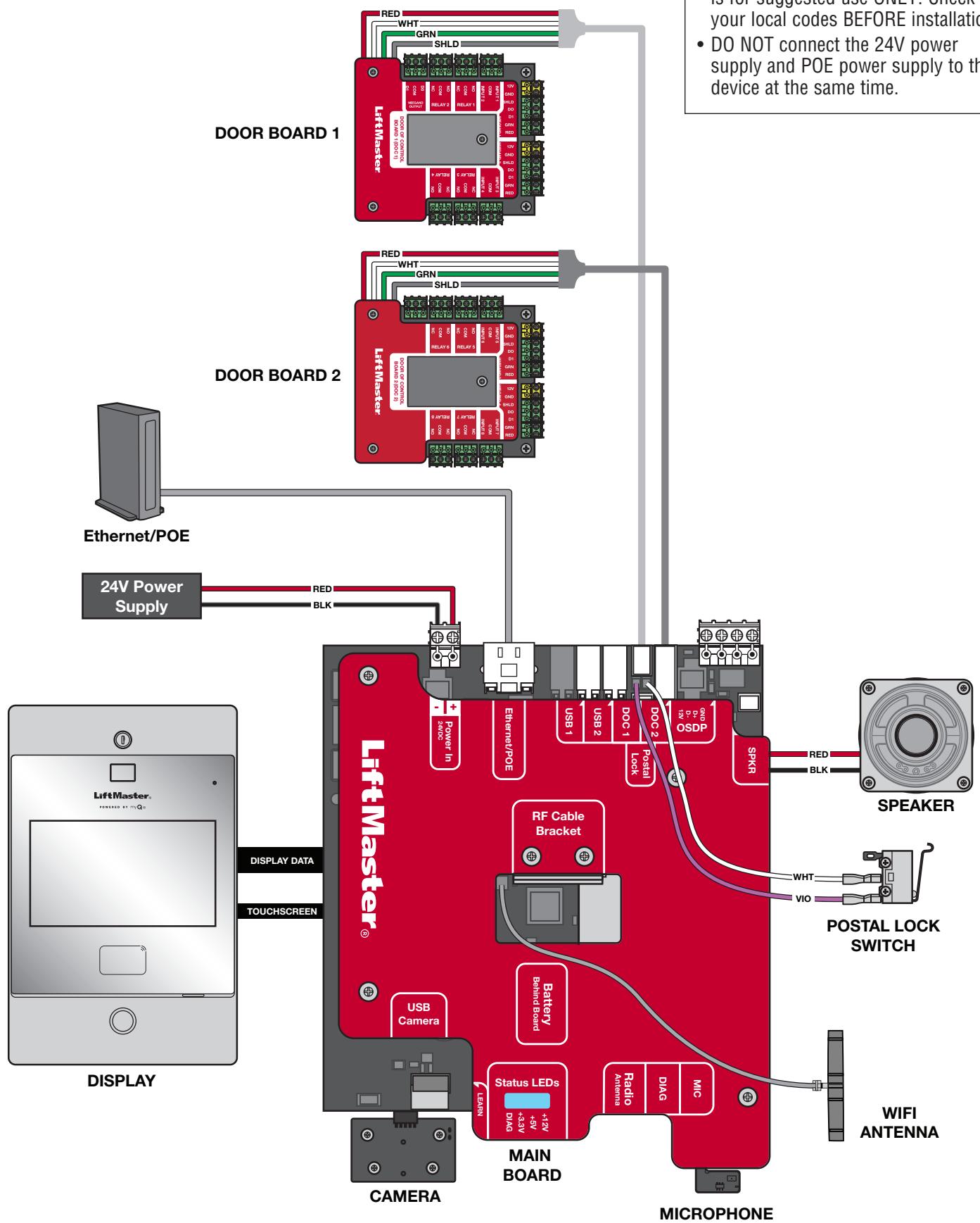
Wiring Diagram 24
Repair Parts 25
Accessories 25
Configuration Sheet 26
Legal Disclaimers 27
Warranty 28
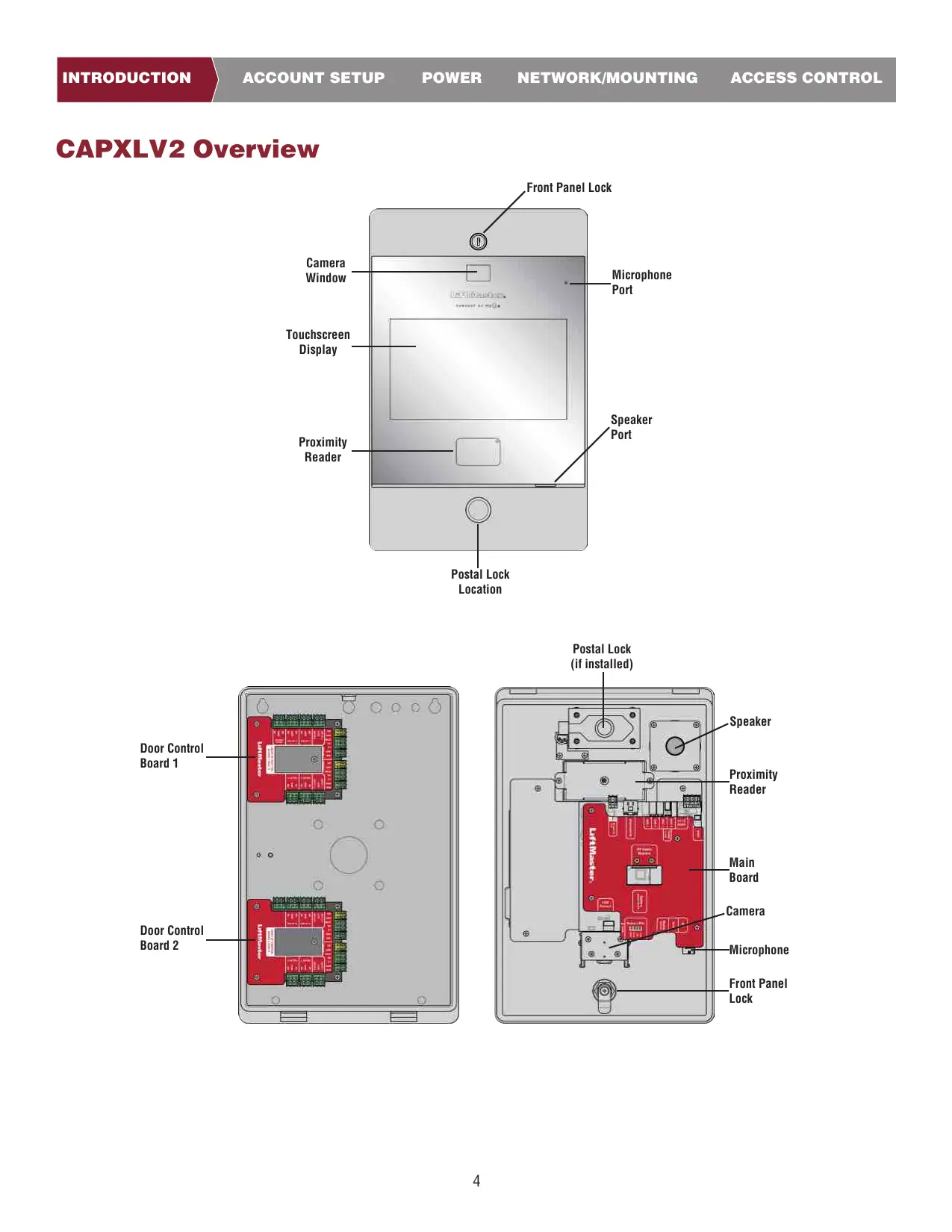
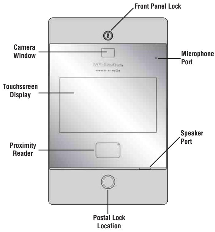
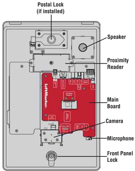
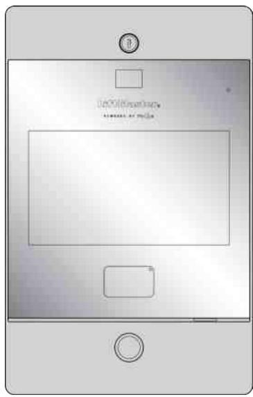
CAPXLV2 Overview
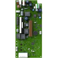
Main Board Overview
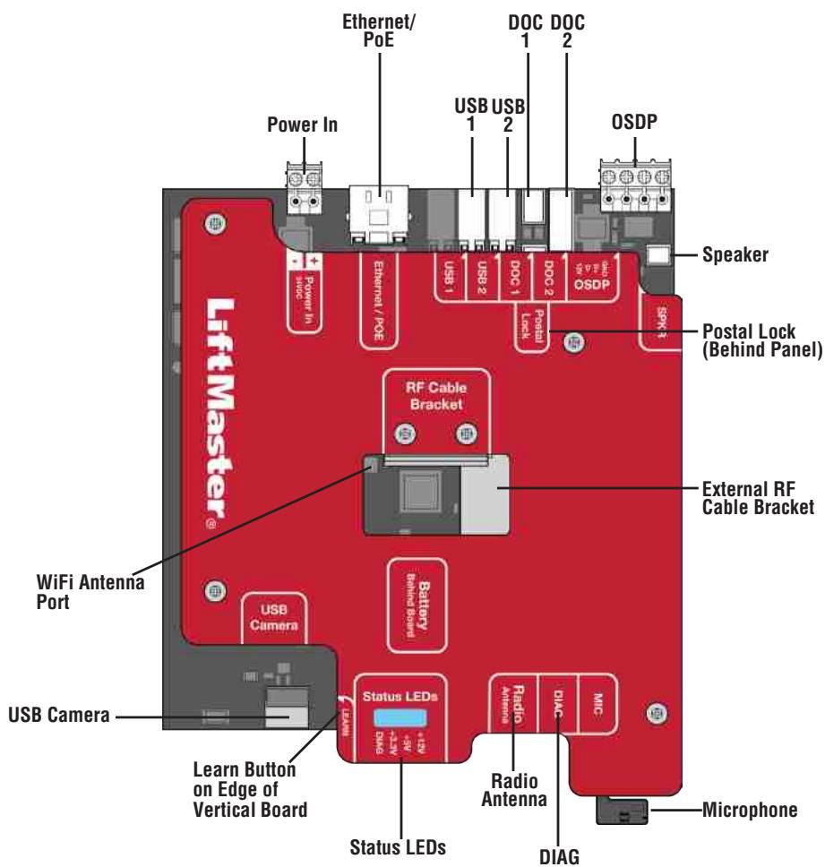
| INPUT/OUTPUT | USED FOR |
| Power In | Connect to external 24v power supply |
| Ethernet/PoE | Connect Ethernet Switch or Router for 10/100BaseT or PoE Injector for PoE power via RJ45 |
| USB1 | Reserved for future use |
| USB2 | Reserved for future use |
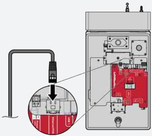
| DOC 1 | Connect to Door of Control Board 1 |
| DOC 2 | Connect to Door of Control Board 2 |
| OSDP | Connect RS-485 bus that can connect up to 8 OSDP readers in daisy chain within 1000 ft and provide 12v power to the connected OSDP readers. |
| Postal Lock | Connect to Postal Lock |
| SPKR | Connect to the built-in Speaker |
| WiFi Antenna | Connect to external WiFi antenna |
| USB Camera | Connect to the built-in Camera |
| Status LED | Display power diagnostics status: DIAG, +3.3v, +5v, +12v. |
| Radio Antenna | Connect to external radio antenna for Security + 2.0 |
| DIAG | For internal use only |
| MIC | Connect to the built-in Microphone |
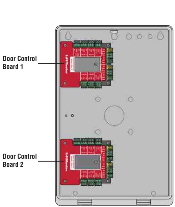
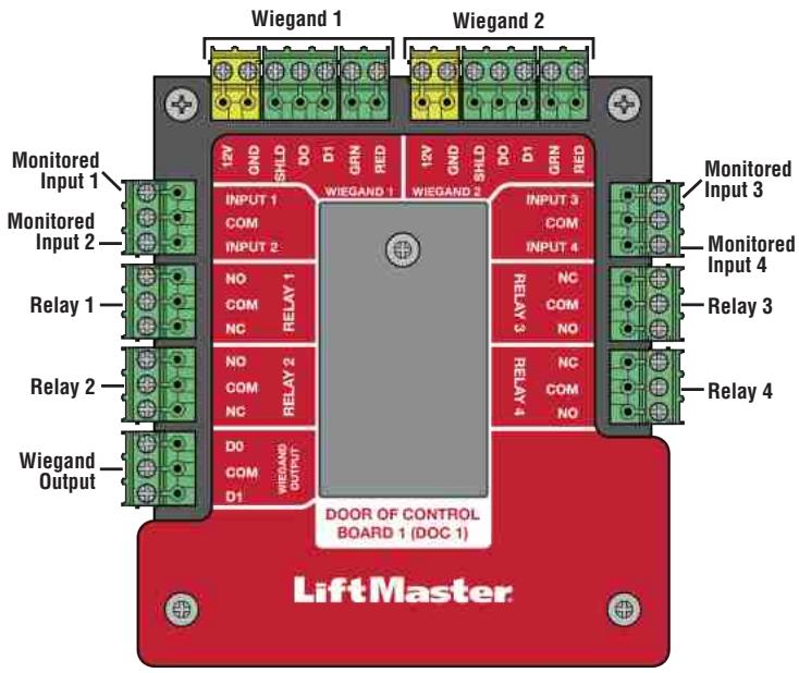
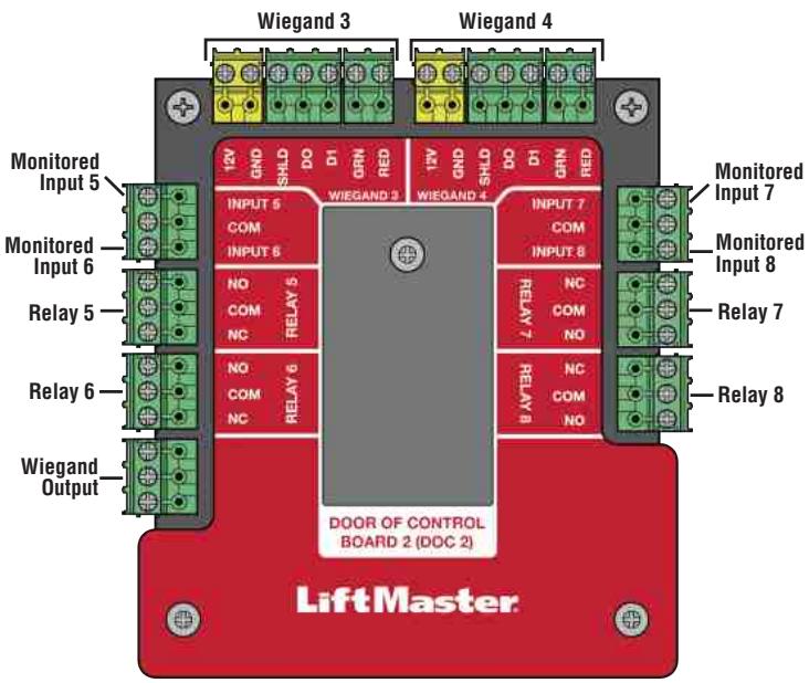
Door of Control Board Overview
The CAPXLV2 has a combination of access control inputs/outputs on the door of control board(s) that work in conjunction to control up to 4 access points each, so CAPXLV2 can control up to 8 access points in total.
CAUTION
DO NOT use the Wiegand 12V power output port to power anything except the Wiegand proximity readers.
NOTE: Monitored inputs can operate in any of the following configurations: Rex, knox box, or status.
| INPUT/OUTPUT | TYPE (CONFIGURABLE) | USED FOR |
| Monitored Inputs | REX (Request to Exit) | External Free Exit Loop Detectors, REX Buttons, and Proximity Sensors |
| Knox Box | In the case of an emergency (medical or fire), the Fire Rescue Department is able to gain entry. | |
| Status | Door sensors detecting when door is ajar. | |
| Supervised Gate Operators detecting when failed to close. | ||
| Supervised Gate Operators detecting when failed to open. | ||
| Relay | Gate Operator, Door Strikes, Alarm Shunt, Maglocks, and Lights (for control only - power to be provided by external supply) | |
| Wiegand Input | Proximity Readers (Wiegand 12Vdc power is for readers only, do not use to power other external devices). | |
| Wiegand Output | Access grant activity for integration with other access systems | |
NOTE: Only the 26-bit Wiegand protocol and OSDP protocol are compatible in UL installations.
Carton Inventory
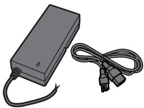
Power Supply
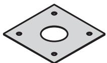
Goose-neck Gasket
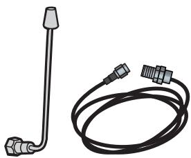
Radio Antenna (Security+ 2.0®) and Cable
S10K30MOV (Metal Oxide Varistor)(4)

Keys (2)

1N4005 Diode Kit (4)

100 Ohm 1/4 Watt Resistor (4)
Tools Needed
PH2 Phillips Screwdriver
Precision 1/8" Flat or PHO Phillips Screwdriver
1/4" Nut Driver
Drill/Driver
7/64" Drill Bit
- Hammer Drill Bits for Drill/Driver
RJ45 Crimping Pliers
Multimeter
- Measuring tape
Conduit Bender
Conduit Cutter/Reamer
- Hack Saw
Center Punch Tool
Hammer
ADDITIONAL TOOLS RECOMMENDED
Network LAN Cable Tester
Wi-Fi Analyzer App (smartphone app)
Network Analyzer software
Computer with Ethernet port
- Flat Head Screws for Mounting
Prepare for Installation from CAPXLV2
Be prepared by downloading and completing our Installation Readiness Survey. Assess current Internet connection details of the community site prior to new unit or upgrade of an installation, and identify action items needed to proceed. You can find this helpful tool at the following link: https://p.widencdn.net/oyeejd/114a4574.
Dimensions
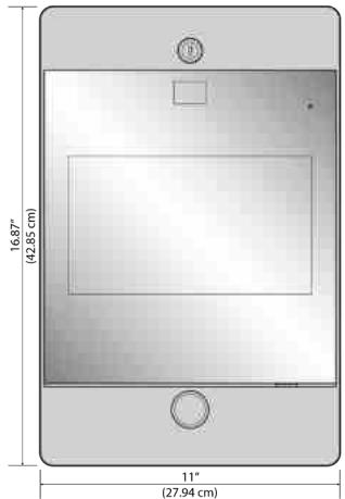
FRONT VIEW
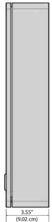
SIDE VIEW
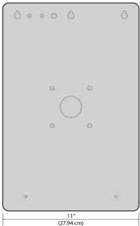
BACK VIEW
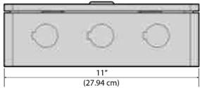
BOTTOM VIEW
Specifications
| Compliance | UL294 |
| CAPXLV2 Capacity | Resident Capacity 50,000 / Local Event History 50,000 |
| Supply Voltage 1 (VIN Connector) | 24V DC 72W (3A) MAX. The 24v power supply provided in the box is recommended. |
| Supply Voltage 3 (AC/DC converter) | 120 VAC, 1.5 A, 60 Hz |
| Supply Voltage 2 (POE) | 36-55VDC 60W max 802.3bt Type 3 four pair compatible max |
| PoE Supply Connector Configuration | Alternative B (or Mode B) |
| Operating Temperature | -20-50C |
| Storage and Shipping Temperature | -40-85C |
| Enclosure | Front (Aluminum), Rear (Carbon Steel) |
| Wiegand Inputs* (4) | 26-bit, *30-bit, *32-bit Mifare, *36-bit Mifare, *56-bit Mifare, *37-bit with and without facility code, and ASCII (for keyboards). 12VDC, 250mA power output (per input) |
| Relay Contacts (8) | SPDT 3A @ 30VDC (each) |
| OSDP | OSDP 2.2, 12 Vdc, 1.3 A max (total)OSDP Interface (1): connected up to 8 recommended OSDP readers in daisy chain configuration |
| Accessory Compatibility | Refer to the accessory page for compatible accessories |
| Network Compatibility | 10/100 Ethernet |
| Bluetooth® | Version 5.0 |
| Wi-Fi Compatibility | 802.11 a/b/g/n and 802.11ac 2.4GHz / 5GHz |
| Wi-Fi Security | CAPXLV2 is compatible with routers using the following security protocols: WPA3-SAE, WPA2-PSK/WPA3-SAE, WPA2-PSK, or WPA/WPA2-PSK |
| WiFi Range (w/ external antenna) | Up to 500 feet (152.4 m), Open Air/Line-of-Sight (range will vary depending on obstructions and 2.4GHz/5GHz router type) |
| Built-in Liftmaster Passport Receiver | Security+ 2.0 |
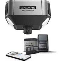
| Wireless Communication to Gate Operator | Up to 750 feet (228.6 m), Open Air/Line-of-Sight (range will vary depending on obstructions), Compatible with LiftMaster Security+ 2.0® gate operators, 2018 LiftMaster Gate Operators (firmware v4.4 and later), HD Operators (firmware v3.3 or later). NOT compatible with LiftMaster Barrier Gate Operators. |
| Video Camera | 1080p, Viewing angle - 135 degree diagonal, Up to 1,000 30-second temporary video events stored locally |
Wire Specifications
Use this chart to pull wires in preparation of your installation. Check the national and local building codes BEFORE installation.
| DESCRIPTION OF WIRE RUN | WIRE SPECIFICATION | MAXIMUM RUN DISTANCE |
| Recommended OSDP Reader (Up to 8 units daisy chained) | 22AWG. 2 twisted pairs (4 Conductor) (one pair for PWR/GND) (one pair for D0/D1) Shielded cable is optional terminated with 100 Ohms at each end. | 1000 feet (304.8 m) |
| Power Wire, 24V DC power supply | 2-Conductor 14 AWG | Up to 300 feet (91.4 m) |
| 2-Conductor 16 AWG | Up to 200 feet (60.9 m) | |
| 2-Conductor 18 AWG | Up to 100 feet (30.4 m) | |
| Local Area Network (LAN) CAT 5e or better Network Cable | 8-Conductor, 24 AWG Twisted pair | 328 feet* (100 m) |
| Grounding the Chassis (use grounding lug in CAPXLV2) | 12 AWG Copper | 12 feet (3.7 m) |
| Door Strike | 2-Conductor 18-22 AWG Shielded | 100 - 250 feet (30.5 - 76.2 m) |
| Magnetic Lock | 2-Conductor 18-22 AWG | 50 - 125 feet (15.2 - 38.1 m) |
| Dry Contact Closure (Most Gate Operators) | 2-Conductor 18-24 AWG Shielded | 500 - 2500 feet (152.4 - 762 m) |
| Exit Request (REX) | 2-Conductor 18-24 AWG | 500 feet (152.4 m) |
| Supervised Input | 2-Conductor 18-24 AWG | 500 feet (152.4 m) |
| Wiegand/Proximity Readers | 7-Conductor 18-22 AWG Shielded | 500 feet (152.4 m) |
| Postal Lock Box | 2-Conductor 18-24 AWG | 250 - 1000 feet (76.2 - 304.8 m) |
NOTE: Main power supply and control wiring MUST be run in separate conduits. Conduits must be UL approved for low and high voltage. Refer to the NEC for additional wiring requirements.
Category 5e cabling is the minimum performance category recommended.
Wiring shall be in accordance with the National Electrical Code (ANSI/NFPA 70), local codes and authorities having jurisdiction.
Always provide power from a dedicated source. Plug provided transformer into an outlet wired to its own 10 Amp minimum circuit breaker. This will prevent two problems:
- Other equipment cannot introduce spikes, noise, surges or dips into the power circuit that will affect the system.
- The system's operation will not be affected if any other equipment develops a short circuit across the power line.
* CAT 5e/6 NETWORK CABLE NOTES:
- For outdoor distances exceeding 140 feet (42.7 m), a UL497 compliant primary surge protector MUST be installed at the CAPXLV2.
- Distances exceeding 328 feet (100 m) may be accommodated with additional hardware (available through third-party sources).
The following services are required for CAPXLV2 to fully function
Setup a myQ® Community Account
NOTE: If you have an existing myQ® account, your myQ® Community account will have the same password. Go to: account.myQ.com and login.
If you do not have a myQ® Community account:

myQ
Method 1
- Call LiftMaster Customer Care at 877.247.6764 to create a myQ® Community account.
- You will get a welcome email from LiftMaster. Accept the invitation and register or login to your account.
- Setup the facility, select a subscription plan, add residents, and credentials (refer to the available Help in myQ® Community).
- Continue with the installation of the CAPXLV2 in this manual.
Method 2
- Navigate to account.myq.com.
- Click the Sign Up button.
- Follow on screen steps to set-up a facility, select Community Manager, or Dealer, select subscription plan, add residents, and credentials.
- Continue with the installation of the CAPXLV2 in this manual.
Sign up for myQ® Community Services
Service subscriptions are required for CAPXLV2 to fully function. To sign up for services:
- Set up a myQ Community account
a. Go to: account.myQ.com
b. If you don't have a myQ® account, choose Sign Up and follow the prompts to complete account signup.
c. If you have an existing myQ® account, your myQ® Community account will have the same password. Choose Log In.
- Create a new community
a. If you don't have any communities in your account, you will be prompted to create a new community. Follow the prompts to complete community creation.
- Add devices/subscription plan
a. Under Device Management, select CAPXLV2 and any other LiftMaster access control devices.
b. Subscription plan is pre-selected based on selected devices. Select any add-on services and check out.
c. Follow the prompts to finish adding CAPXLV2 and any other LiftMaster access control devices.
- Configure the community
a. Under People—People Management, add residents. Also make sure to assign at least one access group to each resident.
b. Under People—Mobile App License Management, assign myQ Community App licenses to residents.
c. For more, visit https://supportpartner.liftmaster.com/s/community-access-support/admins-and-community-managers.
- Continue with the installation of the CAPXLV2 in this manual.
For Support, call 877.247.6764 or visit https://supportpartner.liftmaster.com/s/community-access-support
NOTE: VoIP service is required for calling function. LiftMaster partners exclusively with Phone.com to provide the best integrated solution for voice and video calling. Other VoIP providers are not compatible with our CAPXLV2.

Remove Knockouts
- Turn the key clockwise to unlock the CAPXLV2.
- Open the door and lay the CAPXLV2 face down on a table with the door hanging off the edge of the table as shown.
- Identify which knockouts need to be removed based on your application.
- Use a center punch tool to remove the knockouts from the outside of the box inward using an appropriately sized punch and hammer.
NOTE: Be careful when removing the knockouts to avoid damaging the CAPXL V2 components.

CAUTION
To prevent damage to the CAPXLV2 from moisture or water:
- DO NOT install during rain. Internal components MUST be kept free from of water and moisture.
BEFORE opening the front cover of the CAPXLV2, remove ANY accumulated water from the top of the CAPXLV2.
To prevent damage to ANY internal components:
- DO NOT attempt to remove the knockouts with a hammer. Banging on the knockouts may result in shock to the circuit boards, which could cause permanent damage.
- Some internal wires may be close to the knockouts. Make sure to move any wire away from knockouts.
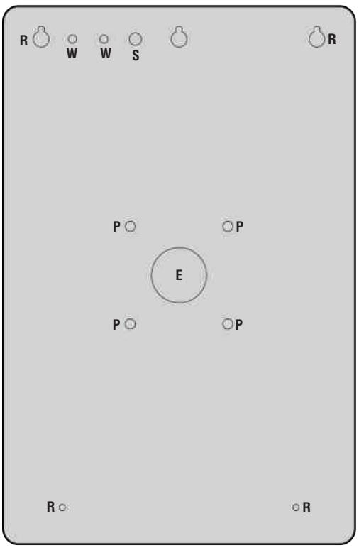
E = Electrical Wiring
P = Pedestal Mount
R = Recess Mount
S = Radio Antenna
W = Wi-Fi^® Antenna

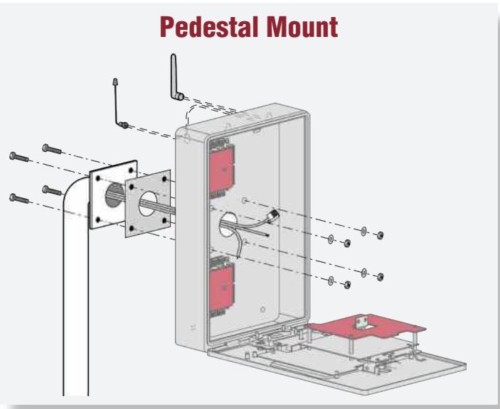
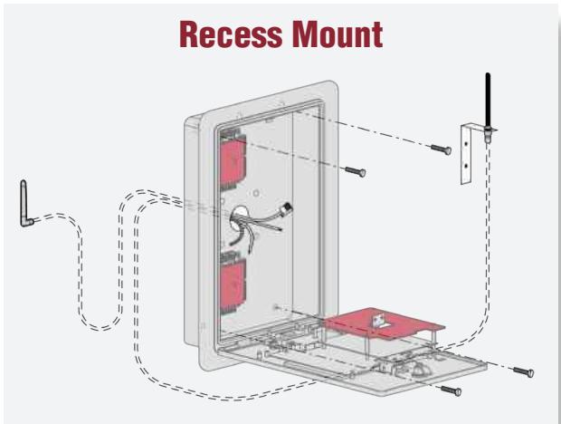
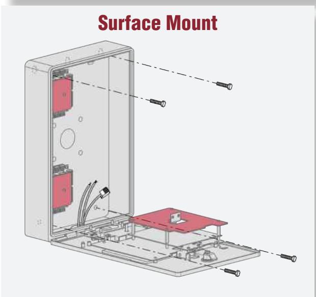
Mount CAPXLV2
- Attach the goose-neck gasket (provided) if mounting to a goose-neck.
- Mount the CAPXLV2 securely to a flat surface or pedestal with appropriate hardware taking care to route wiring through appropriate knockouts. Stainless steel hardware is recommended to mount the CAPXLV2. Use of zinc plated or galvanized hardware is at risk for galvanic corrosion.
D0
Make sure any internal wiring is inside the chassis before you close the front panel of CAPXLV2 to prevent any moisture from entering the chassis.
NOTES:
- Ensure the cover can fully open to allow access after the installation is complete.
- ADA Compliance: When mounting the CAPXLV2 at a pedestrian entrance, to meet ADA compliance, mount the top of the CAPXLV2 screen no higher than 54 inches from the ground.
- Do Not exceed a Max Bolts Length of 1.5" for Pedestal Mount Security Bolt.
- For surface and recess mounting, please use appropriate bolt length that secures CAPXLV2 to the surface completely. The length will vary with the surface of the wall.
- When mounting the CAPXLV, refer to the recommended screw quantity, type, length, and diameter in the table.
| MOUNTING CONFIGURATION | QUANTITY | TYPE/LENGTH/DIAMETER |
| Pedestal Mount | 4 | Metal/28.62mm/6.11mm |
| Recess/Surface Mount | 4 | Metal/Length*/4.12mm |
*For Recess/Surface Mount applications, the recommended screw lengths are 13.54mm, 16.56mm, 19.72mm, and 22.76mm.

Install Antennas
The Security +2.0^© radio antenna and Wi-Fi® antennas must be a minimum of 8 inches (20 cm) apart. Install the antennas on opposite sides of the CAPXLV2. Optional antenna cable kits are available for remote antenna mounting (refer to accessories).
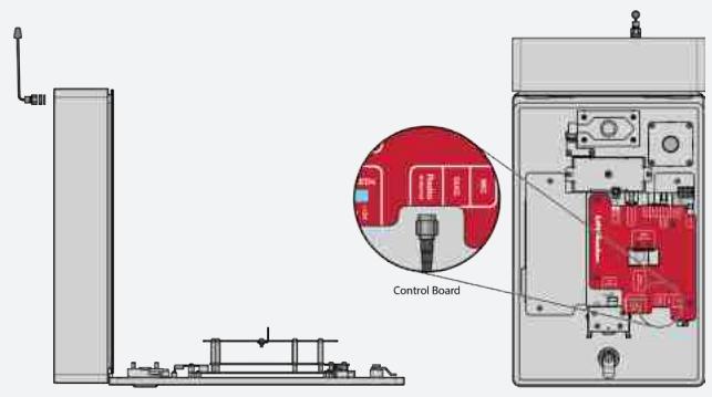
Security+ 2.0® Radio Antenna (if applicable), (included in the package)
Used with LiftMaster Passport Security+ 2.0^® and wireless communication with LiftMaster UL325 2016 compliant gate operators.
- Remove 3/8 knockout on the back of the CAPXLV2.
- Secure the radio antenna to the desired knockout on the CAPXLV2.
- Connect the radio antenna cable to the main board as shown.
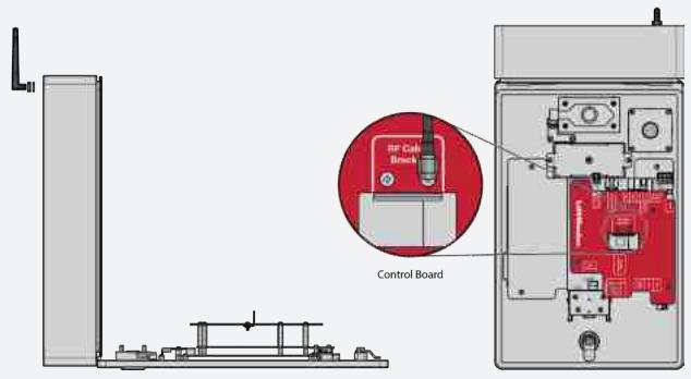
Wi-Fi® Antenna (if applicable), (optional accessory WFBTEXT)
Used for Wi-Fi® Internet.
- Remove 1/4 knockout on the back of the module.
- Secure the Wi-Fi® antenna to the desired knockout on the CAPXLV2 with the provided gasket, washer, and nut.
- Connect the Wi-Fi® antenna cable to the main board as shown.

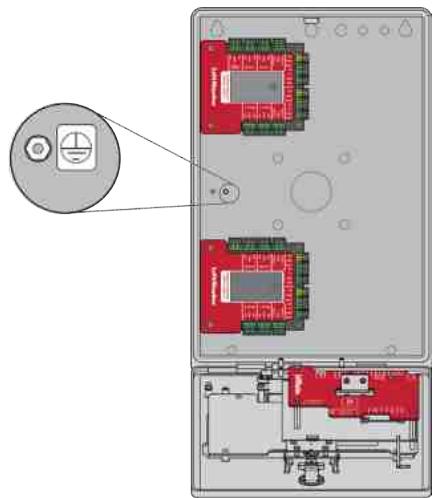
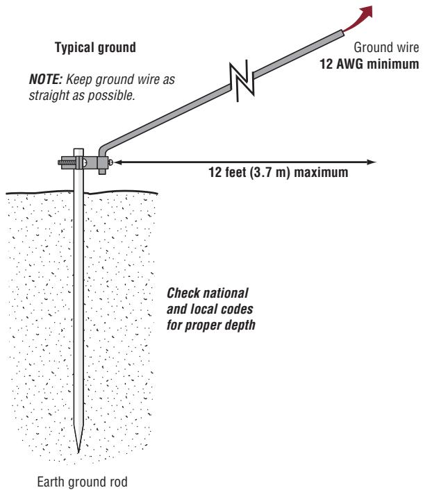
Ground the Unit
IMPORTANT: CAPXLV2 must always be connected to earth ground, whether by an earth ground rod or other means. An earth ground rod is strongly recommended and should be no further than 12 feet (3.7 m) from the CAPXLV2 and use a minimum of 12 gauge wire in most cases. The type and length of earth ground rods vary by region. Contact the AHJ (Authority Having Jurisdiction) in the municipality where you plan to install the CAPXLV2 for correct grounding materials and installation procedures. A proper ground is critical to minimizing risk for the CAPXLV2 from damaging electrical transients.
- Connect the ground wire (12 AWG or larger) to the CAPXLV2 main earth ground connection.
- Run the wire from the CAPXLV2 to suitable earth ground.
NOTE: Shield connections on boards should not be connected to main earth ground connection.

CAUTION
- To AVOID damaging gas, power or other underground utility lines, contact underground utility locating companies BEFORE digging.
- Use the PoE injector or router/switch with PoE PSE capability that complies with 802.3bt (Type 3 four wire class 5 compatible) and UL294 with output power as 36-55V and 45 W(Max) per port.
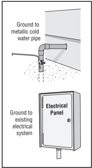
Other ground sources within 12 feet of access control panel
5 Connect Power
USING A DC POWER SUPPLY:
The outlet for the CAPXLV2 MUST be an external dedicated 120 Vac outlet. Refer to the table below for maximum wire run distances. This outlet should be wired back to its own 10 Amp minimum circuit breaker.
| WIRE SPECIFICATION | MAXIMUM RUN DISTANCE |
| 14 AWG | Up to 300 feet (91.4 m) |
| 16 AWG | Up to 200 feet (60.9 m) |
| 18 AWG | Up to 100 feet (30.4 m) |
- Connect 14-18 AWG wire to the stripped secondary DC output wires on the power supply. Black is negative and red is positive.
- Remove the PWR INPUT terminal block from the Power/Internet Board.
- Connect the power supply wires to the PWR INPUT terminal block (red to +24V and black to GND). Reattach the terminal block to the Power/Internet Board.
- Plug the power supply into a 120 Vac outlet after all connections have been made.
NOTE: The green LED on the door of control board will blink and the green LED on the Power/Internet Board will light solid when powered up. The CAPXLV2 will display the LiftMaster logo while booting up. When boot up is complete, the user interface will appear.
- Close the CAPXLV2 door.
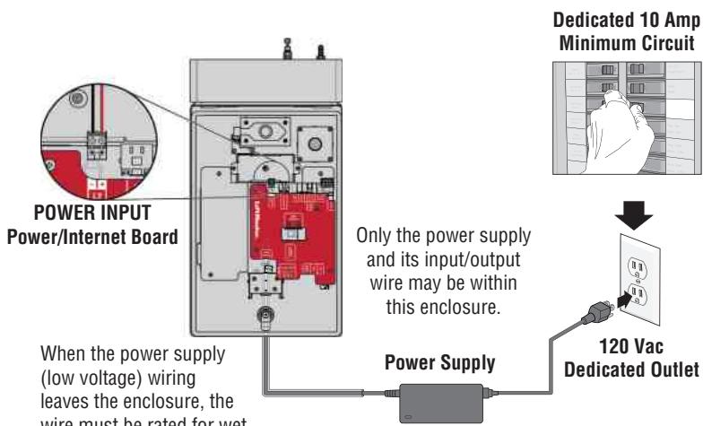
When the power supply (low voltage) wiring leaves the enclosure, the wire must be rated for wet and damp locations.
High voltage wiring must be run in a separate conduit from low voltage wiring.
NOTE: If the power supply is installed outdoors, the power supply must have its own approved NEMA 4 Rated weatherproof electrical enclosure. Use conduit from the power supply enclosure to the controller enclosure.
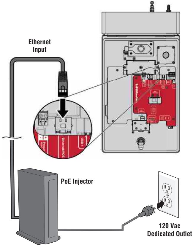
USING PoE (POWER OVER ETHERNET):
Connect Ethernet cable to the LAN/PoE connection on the main board.
CAUTION
- DO NOT use ANY power supply other than those supplied with your CAPXLV2.
- Use the PoE injector or router/switch with PoE PSE capability that complies with 802.3bt (Type 3 four wire class 5 compatible) and UL294 with output power as 36-55V and 45 W(Max) per port.
- DO NOT power electronic strikes and latches with the same power supply used to power the access control panel; doing so will cause DAMAGE to the CAPXLV2. Use ONLY a UL listed burglar alarm or access control system to power electronic strikes and latches.
- DO NOT connect the power supply or PoE injector to a switched outlet or otherwise controlled AC outlet.
- DO NOT connect the power supply to the 120 Vac outlet until ALL wiring is completed.
- DO NOT connect the PoE enabled RJ45 Ethernet cable until ALL wiring is connected, if PoE is used.
- Install the transient noise suppression device (MOV) supplied with the CAPXLV2 for AC powered devices and Diode for DC powered devices.
- DO NOT connect the 24V power supply and POE power supply to the device at the same time.
- If the power supply has a ground wire, then it must be wired to the GND terminal block to ensure effective grounding.
1 Connect Internet The CAPXLV2 can connect to the Inter
The CAPXLV2 can connect to the Internet with a wired Ethernet connection or with Wi-Fi® (wireless). Make sure you are in the Admin Mode before you connect to the Internet. If you are not in Admin Mode, press the 3 dots in the upper right corner of the CAPXLV2 display and enter the Admin Code, enter the password (default is 888888), press the Network tab on the CAPXLV2 display, and press the "Change Network Settings" button. Follow the instructions according to your application.
OPTION 1 Wired Connection
The Local Area Network (LAN) port is a 10/100 Ethernet interface with an RJ45 jack for connecting the CAPXLV2 to a hub, switch, or router in order for it to gain connectivity to the Internet. Use a straight, (i.e., non-crossover) Cat5e, or Cat6 cable to connect to a local hub, switch or router. This type of cable is referred to as an Ethernet cable in this manual.
- Plug the input Ethernet cable into the main board.
- Connect an Ethernet cable from the hub, switch, or router to the LAN port on the main board. When connected properly, the green and amber LED on the Ethernet port of the main board will light/flicker (the main board is located on the back of the CAPXLV2 display). If the green LED is not lit, check the connections on the CAPXLV2 and the Ethernet hub.
- On the display, select Wired Network if dynamic configuration (DHCP) is desired or select Manual Setup for a static IP address.
OPTION 2 Connect through Wi-Fi® (Wireless)
- On the display select Wi-Fi® Network.
- Select the network the CAPXLV2 will use.
- Enter the password for the network.
- Select Login.
Additional compatibility considerations:
- When checking signal strength in CAPXLV2 admin mode, at least two bars are recommended.
- Use accessory WFBTEXT (WiFi® External Antenna Kit) and WFAEXT (15' WiFi® Extension Kit) to move the CAPXLV2 antenna higher up or to a location resulting in two or more bars.
- If using a Wi-Fi® signal strength tool or app, a continuous Wi-Fi® signal strength connection of at least -65 DBM (numbers closer to zero are stronger strength) at the CAPXLV2 must be guaranteed to ensure an acceptable connection to the local network.
- Hidden network SSID's are not supported. The network must be selectable from the CAPXLV2 display.
- Wi-Fi® networks requiring secondary authentication are not supported (E.g. Hotels and airport Wi-Fi®).
2 Validate Setup
On the display, select each tab in Admin Mode to validate setup (network, inputs, outputs, etc.). Once you have validated the setup, exit Admin Mode.
Gate Access (Wired)
Disconnect power BEFORE making electrical connections. Below is an example of a wiring setup for gate access. Gate access can be wired to Relay 1, 2, 3, or 4 on the Door of Control Board. LiftMaster® Security+ 2.0^® gate operators can also be programmed to communicate wirelessly instead of using a wired connection (refer to the following page). Input and output port functions on CAPXLV2 can be configured via the myQ Community web portal. Below is an example use case of connections to various external devices.
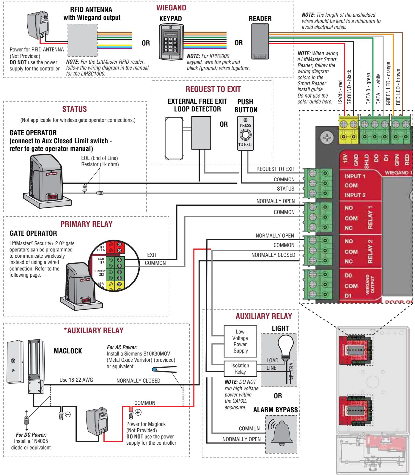
* NOTE: MAGLOCK and ALARM
BYPASS not evaluated by UL.
Gate Access (Wireless)
The CAPXLV2 can communicate wirelessly to LiftMaster® UL325 gate operators to send open commands, monitor gate position, and send email notifications if an error occurs in the operator (email notifications are configured in myQ®). Up to 8 gate operators can be paired with the CAPXLV2 - one for each relay. If using dual gates, program the CAPXLV2 to the primary operator.
NOTE: Use of this feature requires the optional Passport antenna kit.
1 Enter Admin Mode
Press the 3 dots in the upper right corner of the CAPXLV2 display and enter the Admin Code
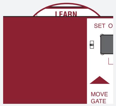
2 Select Outputs and Relay
Select the Outputs tab. Then select the desired relay on the left-hand side (1 through 8).
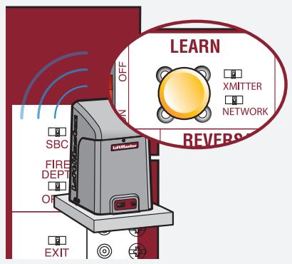
3 Press LEARN button on gate operator
Press and release the LEARN button on the primary operator. The green XMITTER LED will light. NOTE: The operator will time out of programming mode after 180 seconds.
4 Press LEARN button on gate operator again
Press and release the LEARN button again on the primary operator. The yellow NETWORK LED will light.
5 Select LEARN on display
Select the LEARN button on the display and the Learn button will go from blue to red. The gate operator will beep once, CAPXLV2 learn button will change to "Unlearn", and the NETWORK LED on the gate operator will turn off, indicating programming is successful.
NOTE: 4 beeps/blinks indicate you are not programming to the primary operator. Reattempt programming from the other operator.
6 Validate
Validate functionality by selecting Test Relay on the CAPXLV2 display.
Door Access
Disconnect power BEFORE making electrical connections. Below is an example of a wiring setup for door access. Door access can be wired to Relay 1, 2, 3, or 4 on the Door of Control Board. Input and output port functions on CAPXLV2 can be configured via myQ Community web portal. Below is an example use case of connections to various external devices.
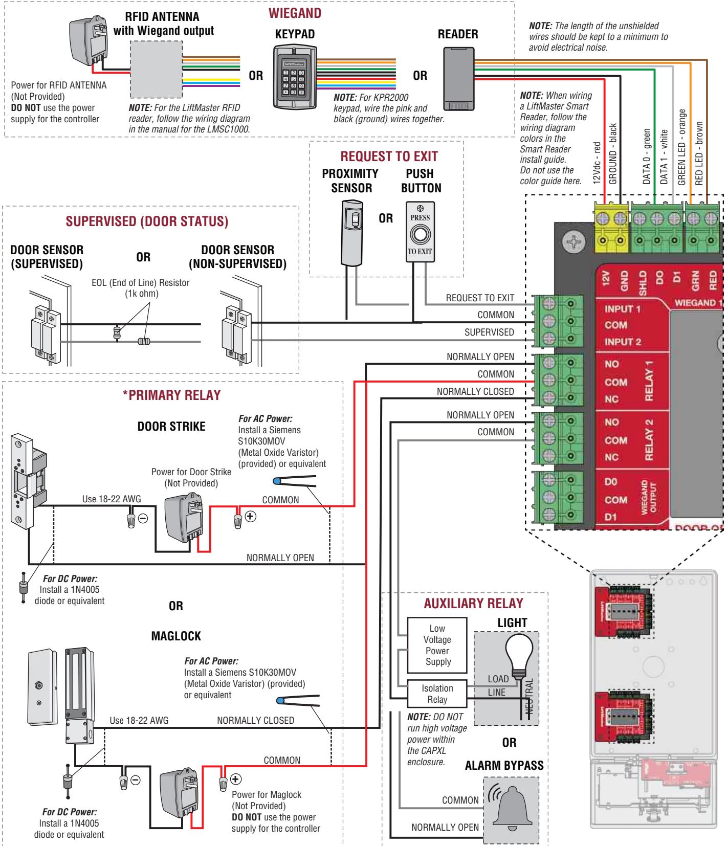
* NOTE: MAGLOCK, door strike
and ALARM BYPASS not
evaluated by UL.
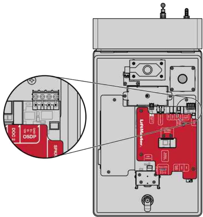
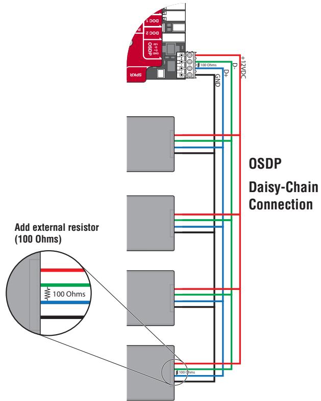
OSDP Card Reader
The CAPXLV2 is designed to connect a single or multiple OSDP readers. The OSDP reader should be installed by following the following steps:
- Disconnect power from the CAPXLV2.
- Prepare RS-485 cables before the connection by adding the matching resistors (100 ohms) to both ends of the cable.
- Connect one end of the RS-485 cables and 12VDC power to the OSDP connector on the CAPXLV2 main board.
- Turn on power of CAPXL2 and make sure it is in Admin mode.
- Go to OSDP Tab in Admin Mode.
- Toggle Enable Install New Reader.
- Make sure the new OSDP reader has default address 0 by following the manufacturer's recommendation. If not, connect the OSDP reader to 12V power line and GND, using configuration card (5044-FEA-OSDP-018) to set to manufacture default and then disconnect 12V power line.
- Connect the new OSDP reader to RS-485 cables.
- The CAPXLV2 should discover the connected reader and create the reader in myQB. The reader should turn its LED to amber and beep three times. The OSDP reader is now installed.
- To install more OSDP readers, follow steps 7 through 9 for each new OSDP reader.
The uninstallation or deletion of the OSDP should follow the following steps:
- Make sure the OSDP reader to be deleted is connected to RS-485.

WARNING
Never disconnect OSDP reader before uninstalling or deleting from Admin UI.
- Go to Tab in Admin mode
- Selected the OSDP reader to be deleted from the Connected Readers
- Click Delete Button.
- Click Delete in the confirmation pate
- Check if the deleted reader is not displayed under Connected Readers.
- Disconnect the deleted reader from RS485 cable and 12V power line.

CAUTION
CAPXLV2 can only install one OSDP reader at a time. You must complete steps 7 through 9 for an OSDP reader before you connect another new OSDP reader to the RS-485 cables.
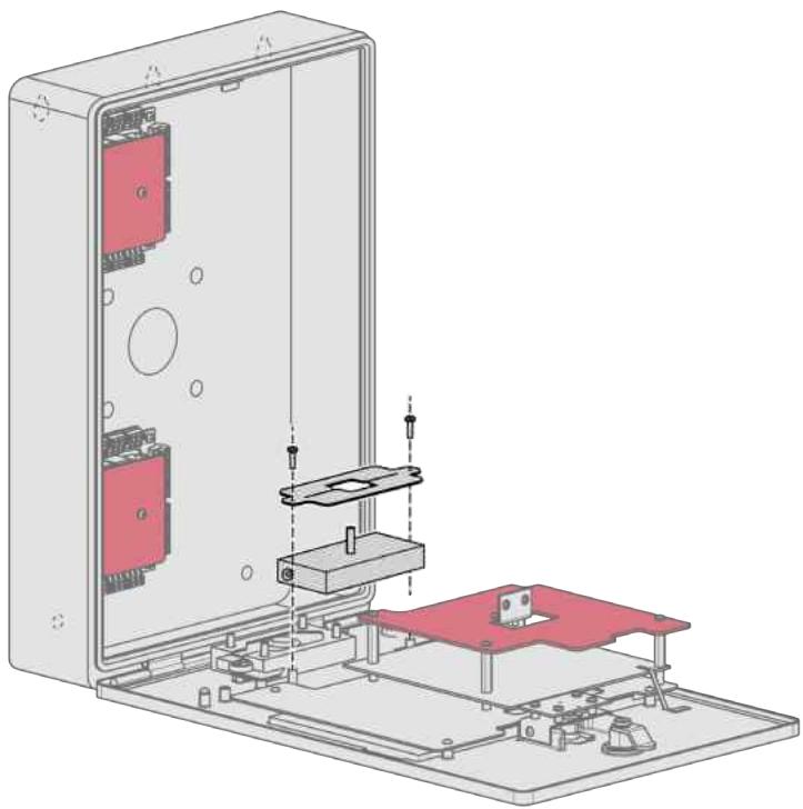
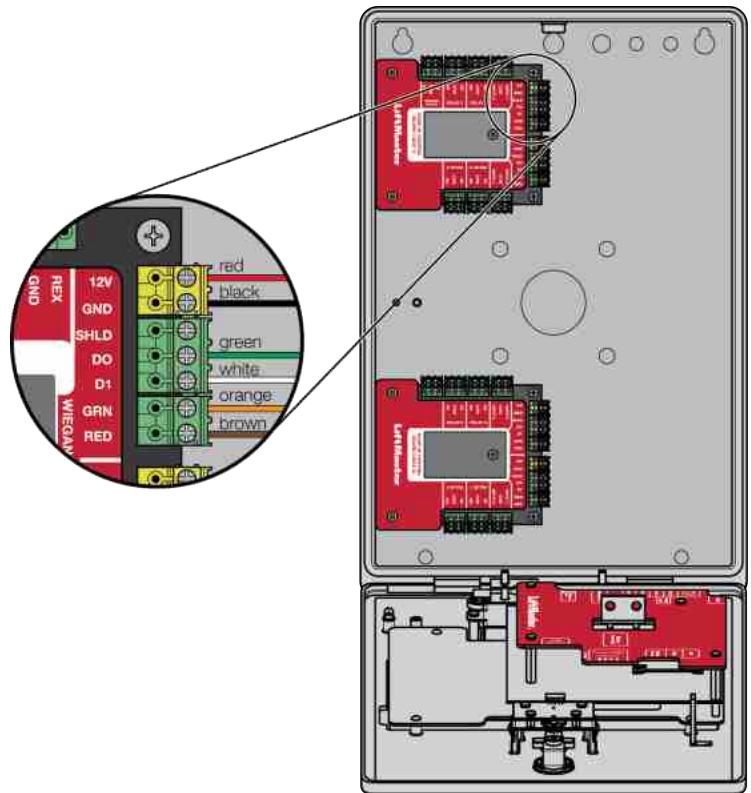
Wiegand Card Reader
The CAPXLV2 is designed to fit multiple readers on the flexible reader mount inside the chassis.
- Disconnect power from the CAPXLV2.
- Secure the Reader to the Mounting Plate with the supplied screws.
- Place the reader against the glass in the CAPXLV2.
- Secure the Reader and Mounting Plate assembly into the CAPXLV2 with two screws in the side wings.
- Apply silicon around the cable hole.
- The reader can be wired to any of the 4 Wiegand Inputs on the door of control board(s). Insulate any unused wires from the CAPXLV2 to prevent a short. (Refer to instructions provided with your Reader for more information.)
- Reconnect power to the CAPXLV2.
- Refer to myQ® for programming.
READER BRACKET
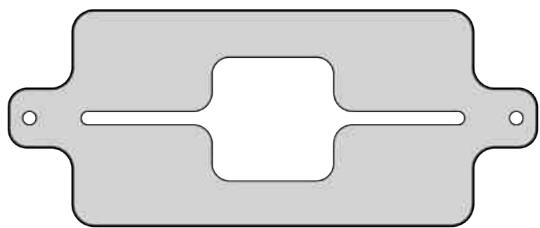
NOTE: To fit the mounting plate and the cavity, the reader dimensions can not exceed 4'' × 2'' .
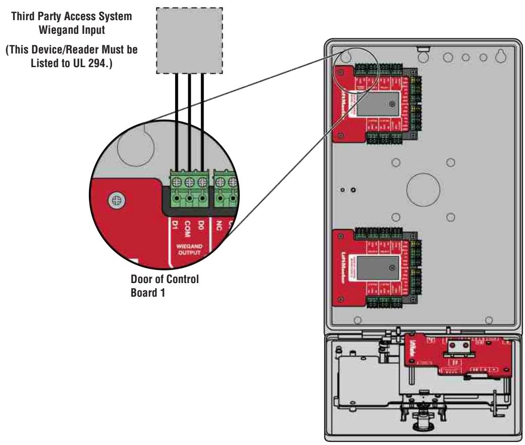
Wiegand Output
Disconnect power BEFORE making electrical connections. The CAPXLV2 offers a Wiegand output capable of 26 bit transmission of the following data:
- Success Call with access granted by the resident. The CAPXLV2 will provide a myQ® Community specified facility code followed by the Directory Code of the resident that granted access.
And/Or
- Successful access through Entry Code. The CAPXLV2 will provide a myQ® Community specified facility code followed by the successful Entry Code.
And/Or
- Successful access with a credential. The CAPXLV2 will pass along the successful credential Facility Code and ID.
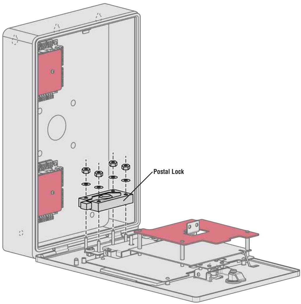
Postal Lock
- Remove the wing nut and plug. Discard the wing nut and plug.
- Remove 4 mounting nuts from studs.
- Install postal lock using 4 nuts from step 2.
- Cut the factory installed wire tie from the postal lock switch.
The postal lock switch is wired from the factory.
NOTE: The postal lock cable length shall not exceed 98.5 ft (30 m).
CAUTION
- Not responsible for conflicts between the information listed in the wiring diagram and the requirements of your local building codes. The information is for suggested use ONLY. Check your local codes BEFORE installation.
- DO NOT connect the 24V power supply and POE power supply to the device at the same time.
Repair Parts
| ITEM | PART NUMBER |
| Door of Control Board And Covers | K41-0422-000 |
| Main Board Kit | K41-0366-000 |
| Reader Mounting Plate Kit | K41-0367-000 |
| Rear Housing Assembly Kit | K41-0368-000 |
| Wiring Kit | K41-0369-000 |
| Speaker Kit | K41-0370-000 |
| Front Panel and Display Kit | K41-0371-000 |
| Postal Lock Switch | K41-0219-000 |
| Cam Lock and Kit | K41-0215-000 |
Accessories
| ITEM | PART NUMBER |
| Flush Mount Trim Kit | CAPXLV2TK |
| Hood for Pedestal and Surface Mount Applications | CAPXLV2HOOD |
| Trim Plate and Hood Together | CAPXLV2TKHD |
| Power Supply | K41-0227-000 |
| USB Camera Kit | CAPXLCAM |
| Radio Antenna Extension (15 foot) | G86LM |
| Wi-Fi® Antenna Extension (15 foot) | WFAEXT |
| Wi-Fi/Bluetooth® Extension Antenna | WFBTEXT |
| ESARM Antenna | XMANTKIT |
| UHF Long Range RFID Reader | LMSC1000 |
| Wiegand Keypad/Proximity Reader | KPR2000* |
| LiftMaster Smart Reader and Keypad with OSDP Support | SRDRST or SRDRKP |
| Connected Access Portal 2 Door | CAP2D |
| Passport 3-Button Visor Control MAX | PPV3M |
| Passport 3-Button Mini Remote Control MAX | PPK3M |
| Passport 3-Button Mini Proximity Remote Control MAX | PPK3PHM |
| Passport Lite 1-Button Visor Remote | PPLV1-X** |
| Passport Lite 1-Button Key Chain Remote | PPLK1-X** |
| Passport Lite 1-Button Mini Proximity Remote | PPLK1PH-X** |
- KPR2000 verified for supplementary use only
** Available in 10 and 100 packs, replace X with 10 or 100
NOTE: If you have a specific model of reader or keypad that is not listed on the LiftMaster website, please contact LiftMaster Technical Support to determine compatibility.
Configuration Sheet
Record device information and configuration settings below.
CAPXLV2 Name:
NOTE: Any user of the system is subject to the terms outlined in the product EULA.
Notes:
DEVICE CONFIGURATION:
| Access Point 1 | ||||
| Door/Gate Name: | ||||
| Inputs | Type | Input Name | EOL (Y/N) | Hardware Mapping |
| First Monitored Input | ||||
| Second Monitored Input | ||||
| Third Monitored Input | ||||
| Fourth Monitored Input | ||||
| Relays | Type | Relay Name | N.O./N.C. | N.O./N.C. |
| First Relay | ||||
| Second Relay | ||||
| Readers | Type | Reader Name | Hardware Mapping | |
| First Reader | ||||
| Second Reader | ||||
| Notes: | ||||
| Access Point 2 | ||||
| Door/Gate Name: | ||||
| Inputs | Type | Input Name | EOL (Y/N) | Hardware Mapping |
| First Monitored Input | ||||
| Second Monitored Input | ||||
| Third Monitored Input | ||||
| Fourth Monitored Input | ||||
| Relays | Type | Relay Name | N.O./N.C. | N.O./N.C. |
| First Relay | ||||
| Second Relay | ||||
| Readers | Type | Reader Name | Hardware Mapping | |
| First Reader | ||||
| Second Reader | ||||
| Notes: | ||||
Legal Disclaimers
Federal Communications Commission (FCC) Compliancy
This equipment has been tested and found to comply with the limits for a Class B digital device, pursuant to Part 15 of the FCC Rules. These limits are designed to provide reasonable protection against harmful interference in a residential installation or when the equipment is operated in a commercial environment. This equipment generates, uses and can radiate radio frequency energy and, if not installed and used in accordance with the instruction manual, may cause harmful interference to radio communications. However, there is no guarantee that interference will not occur in a particular installation. If this equipment does cause harmful interference to radio or television reception, which can be determined by turning the equipment off and on, the user is encouraged to try to correct the interference by one or more of the following measures:
- Increase the distance between the equipment and receiver.
- Connect the equipment to a circuit other than the one to which the receiver is connected.
Consult the dealer for help.
Canada-Underwriters Laboratories Compliance
The CAPXLV2 shall be installed in accordance with Part 1 of the Canadian Electrical Code.
Documentation Disclaimer and Restrictions
Information in this document is subject to change without notice and does not represent a commitment on the part of LiftMaster. For the most up-to-date information, visit LiftMaster.com.
This document and the data herein shall not be duplicated, used or disclosed to others for procurement or manufacturing, except as authorized with the written permission of LiftMaster. The information contained within this document or within the product itself is considered the exclusive property of LiftMaster. All information in this document or within the hardware and software product themselves is protected by the copyright and/or other intellectual property laws of the United States.
UL 294 Access Control Unit Endurance: Level 4, Mobile Credential Endurance Level II by using Mobile phone Bluetooth 25,000 cycles, Line security: Level 1, Destructive Attack: Level 1, Power Standby: Level 1
NOTICE: This device complies with part 15 of the FCC rules and Innovation, Science and Economic Development Canada licence-exempt RSSs. Operation is subject to the following two conditions: (1) this device may not cause harmful interference, and (2) this device must accept any interference received, including interference that may cause undesired operation. Any changes or modifications not expressly approved by the party responsible for compliance could void the user's authority to operate the equipment.
This device must be installed to ensure a minimum 20 cm (8 in.) distance is maintained between users/bystanders and device.
This device has been tested and found to comply with the limits for a Class B digital device, pursuant to part 15 of the FCC rules and Industry Canada ICES standard. These limits are designed to provide reasonable protection against harmful interference in a residential installation. This equipment generates, uses and can radiate radio frequency energy and, if not installed and used in accordance with the instructions, may cause harmful interference to radio communications.
However, there is no guarantee that interference will not occur in a particular installation. If this equipment does cause harmful interference to radio or television reception, which can be determined by turning the equipment off and on, the user is encouraged to try to correct the interference by one or more of the following measures:
- Reorient or relocate the receiving antenna.
- Increase the separation between the equipment and receiver.
- Connect the equipment into an outlet on a circuit different from that to which the receiver is connected.
- Consult the dealer or an experienced radio/TV technician for help.
*NOTE: When installing CAPXLV2 please refer to the local jurisdiction for any specific requirements such as physical signage that may be required.
Wi-Fi® is a registered trademark of Wi-Fi Alliance®.
myQ® Community
Interphone video intelligent L
MANUEL D'INSTALLATION
Modèle CAPXLV2