CAP2D - Security and Access Control System LIFT-MASTER - Free user manual and instructions
Find the device manual for free CAP2D LIFT-MASTER in PDF.
| Brand | LIFT-MASTER |
| Model | CAP2D |
| Product Type | Connected 2-door/gate access controller |
| Usage | Residential and commercial access control |
| User Capacity | 25,000 residents, local history of 6,000 events |
| Wiegand Inputs | 2 inputs (26-bit SIA, 30-bit Sentex, 32-bit Mifare, 37-bit HID, ASCII) |
| Relay Outputs | 2 primary SPDT + 2 auxiliary SPDT (3 A max, 24 VDC) |
| Power Supply | 12 VDC auxiliary (13 W) or PoE 44-57 VDC (13 W) |
| PoE | Yes, IEEE 802.3af/at (not UL evaluated) |
| Network Connection | Ethernet 10/100, RJ-45, DHCP or static IP |
| Operating Temperature | -35 °C to 66 °C |
| Operating Humidity | 5% to 95% non-condensing |
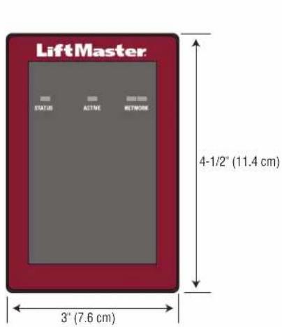
| Dimensions (approx.) | 10.2 x 10.2 x 3.8 cm (mounts on 4-inch box) |
| Weight (approx.) | 0.5 kg |
| Warranty | 2-year limited |
| Standards | UL294, FCC Part 15 Class B, ICES-003 |
| Included Accessories | USB cable, diodes, installation manual |
| Software Features | myQ® Business™ for remote management and monitoring |
| Safety | Professional installation, disconnect before servicing, varistor included |
| Installation | Mount on 4-inch electrical box, separate wiring for power and control |
Frequently Asked Questions - CAP2D LIFT-MASTER
User questions about CAP2D LIFT-MASTER
0 question about this device. Answer the ones you know or ask your own.
Ask a new question about this device
Download the instructions for your Security and Access Control System in PDF format for free! Find your manual CAP2D - LIFT-MASTER and take your electronic device back in hand. On this page are published all the documents necessary for the use of your device. CAP2D by LIFT-MASTER.
USER MANUAL CAP2D LIFT-MASTER
Connected Access Portal 2-Door Controller
INSTALLATION MANUAL
Model CAP2D
LiftMaster®
INTRODUCTION
i
Safety 3
Controller Overview 4
Control Board Overview 4
Carton Inventory 5
Tools Needed 5
Dimensions 5
Specifications 6
Electrical Ratings 6
Wire Specifications 7
PRE-INSTALL
Internet Service 8
CP# for Controller 8
Setup a myQ® Business™ Account 8
Mount the Bracket. 9
myQ
business
2 WIRING
Connect Power 10

3 NETWORK
Connect Internet 11


4 ACCESS CONTROL
Admin Mode. 12
Wiring REX and Doors 12
Operation 14
Gate Access. 15
Door Access. 16
5 INSTALL
Install the CAP2D 17
Troubleshooting 18
Configuration Sheet 18
Legal Disclaimers 19
Warranty 19


Warranty 19

Safety
Safety Symbol and Signal Word Review
When you see these Safety Symbols and Signal Words on the following pages, they will alert you to the possibility of serious injury or death if you do not comply with the warnings that accompany them. The hazard may come from something mechanical or from electric shock. Read the warnings carefully.
When you see this Signal Word on the following pages, it will alert you to the possibility of damage to your property or product if you do not comply with the cautionary statements that accompany it. Read them carefully.

WARNING
MECHANICAL

WARNING
ELECTRICAL

CAUTION


WARNING
To reduce the risk of SEVERE INJURY or DEATH:
- Disconnect power at the fuse box BEFORE proceeding.
- To AVOID damaging gas, power or other underground utility lines, contact underground utility locating companies BEFORE digging.
- ALL electrical connections MUST be made by a qualified individual.
- ALL power and control wiring MUST be run in separate conduit.
To protect against fire and electrocution:
- Disconnect power BEFORE installing or servicing controller.
- NEVER connect a keypad/reader or lock to doors without first consulting the applicable fire code.
- You MUST consult with, and get approval from, local fire officials BEFORE installing locks or devices on ANY doors that may be fire exits.
- Use of egress push buttons may not be legal. Single action exits may be required.
- ALWAYS obtain proper permits and approvals in writing BEFORE installing equipment.

WARNING: This product can expose you to chemicals including lead, which are known to the State of California to cause cancer or birth defects or other reproductive harm. For more information go to www.P65Warnings.ca.gov.
UNDERWRITERS LABORATORIES (UL) COMPLIANCE
The CAP2D complies with the UL294 Standard for access control units with the following restrictions:
- The system relay contacts shall not be configured in the fail secure mode unless permitted by the local authority having jurisdiction and shall not interfere with the operation of panic hardware.
- The Ethernet port is for supplemental use only, the unit will continue to operate standalone if the network connection is interrupted.
This unit can be powered over Ethernet via PoE Compatible hardware. Where used, any PoE power source must be UL294 Listed.
All interconnecting devices must be UL Listed.

WARNING
DO NOT INSTALL THE SYSTEM IN THE FAIL SECURE MODE UNLESS PERMITTED BY THE LOCAL AUTHORITY HAVING JURISDICTION. Doing so may cause interference with the operation of panic hardware.
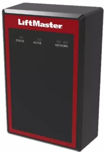
Controller Overview
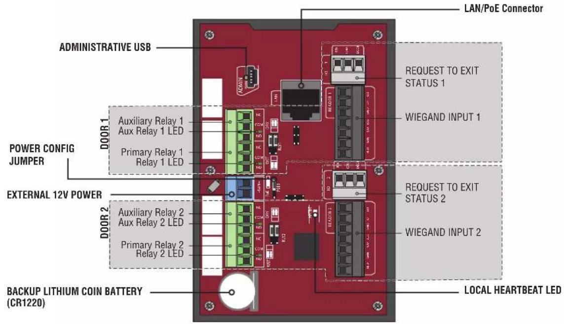
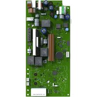
Control Board Overview
| Control Board Connection Description | |
| Administrative USB Connect Mini-USB | cable to access administrative functions |
| LAN/PoE Connect to network. *May also carry 802.3af/at power | |
| Backup Lithium Battery Battery preserves the system's data during primary power outages | |
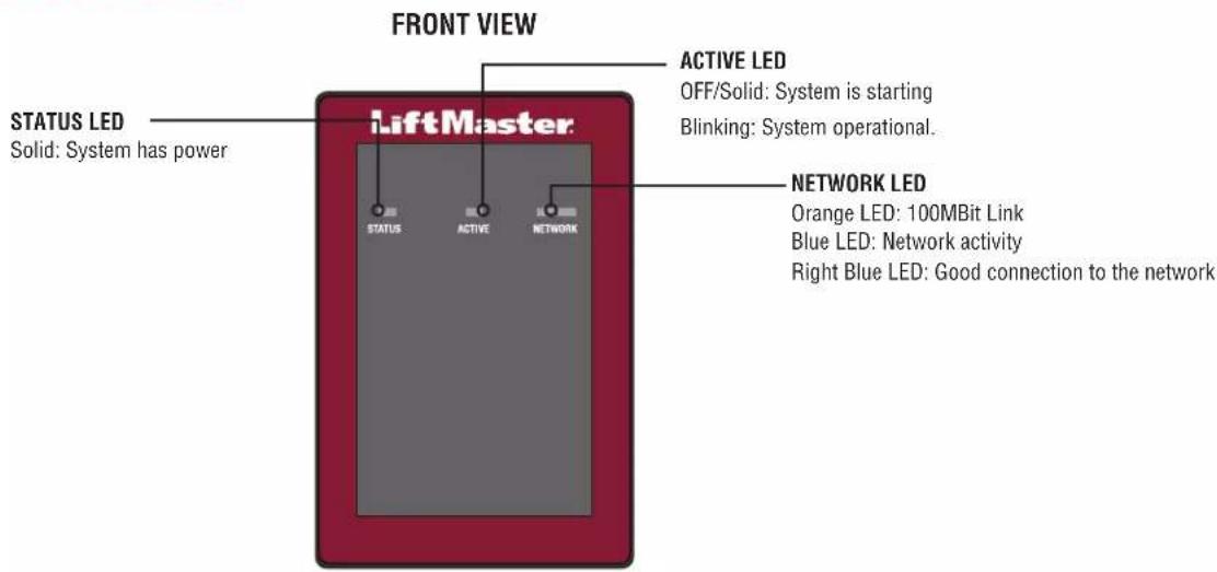
| Local Heartbeat LED indicates proper function | |
| Relay Indicator LED lights when relay is engaged (one per relay) | |
| Power Configuration Jumper selects between PoE or Wired Power Supply | |
*NOTE: Compliance to IEEE 802.3, at or af, was not evaluated by UL.
Carton Inventory
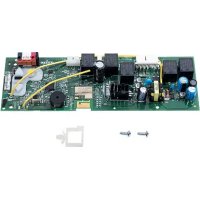
- Door Controller
USB Cable
Diodes - Installation Manual
Tools Needed
PH2 Phillips Screwdriver
- Precision 1/8" Flat or PHO Phillips Screwdriver
1/4" Nut Driver
Drill/Driver
7/64" Drill Bit
- Hammer Drill Bits for Drill/Driver
RJ45 Crimping Pliers
Multimeter
- Measuring tape
Conduit Bender
Conduit Cutter/Reamer
- Hack Saw
Center Punch Tool
Hammer
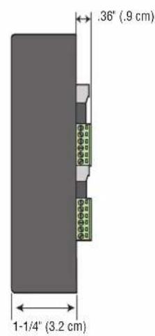
Dimensions
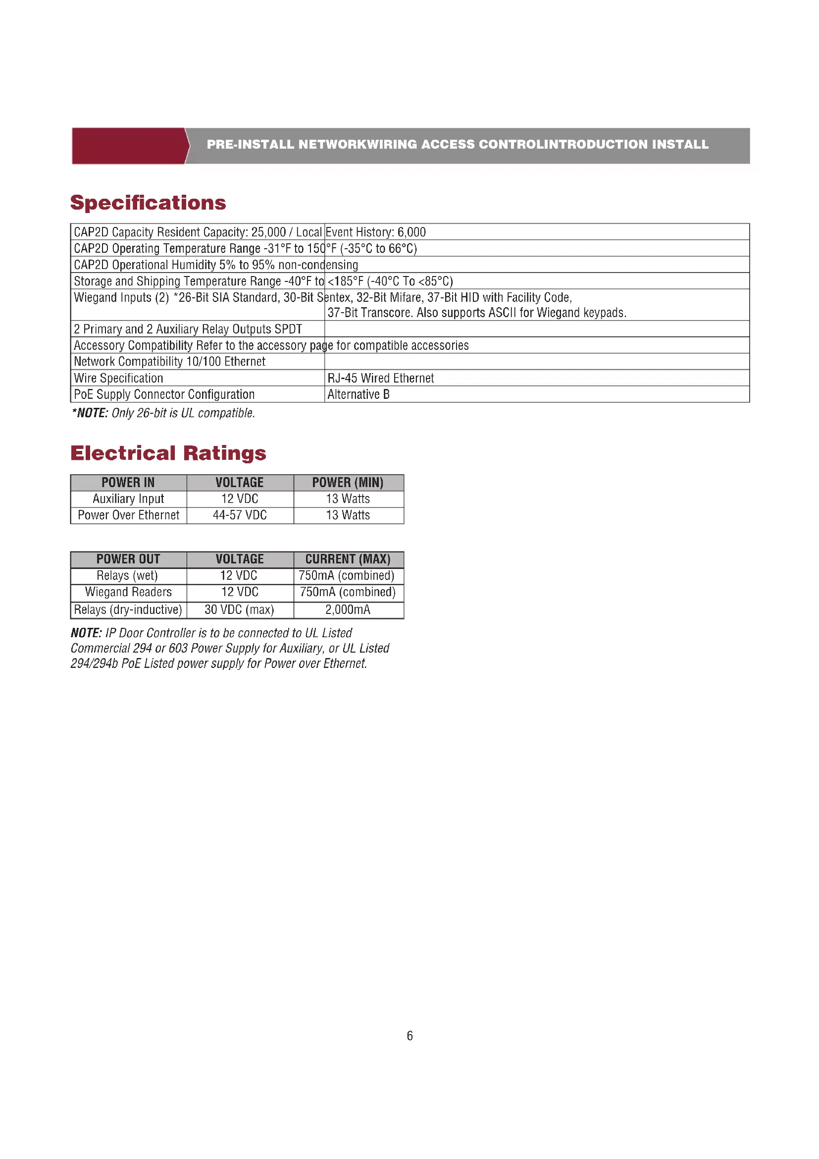
Specifications
| CAP2D Capacity Resident Capacity: 25,000 / Local | Event History: 6,000 |
| CAP2D Operating Temperature Range -31°F to 150°F (-35°C to 66°C) | |
| CAP2D Operational Humidity 5% to 95% non-condensing | |
| Storage and Shipping Temperature Range -40°F to <185°F (-40°C To <85°C) | |
| Wiegand Inputs (2) *26-Bit SIA Standard, 30-Bit S | sentex, 32-Bit Mifare, 37-Bit HID with Facility Code, 37-Bit Transcore. Also supports ASCII for Wiegand keypads. |
| 2 Primary and 2 Auxiliary Relay Outputs SPDT | |
| Accessory Compatibility Refer to the accessory page for compatible accessories | |
| Network Compatibility 10/100 Ethernet | |
| Wire Specification | RJ-45 Wired Ethernet |
| PoE Supply Connector Configuration | Alternative B |
*NOTE: Only 26-bit is UL compatible.
Electrical Ratings
| POWER IN | VOLTAGE | POWER (MIN) |
| Auxiliary Input | 12 VDC | 13 Watts |
| Power Over Ethernet | 44-57 VDC | 13 Watts |
| POWER OUT | VOLTAGE | CURRENT (MAX) |
| Relays (wet) | 12 VDC | 750mA (combined) |
| Wiegand Readers | 12 VDC | 750mA (combined) |
| Relays (dry-inductive) | 30 VDC (max) | 2,000mA |
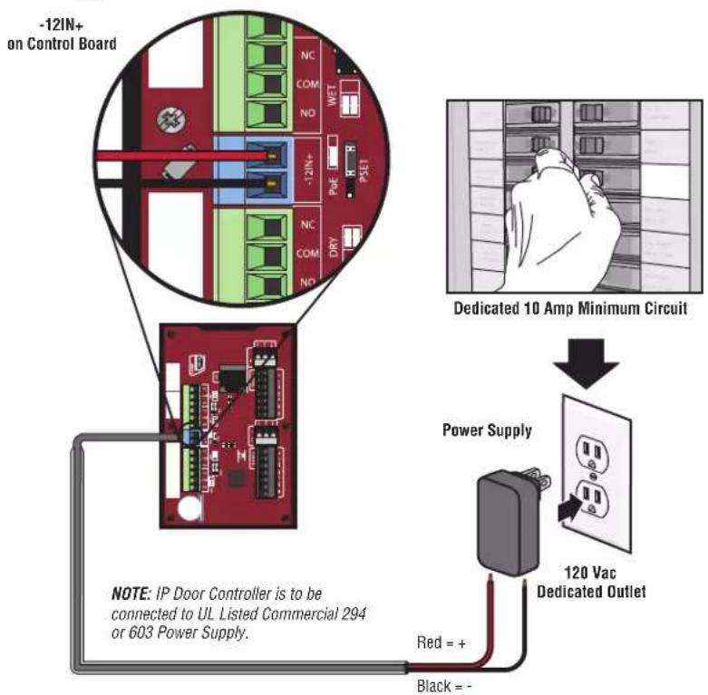
NOTE: IP Door Controller is to be connected to UL Listed Commercial 294 or 603 Power Supply for Auxiliary, or UL Listed 294/294b PoE Listed power supply for Power over Ethernet.
Wire Specifications
Use this chart to pull wires in preparation of your installation.
| DESCRIPTION OF WIRE RUN WIRE SPECIFICATION MAXIMUM RUN DISTANCE | ||
| Power Wire, secondary DC output 2-Conductor 1 | 4 AWG | Up to 60 feet (18.3 m) |
| 2-Conductor 16 AWG | Up to 37 feet (11.3 m) | |
| 2-Conductor 18 AWG | Up to 24 feet (7.3 m) | |
| Local Area Network (LAN) | 8-Conductor, 24 AWG Twisted pair 328 feet* (100 m) | |
| CAT 5/6 Network Cable | ||
| Door Strike/LiftMaster Gate Operator 2-Conductor | 18-22 AWG Shielded 100 - 250 feet (30.5 - 76.2 m) | |
| Magnetic Lock 2-Conductor 18-22 AWG 50 - 125 | feet (15.2 - 38.1 m) | |
| Dry Contact Closure (Most Gate Operators) 2-Conductor | 18-22 AWG Shielded 500 - 2500 feet (152.4 - 762 m) | |
| Exit Request (REX) 2-Conductor 18-22 AWG 500 feet (152.4 m) | ||
| Supervised Input 2-Conductor 18-22 AWG 500 feet (152.4 m) | ||
| Wiegand/Proximity Readers 7-Conductor 18-22 AWG Shielded 500 feet (152.4 m) | ||
NOTE: Main power supply and control wiring MUST be run in separate conduits. Conduits must be UL approved for low and high voltage. Refer to the NEC, ANSI/NFPA 70 for additional wiring requirements.
NOTE: Place the CAP2D unit within 500 feet of its associated electronic strike or latch. Monitoring Software is not UL evaluated.
Always provide power from a dedicated source. Plug provided transformer into an outlet wired to its own 10 Amp minimum circuit breaker. This will prevent two problems:
- Other equipment cannot introduce spikes, noise, surges or dips into the power circuit that will affect the system.
- The system's operation will not be affected if any other equipment develops a short circuit across the power line.
* CAT 5/6 NETWORK CABLE NOTES:
- For outdoor distances exceeding 140 feet (42.7 m), a UL497 compliant primary surge protector MUST be installed at the controller.
- Distances exceeding 328 feet (100 m) can be accommodated with additional hardware. Contact Technical Support for more information. Additional hardware was not evaluated under UL294.

Internet Service
The controller MUST be configured with the proper network settings to operate.
NETWORK
Internet service provider:
Automatic IP addressing: DHCP (default setting)
OR
Static IP Addressing: Optional, requires connection to PC with USB (NOTE: Write down the following for future reference: IP, Netmask, Gateway, Primary, Secondary, Server Port)

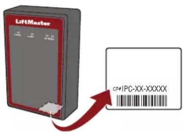
CP# for Controller
(Located on a label on the housing)
IPC

Setup a myQ® Business™ Account
NOTE: If you have an existing myQ account, your myQ BusinessTM account will have the same password.
- If you do not have a myQ® Business™ Account, call LiftMaster Customer Care and myQ business account creation at 877-247-6764 to activate a myQ® Business™ Service account.
- You will get a welcome email from LiftMaster. Accept the email invitation and register or login to your account.
- Set up the Facility and add residents and credentials (refer to the available Help in myQ BusinessTM).
- Continue with the installation of the CAP2D in this manual.
myQ
business
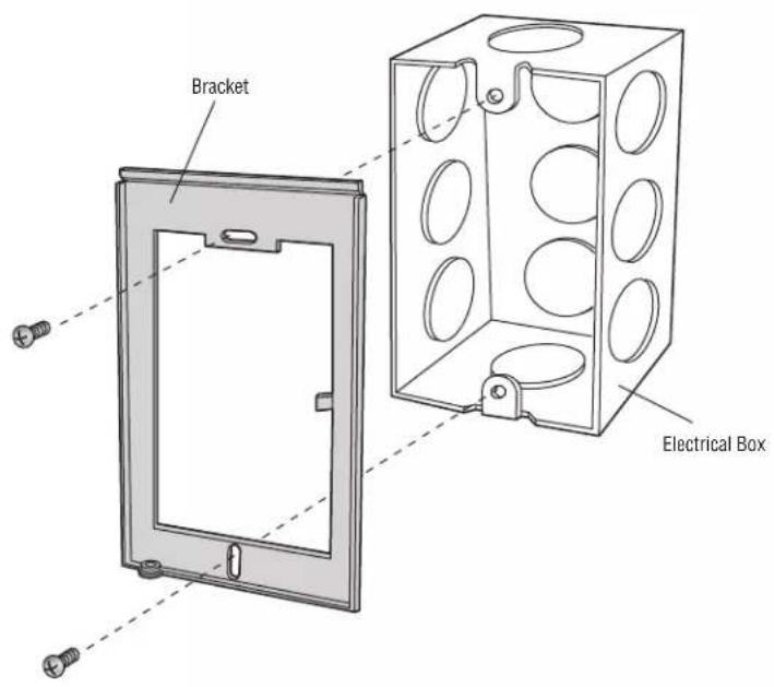
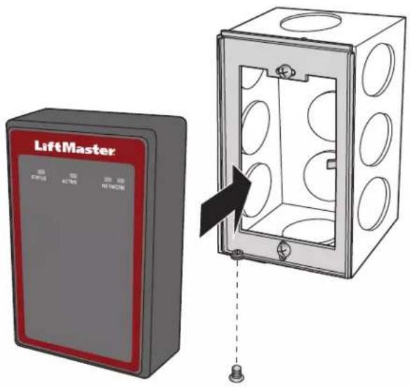
4 Mount the Bracket
- Install an electrical box in the desired mounting location.
NOTE: Use 4^ square electrical box (minimum of 1 1/2 deep) with a single-gang plaster ring. Use Wiremold® V5744S or BW35 for surface-mount installations. - Remove the bracket from the back of the CAP2D.
- Mount the bracket to the electrical box.
- Run all wiring to the electrical box.
- Once all the wiring is completed, position the CAP2D in the bracket and secure it at the bottom with the provided screw.

Connect Power
USING PoE (POWER OVER ETHERNET):
- Connect Ethernet cable to the LAN/PoE connection on the control board.
- Move PoE jumper to Power over Ethernet (PoE) setting.
USING A DC POWER SUPPLY:
The outlet for the controller MUST be an external dedicated 120 Vac outlet located within 60 feet (18.3 m) cable run of the controller. This outlet is recommended to be wired back to its own 10 Amp minimum circuit breaker.
| WIRE SPECIFICATION MAXIMUM RUN DISTANCE |
| 14 AWG Up to 60 Feet (18.3 m) |
| 16 AWG Up to 37 Feet (11.3 m) |
| 18 AWG Up to 24 Feet (7.3 m) |
- Connect 14-18 AWG wire to the stripped secondary DC output wires on the power supply. Black is negative and red is positive.
- Connect the power supply wires to the +12IN- terminal block (red to + and black to -).
- Plug the power supply into a 120 Vac outlet after all connections have been made.

WARNING
DO NOT connect a DC power supply if Power Over Ethernet (PoE) is selected and connected. Board may be damaged and is NOT covered under the warranty

CAUTION
DO NOT power electronic strikes and latches with the same power supply used to power the access control panel; doing so will cause DAMAGE to the controller. Use ONLY a UL listed burglar alarm or access control system to power electronic strikes and latches.
DO NOT connect the power supply to a switched outlet or otherwise controlled AC outlet.
DO NOT connect the power supply to the 120 Vac outlet until ALL wiring is completed.
- Install the transient noise suppression device (MOV) supplied with the controller for AC powered devices and Diode for DC powered devices.
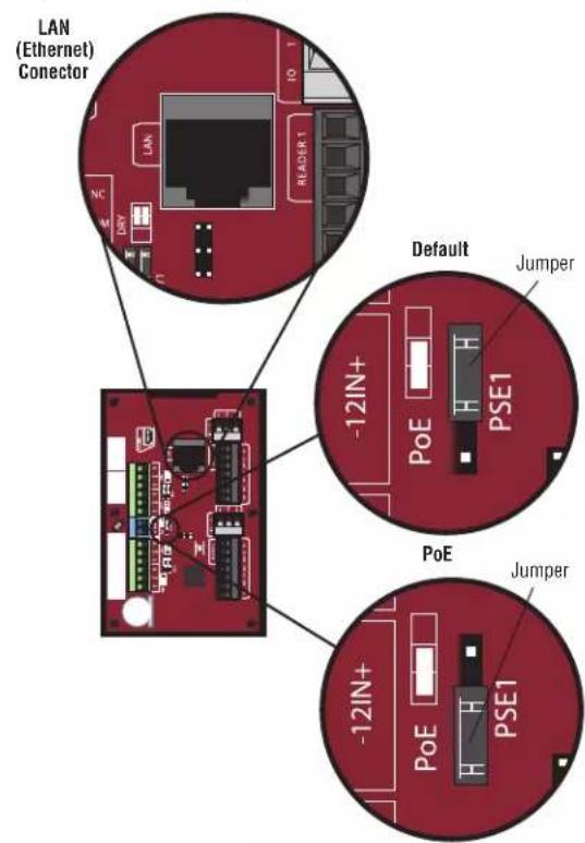
PoE (Power Over Ethernet)
Power Supply
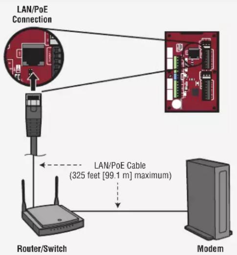
1 Connect Internet
The Local Area Network (LAN) port is a 10/100 Ethernet interface with an RJ45 jack for connecting the CAP2D to a hub, switch, or router in order to gain connectivity to the Internet. Use a straight, (i.e., non-crossover) Cat5, Cat5e, or Cat6 cable to connect to a local hub, switch or router. This type of cable is referred to as an Ethernet cable in this manual.
- Connect an Ethernet cable from the hub, switch, or router to the LAN port on the Control Board. When connected properly, the Router, Switch, or Hub Ethernet Green or Amber LED will light/flicker. If the LED light is not lit, check the connections on the controller and the Ethernet hub.
- The default connection is DHCP, no additional configuration is required. If a fixed IP address is required for your setup, use the USB cable provided to connect the controller to a PC.
Static IP (Optional)
LiftMaster recommends the CAP2D be used in Dynamic IP (DHCP) mode, but it can be set to Static IP if required.
Note: Requires Windows Vista and newer.
- Connect the CAP2D to your laptop using the included USB connector. Connect power to the CAP2D using either a router/switch capable of providing Power Over Ethernet (POE) or the included power supply. If using the included power supply, move the POE jumper.
- Install USB drivers
a. Navigate to "Computer"
b. Right click on "LiftMaster CAP2D Resources"
c. Click on the "Driver" folder
d. Click on the "LiftMasterCAP2DDriverSupport"
e. Allow the setup program to use administrative privileges
f. Click "Next"
d. Accept any warning dialogs
h. Click Finish
i. After Installation, a message will display asking you to reboot the PC. You may select "Reboot Later".
j. Remove the USB Cable from the PC and wait for the PC to acknowledge removal.
- Set static IP address:
a. Next Reinsert the USB cable into the PC and wait for the PC to acknowledge the device.
b. Open your browser and enter the address http://192.168.207.1 to access the Administrator Interface.
c. The login page displays:
d. The login is "cli".
e. The password is "new5cli".
f. Click on the Networking tab.
g. Click IP Configuration.
h. Click the "Deactivate DHCP" button.
i. Fill in the fields according to the IT staff.
j. Click Set Static Parameters. Changes have been saved.
- How to return to DHCP Configuration
a. Open your browser and enter the address http://192.168.207.1
b. The login page displays:
c. The login is "cl"
d. The password is "new5cli".
e. Click Networking tab.
f. Click IP Address Configuration. Click the "Activate DHCP" button.
- To verify connectivity:
a. Open myQ BusinessTM
b. Add the CAP2D to a facility and confirm status is "Online"
Admin Mode
- Connect a laptop to the CAP2D ADMIN USB port on the unit using a standard USB Mini-B cable.
a. The CAP2D ADMIN port is a USB interface for connecting the CAP2D unit to a laptop or PC to gain access to the local administrative interface for debug and manual configuration utilities.
b. The port requires a USB Mini-B cable for access between the laptop and the CAP2D unit.
Wiring REX (Request-to-Exit) and Doors/LiftMaster Gate Operators
- Wire the REX and DOOR terminal block.
a. Connect the Normally Open (NO) contacts of the REX device to the REX and COM terminals. Enable Request to Exit settings in myQbusiness.com Door settings tab. Select State [x] NO (Normally Open).
- When the switch closes, it initiates a Request-to-Exit (REX) program sequence, including the option to activate the door or other relays, fire and door strike, and suppress any "Door Forced" messages.
b. Connect the Normally Closed (NC) contacts of the Door Sensor to the COM and CONTACT terminals. Enable Request to Exit settings in myQbusiness.com Door settings tab. Select State [x] NC (Normally Closed).
-
In this context, an NC switch is considered closed when the door is closed (magnet present), and open when the door is open (no magnet is present).
-
When the switch is open, the control panel interprets this input as a "Door Open" condition. When the switch is closed, the control panel interprets this input as a "Door Closed" condition.
-
This circuit provides door status information (open/closed) to the control panel so myQ® Business™ can take appropriate action locally, or send email notifications if necessary.
-
Wire the DOOR LOCK RELAY terminal block.
a. Connect the door latch to the COM terminal and either the NO or NC terminal.
b. The DOOR LOCK RELAY provides both NO (Normally Open) and NC (Normally Closed) contacts, and is driven in response to the presentation of valid credentials or the programmable REX input.
c. Timing and other aspects of relay activation are programmed through myQ BusinessTM.
3. If used for an alarm shunt, wire the AUX RELAY 1 terminal block. If not used for an alarm shunt, AUX RELAY 1 can be used for a variety of purposes. Enable [x] Use Aux Relay setting in myQbusiness.com Door settings tab.
4. Wire AUX RELAY 2. Like the AUX RELAY 1, this terminal block can be used for a variety of purposes. Enable [x] Use Aux Relay setting in myQbusiness.com Door settings tab.
NOTE: The fully programmable AUX RELAYs provide both NO (Normally Open) and NC (Normally Closed) contacts.
WARNING
There is a 3 AMP 24 Volt DC limit on through current for ALL relays.
Wiring REX and Doors/LiftMaster Gate Operators (continued)
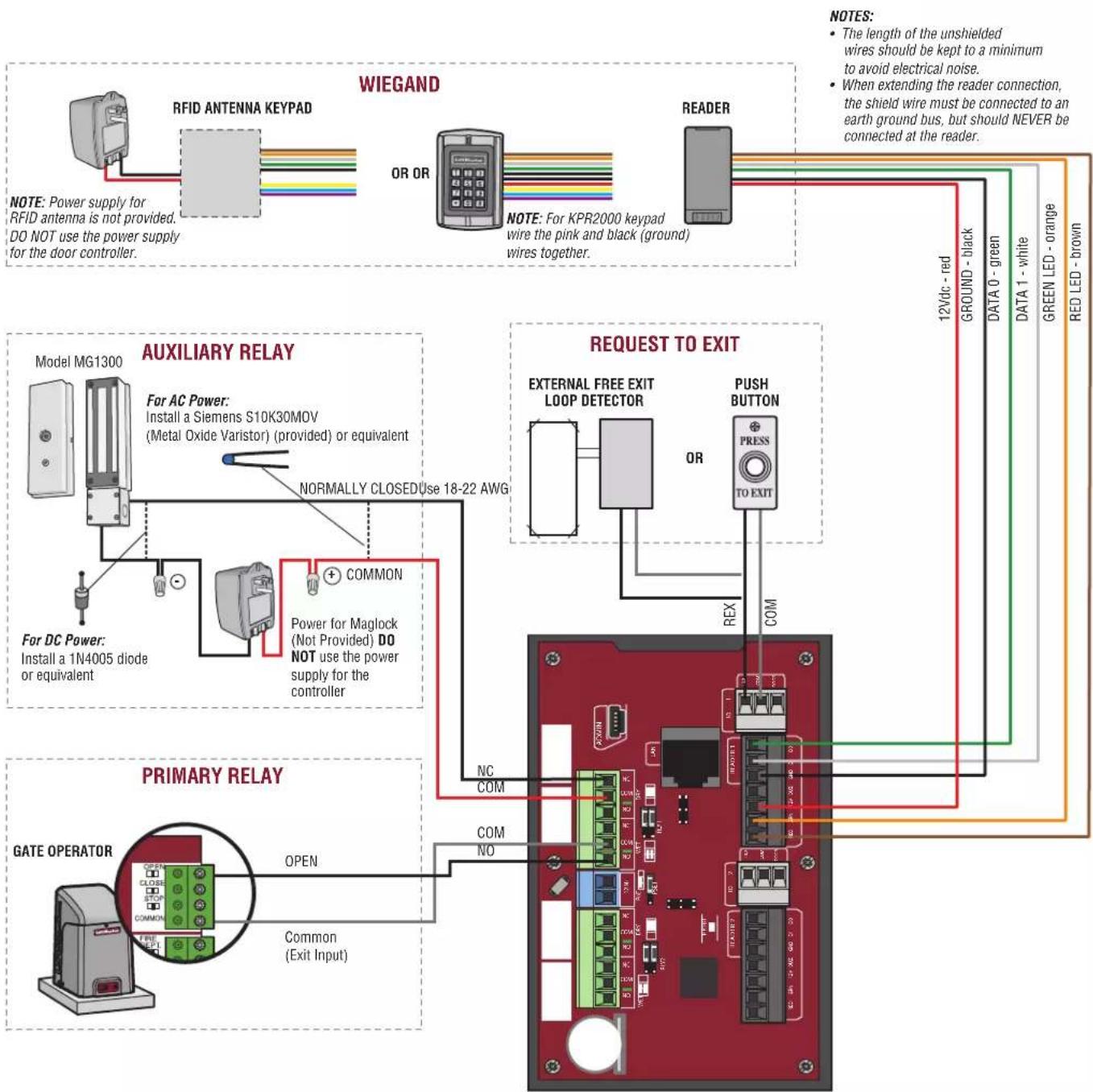
- Wire the Reader to the Wiegand Input of terminals in this door node.
NOTE: Refer to the Wiring Guide provided with the Reader/Keypad for connection diagrams.
a. Use the wire recommended by the manufacturer of the reader or keypad. If no wire is recommended, use a minimum of 22 AWG wire with sufficient conductors that include shield (drain).
b. The reader interface uses standard Wiegand wiring conventions. Connect the wire properly to the terminal block on the appropriate board node. Following is a typical, but not universal, wiring guide. Refer to the Wiring Guide provided with the Reader/Keypad for guidelines related to your specific reader or keypad
- Connect the green reader wire to the DATA0 terminal. This is the standard Data 0 circuit for Wiegand readers.
- Connect the white reader wire to the DATA1 terminal. This is the standard Data 1 circuit for Wiegand readers.
- Connect the black reader wire to the GND terminal. This is the standard Ground circuit for the reader.
- Connect the blue reader wire to the BUZZ terminal. This is the standard Buzzer circuit for the reader.
- Connect the red reader wire to the 12VDC terminal. This provides +12VDC to power the reader.
- Connect the orange reader wire to the GRN LED terminal. This is the green LED circuit.
-
Connect the brown reader wire to the RED LED terminal. This is the red LED circuit
-
Install MOVs.
a. Install the MOV across the NC and Common terminals, as close as possible to the electric strike or latch. This will normally be at the connection from the field-installed wiring to the pigtail or screw terminals of the electronic strike or latch.
b. Use the wire recommended by the manufacturer of the electric strike or latch. If no wire is recommended, use a minimum of 18 AWG wire with sufficient strands for the specific electronic strike or latch.
WARNING
Install the transient noise suppression device (mov) supplied with the control panel.
Operation
Normal Standby Operation: The CAP2D is always in ready state and is monitoring its inputs for changes. If any of the inputs change state, the CAP2D responds locally and communicates the change to myQ® Business™.
Reader/Keypad Operation: The CAP2D is designed to work with an approved reader and keypad using standard 26 bit Wiegand format. Some keyboards may use ASCII format to pass Entry Codes.
Refer to the wiring diagram for physical connection to the CAP2D. Refer to the reader and keypad manual for full operating instructions.
Access Granted/Access Denied: When a valid credential is presented, access is granted with no audio or visual feedback from the CAP2D. Some accessory devices may provide feedback. E.g., a card reader or receiver may beep or change colors of an LED to convey the status.
Maintenance and Testing: No periodic maintenance or testing is required for the product to maintain safe normal operation.
Gate Access
Disconnect power BEFORE making electrical connections. Below is an example of a wiring setup for gate access. Gate access can be wired to Door 1 or 2.
NOTE: Power Supplies shall be UL Listed Commercial 294 or 603 power limited output Power Supplies.
Door Access
Disconnect power BEFORE making electrical connections. Below is an example of a wiring setup for door access. Door access can be wired to Door 1 or 2.
NOTE: Power Supplies shall be UL Listed Commercial 294 or 603 power limited output Power Supplies.
NOTES:
The length of the unshielded wires should be kept to a minimum to avoid electrical noise.
- When extending the reader connection, the shield wire must be connected to an earth ground bus, but should NEVER be connected at the reader.


Install the CAP2D
- Make sure all the wiring is tucked into the electrical box.
- Slide the CAP2D onto the bracket and secure with the screw.
NOTE: The control units shall be mounted in a protected area. The exit device REX and wiring must be contained within the secured area.
Validate Proper Operation: Test each credential type and ensure proper behavior of each gate/door connected to CAP2D. Valid credentials and Request to Exit inputs should trigger the relay. Go to myqbusiness.com for programming and to check CAP2D activity and status.
Accessories
| ITEM PART NUMBER | |
| Waterproof Keypad/Proximity Reader KPR2000 | |
| UHF Long Range RFID Reader LMSC1000 |
Troubleshooting
CAP2D does not power on after connecting 12VDC transformer.
Check position of PoE jumper. Move jumper to the top position.
Relay does not trigger when a credential is presented.
Check power; are LEDs powered on? Check input devices and connections for proper operation. Check myQ® Business™ activity log to aid in diagnosing.
I received an email saying the CAP2D was offline.
Check myQ® Business™ for latest online/offline status. If still offline check local Internet connection and power to the CAP2D. Sometimes this is also triggered during regular maintenance on the myQ® Business™ Servers. CAP2D stores the database locally and continues to provide access control without an Internet connection. Activity and database changes are only exchanged with myQ® Business™ when CAP2D is online.
Support Contacts
| CGI - PROFESSIONAL ACCESSIBILITY | |
| Web LiftMaster.com | |
| FAQs Support Partner. LiftMaster.com/s/ | |
| Dealer Installation & myQ® Business™ Support Videos YouTube.com/LiftmasterSupport | |
| Commercial/Professional Support: (877) 247-6764 Mon-Fri 5:00 a.m. to 6:00 p.m. MST | |
| LiftMaster Training Academy LiftMasterTraining.com | |
| Partner Portal Partner. LiftMaster.com/login |

business
For myQ® Business™ programming please visit www.myqbusiness.com
Configuration Sheet
Record device information and configuration settings below.
| Controller Name: NOTE: Any user of the system is subject to the terms outlined in the product EULA. |
| Notes: |
DEVICE CONFIGURATION:
| DOOR 1 | DOOR/GATE NAME: | |||
| INPUTS | WIEGAND REX STATUS | |||
| EOL (Y/N) | ||||
| OUTPUTS | PRIMARY RELAY AUXILIARY RELAY | |||
| N.O. N.C. N.O. N. C. | ||||
| Notes: | ||||
| DOOR 2 | DOOR/GATE NAME: | |||
| INPUTS | WIEGAND REX STATUS | |||
| EOL (Y/N) | ||||
| OUTPUTS | PRIMARY RELAY AUXILIARY RELAY | |||
| N.O. N.C. N.O. N.C. | ||||
| Notes: | ||||
Legal Disclaimers
Federal Communications Commission (FCC) Compliancy
This equipment has been tested and found to comply with the limits for a Class B digital device, pursuant to Part 15 of the FCC Rules. These limits are designed to provide reasonable protection against harmful interference in a residential installation or when the equipment is operated in a commercial environment. This equipment generates, uses and can radiate radio frequency energy and, if not installed and used in accordance with the instruction manual, may cause harmful interference to radio communications. However, there is no guarantee that interference will not occur in a particular installation. If this equipment does cause harmful interference to radio or television reception, which can be determined by turning the equipment off and on, the user is encouraged to try to correct the interference by one or more of the following measures:
- Increase the distance between the equipment and receiver.
- Connect the equipment to a circuit other than the one to which the receiver is connected.
- Consult the dealer for help.
Canada-Underwriters Laboratories (C-UL) Compliancy
For C-UL Listed applications, the controller shall be installed in accordance with Part 1 of the Canadian Electrical Code.
Documentation Disclaimer and Restrictions
Information in this document is subject to change without notice and does not represent a commitment on the part of LiftMaster. For the most up-to-date information, visit www.LiftMaster.com.
This document and the data herein shall not be duplicated, used or disclosed to others for procurement or manufacturing, except as authorized with the written permission of LiftMaster. The information contained within this document or within the product itself is considered the exclusive property of LiftMaster. All information in this document or within the hardware and software product themselves is protected by the copyright and/or other intellectual property laws of the United States.
UL 294 Access Control Unit Level 1 (Attack, Line Security, Standby), and Level IV Endurance
NOTICE: To comply with FCC and/or Industry Canada (IC) rules, adjustment or modifications of this digital device are prohibited. THERE ARE NO USER SERVICEABLE PARTS. Any changes or modifications not expressly approved by the party responsible for compliance could void the user's authority to operate the equipment.
This device complies with Part 15 of the FCF rules and IC License-Exempt RSS Standard(s). Operation is subject to the following two conditions: (1) this device may not cause harmful interference, and (2) this device must accept any interference received, including interference that may cause undesired operation.
This Class B digital apparatus complies with Canadian ICES-003.
This device has been tested and found to comply with the limits for a Class B digital device, pursuant to part 15 of the FCC rules. These limits are designed to provide reasonable protection against harmful interference in a residential installation. This equipment generates, uses and can radiate radio frequency energy and, if not installed and used in accordance with the instructions, may cause harmful interference to radio communications. However, there is no guarantee that interference will not occur in a particular installation. If this equipment does cause harmful interference to radio or television reception, which can be determined by turning the equipment off and on, the user is encouraged to try to correct the interference by one or more of the following measures:
Reorient or relocate the receiving antenna.
- Increase the separation between the equipment and receiver.
- Connect the equipment into an outlet on a circuit different from that to which the receiver is connected.
- Consult the dealer or an experienced radio/TV technician for help.
- This device must be installed in a way where a minimum 8^ (20 cm) distance is maintained between users/bystanders and device.
Warranty
LiftMaster ("Seller") warrants to the first purchaser of this product, for the structure in which this product is originally installed, that it is free from defect in materials and/or workmanship for a period of two years from the date of purchase.
The proper operation of this product is dependent on your compliance with the instructions regarding installation, operation, maintenance and testing. Failure to comply strictly with those instructions will void this limited warranty in its entirety.
If, during the limited warranty period, this product appears to contain a defect covered by this limited warranty, call 1-877-247-6764 before dismantling this product. Then send this product, pre-paid and insured, to our service center for warranty replacement. Products returned to Seller for warranty replacement, which upon receipt by Seller are confirmed to be defective and covered by this limited warranty, will be replaced (at Seller's sole option) at no cost to you and returned pre-paid. Defective parts will be replaced with new or factory-rebuilt parts at Seller's sole option.
THIS LIMITED WARRANTY IS IN LIEU OF ANY OTHER WARRANTYES, EXPRESS OR IMplied, INCLUDING ANY IMPLIED WARRANTY OF MERCHANTABILITY OR FITNESS FOR A PARTICULAR PURPOSE OR OTHERWISE, AND OF ANY OTHER OBLIGATIONS OR LIABILITY ON SELLER'S PART. THIS LIMITED WARRANTY DOES NOT COVER NON-DEFECT DAMAGE, DAMAGE CAUSED BY IMPROPER INSTALLATION, OPERATION OR CARE (INCLUDING, BUT NOT LIMITED TO ABUSE, MISUSE, FAILURE TO PROVIDE REASONABLE AND NECESSARY MAINTENANCE, UNAUTHORIZED REPAIRS OR ANY ALTERATIONS TO THIS PRODUCT), LABOR CHARGES FOR REINSTALLING A REPAIRED OR REPLACED UNIT, PROBLEMS RELATED TO INTERFERENCE, OR REPLACEMENT OF BATTERIES.
UNDER NO CIRCUMSTANCES SHALL SELLER BE LIABLE FOR CONSEQUENTIAL, INCIDENTAL OR SPECIAL DAMAGES ARISING IN CONNECTION WITH USE, OR INABILITY TO USE, THIS PRODUCT. IN NO EVENT SHALL SELLER'S LIABILITY FOR BREACH OF WARRANTY, BREACH OF CONTRACT, NEGLIGENCE OR STRICT LIABILITY EXCEED THE COST OF THE PRODUCT COVERED HEREBY. NO PERSON IS AUTHORIZED TO ASSUME FOR US ANY OTHER LIABILITY IN CONNECTION WITH THE SALE OF THIS PRODUCT.
Some states do not allow the exclusion or limitation of consequential, incidental or special damages, so the above limitation or exclusion may not apply to you. This limited warranty gives you specific legal rights, and you may also have other rights which vary from state to state.
myQ® Business™
MANUEL D'INSTALLATION
Modèle CAP2D
LiftMaster®
INTRODUCTION
)