STAR1000 - Security and Access Control System LIFT-MASTER - Free user manual and instructions
Find the device manual for free STAR1000 LIFT-MASTER in PDF.
| Product Type | Single-channel commercial access control receiver |
| Brand | LiftMaster |
| Model | STAR1000 |
| System Capacity | 1,000 devices |
| Power Supply | 9-30 V AC or 9-42 V DC |
| Operating Current | 50 mA max |
| Standby Current | 30 mA max |
| Operating Temperature | -40°C to +65°C |
| Frequency | Security+ 2.0 (310, 315, 390, 433.30, 433.92, 434.54, 868.30, 868.95, 869.85 MHz) |
| Display Type | LCD 22 characters x 5 lines |
| Protection Rating | IPX44 (weatherproof) |
| Relay Contact Rating | 1 A at 24 V AC/DC |
| Compatibility | HomeLink, Security+ 2.0 remotes and keypads |
| Main Functions | Programming, deletion, stop, inquiry, relay setting, contrast, language, beep |
| PIN Configuration | 6-digit PIN to restrict administrator access |
| Installation | Wall mount, wiring with weatherproof connector, antenna included |
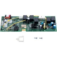
| Replacement Parts | Antenna (K76-36681), memory module (K1D7530-4), mounting bracket (K13-36651-1) |
| Compatible Accessories | Remotes 811LM, 813LM, etc.; keypads 877LM, 877MAX; antenna extensions 86LM/86LMT |
| Maintenance and Cleaning | Clean the display with a soft, dry cloth. Do not use chemicals. |
| Safety | Disconnect power before installation. Keep remotes out of reach of children. Do not use for residential garage doors without safety devices. |
| Repairability | No user-serviceable internal parts. Replacement parts available. |
Frequently Asked Questions - STAR1000 LIFT-MASTER
User questions about STAR1000 LIFT-MASTER
0 question about this device. Answer the ones you know or ask your own.
Ask a new question about this device
Download the instructions for your Security and Access Control System in PDF format for free! Find your manual STAR1000 - LIFT-MASTER and take your electronic device back in hand. On this page are published all the documents necessary for the use of your device. STAR1000 by LIFT-MASTER.
USER MANUAL STAR1000 LIFT-MASTER
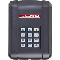
The STAR1000 is a high capacity single channel commercial access control receiver for commercial door operators, and dry contact triggered devices. The STAR1000 is compatible with Security+ 2.0™ remote controls and wireless keyless entries, Security+ 2.0™ Passport and Passport Lite remote controls. This receiver is compatible with HomeLink®. For programming or compatibility information visit www.homelink.com. The receiver capacity is 1,000 devices and can be any combination of remote controls and wireless keyless entries. The receiver is watertight according to IPX44 specification.
INSTALLATION
- Select a convenient location near the operator to be controlled by the receiver within "line of sight" of the intended transmitting location.
NOTE: Do not mount LCD screen in direct sunlight. Avoid mounting the receiver in a metal enclosure or near other wireless receiving or transmitting devices. - Mount the bracket to the desired surface with appropriate hardware (not provided) (Figure 1).
- Remove the 4 (#8) screws on the back of the receiver and remove the faceplate. Unplug the keypad connector from the control board.
NOTE: Be careful not to damage the keypad cable while removing the faceplate.
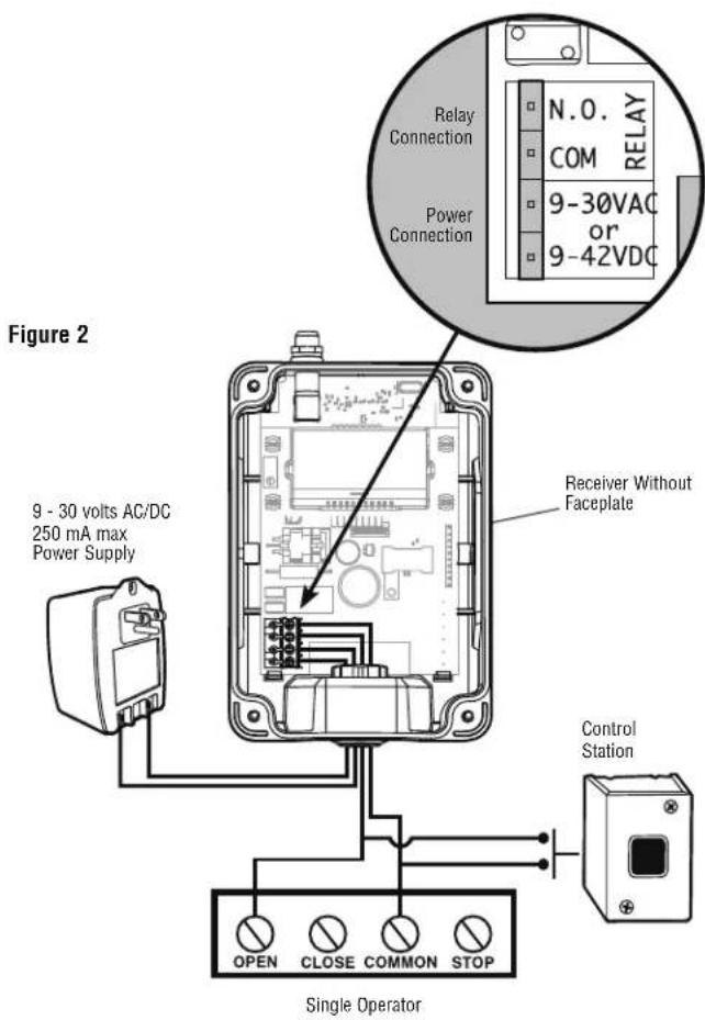
- Make wiring connections (Figure 2). Refer to your gate or commercial door operator owner's manual for more specific information.
- Reconnect the keypad connector to the board (labeled J9).
- Secure the faceplate with the 4 (#8) screws previously removed.
- Install the antenna provided.
NOTE: Use the optional 86LM or 86LMT antenna extension kit (see page 4) to mount the remote antenna as high and far from metallic objects as possible for best radio range.
-
Snap the receiver onto the mounting bracket and secure with the (#8) screws provided.
-
Tighten the watertight connector to secure and seal the wiring.
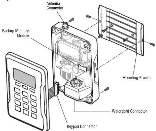
Figure 1
text_image
Antenna Connector Backup Memory Module Mounting Bracket Watertight Connector Keypad ConnectorCOMMERCIAL ACCESS CONTROL RECEIVER
MODEL STAR1000
⚠️ ⚠️ WARNING
To prevent possible SERIOUS INJURY or DEATH from electrocution:
- Be sure power is NOT connected BEFORE installing the receiver.
To prevent possible SERIOUS INJURY or DEATH from a moving gate or garage door: - ALWAYS keep remote controls out of reach of children. NEVER permit children to operate, or play with remote control transmitters.
- Activate gate or door ONLY when it can be seen clearly, is properly adjusted, and there are no obstructions to door travel.
- ALWAYS keep gate or garage door in sight until completely closed. NEVER permit anyone to cross path of moving gate or door.
WARNING
To prevent possible SERIOUS INJURY or DEATH, the use of CONSTANT OPERATION on residential openers is PROHIBITED.
When a receiver is used to activate a commercial door opener, a reversing edge MUST be installed on the bottom of the door. Failure to install a reversing edge under these circumstances may result in SERIOUS INJURY or DEATH to persons trapped beneath the door.
text_image
Figure 2 9 - 30 volts AC/DC 250 mA max Power Supply Receiver Without Faceplate Control Station OPEN CLOSE COMMON STOP Single Operator Relay Connection COM RELAY 9-30VAC or 9-42VDCUSER INTERFACE
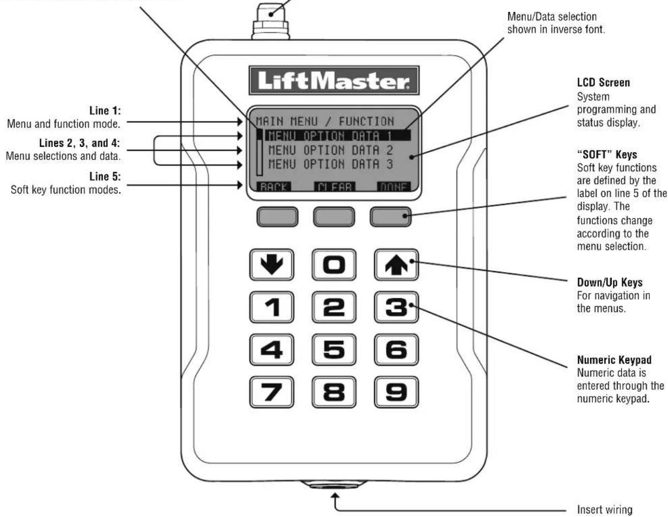
The STAR1000 user interface consists of a 22 character by 5 line LCD display, 3 "soft keys", Down/Up arrows and a numeric keypad.
Scroll Indicator
If more than 3 options exist, a scroll indicator appears on the left margin of lines 2, 3, and 4. The scroll indicator shows the relative position within the list.
Antenna Connection
For the direct antenna or the antenna extension kit.
text_image
Menu/Data selection shown in inverse font. LiftMaster. Main MENU / FUNCTION MENU OPTION DATA 1 MENU OPTION DATA 2 MENU OPTION DATA 3 BACK CLEAR DONE LCD Screen System programming and status display. Lines 1: Menu and function mode. Lines 2, 3, and 4: Menu selections and data. Line 5: Soft key function modes. "SOFT" Keys Soft key functions are defined by the label on line 5 of the display. The functions change according to the menu selection. Down/Up Keys For navigation in the menus. Numeric Keypad Numeric data is entered through the numeric keypad. Insert wiringPROGRAMMING
The receiver has the ability to learn a combination of remote control transmitters and keyless entries up to 1,000 devices. See page 4 for a complete list of compatible accessories. Audible and visual warnings occur when the receiver capacity is exceeded. After 30 seconds of inactivity, the receiver times out and the LiftMaster® logo is displayed. Select "UNLOCK" and enter the PIN to continue.
Initial PIN set up:
The PIN restricts access to authorized administrators only. If you omit this step, anyone will be able to program the receiver. Upon initial power up, the system firmware revision is displayed for 5 seconds followed by the LiftMaster® logo. When a key is pressed, "CREATE PIN?" is displayed.
-
Press "YES" to create PIN. If the PIN is lost you may request a reset code by pressing "RESET".
-
Enter a 6-digit PIN, and press "YES"; enter the 6-digit PIN a second time and press "YES" to program the PIN. If you make a mistake, press "CLEAR" to change your entry. To exit the enter PIN screen, select "BACK".
-
When your 6-digit PIN is programmed correctly, the LCD display reads "KEYPAD UNLOCKED". Select "OK" to continue to the Main Menu. After 30 seconds of inactivity, the receiver times out and the LiftMaster® logo is displayed. Select "UNLOCK" and enter PIN to continue.
PROGRAMMING COMMANDS
The table below describes the commands used to program the receiver.
MAIN MENU COMMAND DESCRIPTION
| LEARN MENU | LEARN DEVICE | Program a device to the receiver. | |
| BLOCK LEARN DEVICE | Block program a range of devices to the receiver. | ||
| LEARN TO LOC # | Program a device to a 4-digit number location. | ||
| DELETE MENU | DELETE DEVICE | Delete a specified device that has been programmed to the receiver. | |
| DELETE ALL DEVICES | Delete all programmed devices. | ||
| SUSPEND MENU | SUSPEND DEVICE | Temporarily disables the function of a specified device that has been programmed to the receiver. | |
| SUSPEND ALL DEVICES | Temporarily disables the function of ALL devices programmed to the receiver. | ||
| UNSUSPEND DEVICE | Re-enable the function of a suspended device. | ||
| UNSUSPEND ALL DEVICES | Re-enable the function of ALL suspended devices. | ||
| QUERY MENU | LOC # USED | Displays a range of used locations starting from a specified location. | |
| LOC # AVAILABLE | Displays a range of empty locations starting from a specified location. | ||
| LOC # SUSPENDED | Displays a range of suspended locations starting from a specified location. | ||
| SETTINGS | CHANGE PIN | Change the 6-digit PIN number for the receiver. | |
| DEALER INFO | Display and edit the dealer 11-digit contact phone number. | ||
| FIRMWARE VERSION | Displays the current firmware version. | ||
| BEEP | Turn the audible feedback on or off. | ||
| MEMORY DUPLICATE | MEMORY | Creates a memory backup. A backup memory module must be installed. | |
| RESTORE MEMORY | Restores a memory backup from a memory module.NOTE:Content of memory backup module will over-write any information already stored in the receiver memory. | ||
| RELAY | Sets the relay activation time from .25 to 1 second. | ||
| CONTRAST | Press Down or Up arrows to adjust LCD contrast. | ||
| LANGUAGE | Sets menu language: English (Default), Spanish, and French. | ||
| FACTORY DEFAULT | Reset receiver to factory default settings. | ||
DIAGNOSTICS
The receiver emits a series of audible beeps to signal programming and error events. The table at right lists all of the events and their audible notifications. The On/Off column indicates that the audible notification for the event may be disabled in the BEEP SETTINGS menu.
| EVENT AUDIBLE | NOTIFICATIONS | ON/OFF |
| Key press Single YES | ||
| Successful Add Double | ||
| Successful Delete Triple | ||
| Successful Suspend Double | ||
| Successful Unsuspend Double | ||
| Master PIN entry error Long | ||
| Programming error Long | ||
| Location out of range Long | ||
| Generic Success Double | ||
| Generic Error Long | ||
| Received unknown Tx Slow | YES | |
| Received known Tx Double | YES | |
| Received known suspended Tx | Long | YES |
| SPECIFICATIONS | |
| System Capacity | 1000 devices |
| Supply Voltage | 9 - 30 Volts AC, 9 - 42 Volts DC |
| Operating Current | 50 mA Maximum |
| Stand By Current | 30 mA Maximum |
| Surge Suppression | 6.0 kV Min |
| Operating Temp Range | -40°C to +65°C @ 50% Rh, -40°F to +149°F @ 50% Rh |
| Storage and Shipping Temp Range | -40°C to +85°C @ 50% Rh |
| Frequency | Security+ 2.0TM Only (310, 315, 390, 433.30, 433.92, 434.54, 868.30, 868.95, 869.85 MHz) |
| Relay Contact Rating | 1 amp @ 24V AC/DC |
| COMPATIBLE ACCESSORIES | |
| Remote Controls | 811LM, 813LM, 892LT, 894LT, 891LM, 893LM, 890/893/895MAX, PPV1, PPV3, PPK1, PPK3, PPK1PH, PPK3PH, PPLV1, PPLK1, AND PPLK1PH |
| Keypads | 877LM, and 877MAX |
| Antenna Extension Kits: | |
| 15' Extension Kits | 86LM |
| 25' Extension Kits | 86LMT |
| 24VAC Transformer for screw terminals | 95LM |
| REPAIR PARTS | |
| Antenna | K76-36681 |
| Memory Module | K1D7530-4 |
| Mounting Bracket | K13-36651-1 |
NOTICE: To comply with FCC and or Industry Canada rules (IC), adjustment or modifications of this receiver and/or transmitter are prohibited, except for changing the code setting or replacing the battery. THERE ARE NO OTHER USER SERVICEABLE PARTS.
Tested to Comply with FCC Standards for Home or office use. Operation is subject to the following two conditions: (1) this device may not cause harmful interference, and (2) this device must accept any interference received, including interference that may cause undesired operation.
FOR TECHNICAL SUPPORT DIAL OUR TOLL FREE NUMBER:
1-800-528-2806
LiftMaster®
RECEPTEUR DE CONTRÔLE D'ACCÈS COMMERCIAL
MODELE STAR1000
APPLICATION
© 2012, The Chamberlain Group, Inc.
All Rights Reserved