PPWR - Remote trigger LIFT-MASTER - Free user manual and instructions
Find the device manual for free PPWR LIFT-MASTER in PDF.

| Product Type | Remote Control Receiver with Wiegand Output (Remote Trigger) |
| Brand | LiftMaster |
| Model | PPWR |
| Power Supply | 12-24 V DC |
| Operating Current | 250 mA max |
| Standby Current | 30 mA max |
| Surge Suppression | 6.0 KV min |
| Operating Frequency | Security+ 2.0® (310, 315, 390 MHz) |
| Supported Wiegand Data Formats | 26-bit, 30-bit, 31-bit, 34-bit (even or odd), 50-bit |
| System Capacity | Up to 12,000 devices |
| Operating Temperature | -40 °C to +65 °C |
| Storage Temperature | -40 °C to +85 °C |
| Protection Rating | IP44 (Outdoor Use) |
| Operating Modes | Direct Write Mode (Default) and Advanced Mode |
| Remote Control Compatibility | Security+ 2.0® Passport MAX, Passport Lite, Passport 2.0 |
| Number of Programmable Installation Codes (Advanced Mode) | Up to 64 |
| Display | 22-character x 5-line LCD screen, numeric keypad, 3 programmable keys |
| Wiegand Output | 5 V DC, open collector |
| Maintenance and Cleaning | Clean with a soft, dry cloth. Do not use abrasive products. |
| Safety | Disconnect power before installation. Keep remotes out of reach of children. Do not operate door without visibility. Constant use prohibited for residential door openers. |
| Available Spare Parts | Straight Antenna (K76-36681), Memory Module (K1D7530-3), Mounting Bracket (K13-36651-2), Antenna Extension Kit 86LM/86LMT |
| Warranty | 1 year (Limited) |
Frequently Asked Questions - PPWR LIFT-MASTER
User questions about PPWR LIFT-MASTER
0 question about this device. Answer the ones you know or ask your own.
Ask a new question about this device
Download the instructions for your Remote trigger in PDF format for free! Find your manual PPWR - LIFT-MASTER and take your electronic device back in hand. On this page are published all the documents necessary for the use of your device. PPWR by LIFT-MASTER.
USER MANUAL PPWR LIFT-MASTER
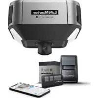
The Passport Wiegand Receiver is a Security +2.0^® receiver with a Wiegand output. The PPWR is compatible with Security +2.0^® Passport MAX and Passport Lite remote controls and access systems utilizing 26 Bit, 30 Bit, 31 Bit, 34 Bit (even or odd), and 50 Bit Wiegand code formats. The receiver has two modes of operation (see Choose a Mode, page 3):
- Pass Through Mode (Default) - passes all received remote control signals to the access system host controller.
- Advanced Mode - provides an additional layer of security in areas where other remote controls may be operating. The receiver only passes signals from a remote control with a previously programmed facility code. All other signals are blocked.
This receiver is compatible with HomeLink. Refer to instructions included with your HomeLink unit for compatibility and programming. The receiver is rated for outdoor use (IP44).
INSTALLATION
- Select a convenient location near the access system host controller within "line of sight" of the intended transmitting location.
NOTE: Do not mount the receiver in direct sunlight. Avoid mounting the receiver in a metal enclosure or near other wireless receiving or transmitting devices. If mounted in a metal enclosure, a remote antenna must be used. If using multiple receivers, maximize the distance between the two to avoid interference.
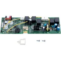
- Mount the bracket to the desired surface with appropriate hardware (not provided)(Figure 1).
- Remove the 4 #8 screws on the back of the receiver and remove the faceplate. Unplug the keypad connector from the control board.
NOTE: Be careful not to damage the keypad cable while removing the faceplate.
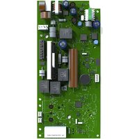
- Make wiring connections (Figure 2). Refer to your access system host owner's manual for more specific information.
- Reconnect the keypad connector to the board (labeled J9).
- Secure the faceplate with the 4 #8 screws previously removed.
- Install the antenna (provided).
WARNING
To prevent possible SERIOUS INJURY or DEATH from electrocution:
- Be sure power is NOT connected BEFORE installing the receiver. To prevent possible SERIOUS INJURY or DEATH from a moving gate or garage door:
- ALWAYS keep remote controls out of reach of children. NEVER permit children to operate, or play with remote control transmitters.
- Activate gate or door ONLY when it can be seen clearly, is properly adjusted, and there are no obstructions to door travel.
- ALWAYS keep gate or garage door in sight until completely closed.
NEVER permit anyone to cross path of moving gate or door.
WARNING
To prevent possible SERIOUS INJURY or DEATH, the use of CONSTANT OPERATION on residential openers is PROHIBITED. When a receiver is used to activate a commercial door opener, a reversing edge MUST be installed on the bottom of the door. Failure to install a reversing edge under these circumstances may result in SERIOUS INJURY or DEATH to persons trapped beneath the door.

WARNING: This product can expose you to chemicals including lead, which are known to the State of California to cause cancer or birth defects or other reproductive harm. For more information go to www.P65Warnings.ca.gov
NOTE: Use the optional 86LM or 86LMT antenna extension kit (see page 4) to mount the remote antenna as high and far from metallic objects as possible for best radio range.
- Snap receiver onto the mounting bracket and secure with the #8 screws provided.
- Tighten the watertight connector to secure and seal the wiring.
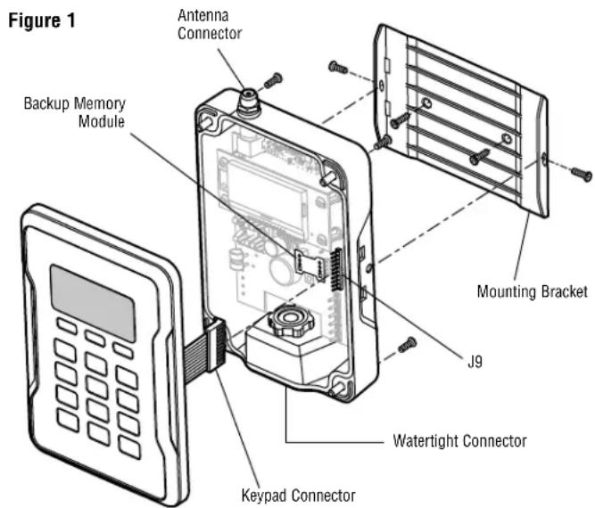
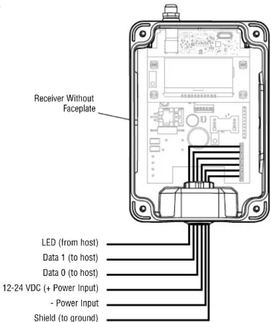
Figure 2
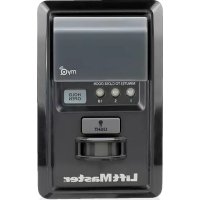
USER INTERFACE
The PPWR user interface consists of a 22 character by 5 line LCD display, 3 "soft keys", Down/Up arrows and a numeric keypad.
If more than 3 options exist, a scroll indicator appears on the left margin of lines 2, 3, and 4. The scroll indicator shows the relative position within the list.
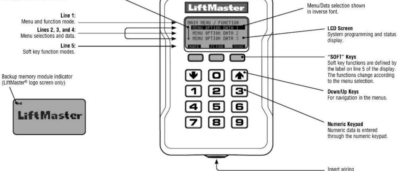
Scroll Indicator
PROGRAMMING COMMANDS
The table below describes the commands used to program the receiver.
MAIN MENU COMMAND DESCRIPTION
| WIEGAND FORMAT | 26 BIT (DEFAULT) 26 Bit Wiegand output code. | |
| 30 BIT 30 Bit Wiegand output code. | ||
| 31 BIT 31 Bit Wiegand output code. | ||
| 34 BIT EVEN 34 Bit EVEN Wiegand output code. | ||
| 34 BIT ODD 34 Bit ODD Wiegand output code. | ||
| 50 BIT 50 Bit Wiegand output code. | ||
| BUTTON FILTER | BUTTON 1 IS ON | |
| BUTTON 2 IS ON | ||
| BUTTON 3 IS ON | ||
| MODE SELECT | PASS THRU (DEFAULT) | |
| ADVANCED | ||
| SECURITY TABLE If ADVANCED MODE is turned off this option is disabled and will appear as NOT AVAILABLE FOR PASS THRU MODE | PROGRAM | |
| LIST | CHANGE FC OUT | |
| DELETE | ||
| SETTINGS | PIN Change the 6-digit PIN number for the receiver. | |
| DEALER INFO Display and edit the dealer 10-digit phone number. | ||
| FIRMWARE VERSION Displays the current firmware version. | ||
| BEEP Turn the audible feedback on or off. | ||
| MEMORY | ||
| This function creates a complete backup of programmed remote controls, and Security Table settings. The backup may be restored to a replacement PPWR or used to copy the configuration into other PPWR | ||
| Creates a memory backup. A memory module must be installed. | ||
| Restores a memory backup from a memory module. An indicator appears on the LiftMaster® logo screen if a backup memory module is installed. | ||
| NOTE: Content of memory module will over-write any information already stored in the receiver memory. Remove memory module after backing up for safe keeping. | ||
| CONTRAST | ||
| LANGUAGE Sets language: English (Default). | ||
| FACTORY DEFAULT | ||
PROGRAMMING
The PPWR receiver has the ability to learn a combination of credentialed remote control transmitters. See page 4 for a complete list of compatible accessories. After 30 seconds of inactivity, the receiver times out and the LiftMaster logo is displayed. Select "UNLOCK" and enter the master PIN to continue.
1 INITIAL PIN SET UP:
The PIN restricts access to authorized administrators only. If you omit this step, anyone will be able to program the receiver. Upon initial power up, the system firmware revision is displayed for 5 seconds followed by the LiftMaster® logo. When a key is pressed, "CREATE PIN?" is displayed.
- Press "YES" to create PIN. If the PIN is lost you may request a reset code by pressing "RESET" and calling your LiftMaster dealer.
- Enter a 6-digit PIN, and press "YES"; enter the 6-digit PIN a second time and press "YES" to program the PIN. If you make a mistake, press "CLEAR" to change your entry. To exit the enter PIN screen, select "BACK".
- When your 6-digit PIN is programmed correctly, the LCD display reads "KEYPAD UNLOCKED". Select "OK" to continue to the Main Menu. After 30 seconds of inactivity, the receiver times out and the LiftMaster logo is displayed. Select "UNLOCK" and enter PIN to continue.
2CHOSE A MODE
The receiver has two modes of operation:
Pass Through Mode (Default)
Passes all received remote control credentials to the access control system. Credential Facility Code and Identification codes are passed through without filtering or translation. No pre-configuration is necessary for normal operation. Pass through mode is most commonly used.
Advanced Mode
Advanced mode provides an additional level of security where sites may have overlapping radio coverage such as large multi-building apartment or industrial complexes. The advanced mode establishes filtered reception, only allowing Facility Codes programmed in the Security Table to pass to the access control system. Transmissions from ALL remote controls not programmed are ignored. When using Advanced Mode any new remote control Facility Codes introduced to the site must be added to the Security Table.
An additional feature of the advanced mode allows a 1 to 1 facility code translation. This feature allows installers and site managers the flexibility to program stock remote controls to the sites using a unique facility code.
NOTE: Facility code translation is limited to a 1-"FC IN" to 1-"FC OUT" or "One to One". This in effect eliminates the ability to ignore source facility code and have a single/fixed facility code output.
Use case examples:
- Building complex A entrance within 100' of Building complex B entrance. Remote controls from each is creating nuisance access denied transactions on the access controllers. Each PPWR can be set to receive only remote controls with specific facility codes.
- An apartment complex is using HID proximity credential devices programmed to facility code 22 and would like to add PPWR transmitters. The access control system only supports the use of one facility code. The PPWR advanced mode can be set to translate one source facility code "FC IN" to the desired target facility code "FC OUT". A specific remote control facility code is then translated to the desired target facility code output.
To choose Mode of operation
- Select "MODE SELECT" from the main menu. Press "OK".
- System responds with message showing current mode setting "PASS THRU SET" or "ADVANCED SET".
-
Press "EDIT".
-
Select the mode that you want to use and press "YES".
- System responds with "WARNING THIS WILL ERASE MEMORY PROCEED?". Press "YES".
- System responds with "WARNING ARE YOU SURE?" Press "YES".
- System responds with "UPDATING PLEASE WAIT". DO NOT disconnect power while updating.
- System responds with a confirmation message that the selected mode is saved.
- If you chose PASS THROUGH MODE, press "OK". No further setup is required.
- If you chose ADVANCED MODE, press "NEXT" to proceed to the SECURITY TABLE menu.
To program Security Table
The Security Table can hold up to 64 unique facility codes. If a facility code is already programmed it cannot be added again.
- Select "PROGRAM" from the Security Table menu. Press "OK"
- System responds with "PRESS BUTTON ON DEVICE OR TYPE IN MAX FC"
- Press a button on remote control or enter the FC # from the remote control's MAX FC ### (found on remote control id label) using the keypad. Press "OK"
- System responds with "MAX FC - ## SAVED". Press "OK"
To edit Security Table, or set facility code translation
- Select "LIST" from the Security Table menu. Press "OK"
- System responds with "LIST: # of 64 | MAX FC - ## | FC IN -> FC OUT | ## -> ##"
- Use "Down" and "Up" to scroll through Security Table. Press "Edit" to select an entry to edit.
- System responds with "MAX FC - ## | CHANGE FC OUT | DELETE"
- Select "CHANGE FC OUT" from the menu. Press "OK"
- System responds with "CHANGE FC OUT | ASSIGN FC OUT | AUTO SEARCH FC OUT?"
- Select "ASSIGN FC OUT" from the menu. Press "OK".
- System responds with "CHANGE FC OUT | ENTER NEW FC OUT - #"
- Enter FC number with valid range for bit format selected (example: 26 bit format, valid FC range is 1 - 255). Press "OK"
- System responds with "CHANGE FC OUT | MAX FC -## | FC OUT -## | SAVED".
- Press "OK"
- Press "HOME"
NOTE: If a different mode is selected after a site has been in operation, remote controls may initially require multiple button presses to work as the rolling code "re-syncs" to the system.
DIAGNOSTICS
The PPWR receiver was designed to emit a series of audible beeps dependent on programming and error conditions. The table below lists all of the event conditions and related audible beep notifications. Audible notifications may be disabled in the "BEEP SETTINGS" menu.
| EVENT BEEP | |
| Key press Single | |
| Successful add/change Double | |
| Successful delete Triple | |
| Master PIN entry error Long | |
| Programming error Long | |
| Generic success Double | |
| Generic error Long | |
C