Protig 201 DC FV - Welding machine GYS - Free user manual and instructions
Find the device manual for free Protig 201 DC FV GYS in PDF.

User questions about Protig 201 DC FV GYS
0 question about this device. Answer the ones you know or ask your own.
Ask a new question about this device
Download the instructions for your Welding machine in PDF format for free! Find your manual Protig 201 DC FV - GYS and take your electronic device back in hand. On this page are published all the documents necessary for the use of your device. Protig 201 DC FV by GYS.
USER MANUAL Protig 201 DC FV GYS
FR 02/03-18/115-120
EN 02/19-34/115-120
DE 02/35-50/115-120
ES 02/51-66/115-120
RU 02/67-82/115-120
NL 02/83-98/115-120
IT 02/99-114/115-120
PROTIG 201 DC FV
TIG (GTAW) and MMA (SMAW) welding machine
Cbapouhny annapat TnMMA
TIG en MMA lasapparaat
INSTALLATION - FONCTIONNEMENT PRODUIT
INTERFACE HOMME-MACHINE (IHM) (FIG-2)
CONDITIONS DE GARANTIE
Read and understand the following safety instructions before use.
Any modification or updates that are not specified in the instruction's manual should not be undertaken.
The manufacturer is not liable for any injury or damage caused due to non-compliance with the instructions featured in this manual. If there is any issue or if you are unsure, please ask a qualified person to handle the installation.
ENVIRONMENT
This equipment must only be used for welding operations in accordance with the limits indicated on the descriptive panel and/or in the user manual. Safety instructions must be followed. In case of improper or unsafe use, the manufacturer cannot be held liable.
This equipment must be used and stored in a room free from dust, acid, flammable gas or any other corrosive agent. The same rules apply for storage. Operate the machine in an open, well-ventilated area.
Temperature range:
Use between -10 and +40^ (+14 and +104^)
Storage between -20 and +55^ (-4 and 131^
Air humidity:
Lower or equal to 50% at 40^ (104^)
Lower or equal to 90% at 20^ (68^)
Altitude:
Up to 1000 meters above sea level (3280 feet).
INDIVIDUAL PROTECTION & OTHERS
Arc welding can be dangerous and can cause serious injury or even death.
Welding exposes the user to dangerous heat, arc rays, electromagnetic fields, risk of electric shock, noise and gas fumes. People wearing pacemakers are advised to consult a doctor before using the welding machine.
To protect oneself as well as others, ensure the following safety precautions are taken:

In order to protect you from burns and radiations, wear clothing without turn-up or cuffs. These clothes must be insulating, dry, fireproof, in good condition and cover the whole body.

Wear protective gloves which guarantee electrical and thermal insulation.

Use sufficient welding protective gear for the whole body: hood, gloves, jacket, trousers... (varies depending on the application/ operation). Protect the eyes during cleaning operations. Contact lenses are prohibited during use.
It may be necessary to install fireproof welding curtains to protect the area against arc rays, weld spatter and sparks. Inform the people around the working area to never look at the arc nor the molten metal, and to wear protective clothes.

Ensure ear protection is worn by the operator if the work exceeds the authorised noise limit (the same applies to any person in the welding area).
Keep hands, hair and clothes away from moving parts such as fans, and engines.
Never remove the safety covers from the cooling unit when the machine is plugged in. The manufacturer is not liable for any injury or damage due to non-compliance with the safety precautions.
Parts that have just been welded will be hot and may cause burns when touched. During maintenance work on the torch or the electrode holder, you should make sure that temperature is cold enough and wait at least 10 minutes before any intervention. When using a water-cooled torch, make sure that the cooling unit is switched on to avoid any burns that could potentially be caused by the liquid.
It is important to secure the working area before leaving it to ensure protection of the goods and the safety of people.
WELDING FUMES AND GAS

Fumes, gas and dust produced during welding are hazardous to health. It is mandatory to ensure adequate ventilation and/ or extraction to keep fumes and gas away from the work area. Using an air fed welding helmet is recommended in case of insufficient ventilation in the workplace.
Check that the air supply is suitable by referring to the recommended safety regulations.
Precautions must be taken when welding in small areas, and the operator will need supervision from a safe distance. Welding specific pieces of metal containing lead, cadmium, zinc, mercury or beryllium can be extremely toxic. The user will also need to remove the grease from the workpiece before welding.
Gas cylinders must be stored in an open or ventilated area. They must be stored vertically and held by a support or trolley to limit the risk of fall. Do not weld in areas where grease or paint are stored.
FIRE AND EXPLOSION RISKS

Protect the entire welding area. Flammable materials must be moved to a minimum safe distance of 11 meters. A fire extinguisher must be readily available near the welding operations.
Be careful of spatter and sparks, even through cracks. If not careful then this could potentially lead to a fire or an explosion. Keep people, flammable materials/objects and containers that are under pressure at a safe distance.
Welding in closed containers or pipes should be avoided and, if they are opened, they must be emptied of any flammable or explosive material (oil, fuel, gas ...).
Grinding operations should not be carried out close to the power supply or any flammable materials.
GAS CYLINERS
Gas leaking from the cylinders can lead to suffocation if present in high concentration around the work area (ventilation required). Transport must be done safely: cylinders closed and the welding current source switched off. They must be stored vertically and held by a support to limit the risk of falling.
Close the cylinder between two uses. Beware of temperature variations and sun exposure.
The cylinder must not be in contact with a flame, electric arc, torch, earth clamp or all other sources of heat. Always keep gas cylinders away from electrical circuits, and therefore never weld a cylinder under pressure.
Be careful when opening the valve on the gas bottle, it is necessary to remove the tip of the valve and to ensure that the gas meets your welding requirements.
ELECTRICAL SAFETY

The electrical mains used must have an earth terminal. Use the recommended fuse size. An electric shock could cause serious injuries or potentially even deadly accidents.
Do not touch any live part of the machine (inside or outside) when it is plugged in (Torches, earth cable, cables, electrodes) because they are connected to the welding circuit.
Before opening the device, it is imperative to disconnect it from the mains and wait 2 minutes, so that all the capacitors are discharged. Do not touch the torch or electrode holder and the earth clamp at the same time.
Damaged cables and torches must be changed by a qualified technician. Make sure that the cable cross section is adequate with the usage (extensions and welding cables). Always wear dry clothes which are in good condition in order to be isolated from the welding circuit. Wear insulating shoes, regardless of the workplace/environment in which you work in.
EMC CLASSIFICATION

This Class A machine is not intended to be used on a residential site where the electric current is supplied by the domestic low-voltage power grid. There may be potential difficulties in ensuring electromagnetic compatibility at these sites, due to conducted interferences as well as radiation.
Provided that the impedance of the low-voltage public electrical network at the common coupling point is less than Zmax = 0.173 Ohms, this equipment complies with IEC 61000-3-11 and can be connected to public low-voltage electrical mains. It is the responsibility of the installer or user of the equipment to ensure, in consultation with the distribution network operator if necessary, that the network impedance complies with the impedance restrictions. This equipment complies with the IEC 61000-3-12 standard.
ELECTROMAGNETIC INTERFERENCES

The electric current flowing through any conductor causes electrical and magnetic fields (EMF). The welding current generates an EMF around the welding circuit and the welding equipment.
The EMF electromagnetic fields can interfere with certain medical implants, such as pacemakers. Protective measures must be taken for people having medical implants. For example, by restricting access to passers-by or conducting an individual risk evaluation for the welders.
All welders should use the following procedures to minimise exposure to electromagnetic fields from the welding circuit:
- position the welding cables together - secure them with a clamp, if possible;
- position your torso and head as far as possible from the welding circuit
- never wrap the cables around the body.
-
do not position the body between the welding cables. Hold both welding cables on the same side of the body;
-
connect the earth clamp as close as possible to the area being cut;
- do not work next to the welding power source, do not sit or lean on it.
- do not weld when transporting the welding current source or the wire feeder.
People wearing pacemakers are advised to consult their doctor before using this device.
Exposure to electromagnetic fields while welding may have other health effects which are not yet identified.
RECOMMENDATIONS FOR EVALUATING THE WELDING AREA AND INSTALLATION
General points
The user is responsible for the installation and use of the arc welding equipment according to the manufacturer's instructions. If electromagnetic disturbances are detected, the user is responsible for resolving the situation with the manufacturer's technical assistance. In some cases, this corrective action may be as simple as earthing the welding circuit. In other cases, it may be necessary to build an electromagnetic shield around the welding power source and around the entire piece by fitting input filters. In all cases, electromagnetic interferences must be reduced until they are no longer an issue.
Welding area assessment
Before installing the machine, the user must evaluate the possible electromagnetic problems that may arise in the area where the installation is planned. The following should be taken into account:
a) the presence (above, below and next to the arc welding machine) of other power cables, remote cables and telephone cables;
b) Radio/TV transmitters and receptors;
c) computers and other control equipment;
d) safety-critical equipment, e.g. protection of industrial equipment;
e) the health of neighbouring persons, e.g. use of pacemakers or hearing aids;
f) the equipment used for calibration or measurement;
g) the immunity of other materials in the environment.
The operator has to ensure that the devices and equipment used in the same area are compatible with each other. This may require additional protective measures;
h) the time of day during the welding or other activities have to be performed.
The dimension of the cutting area that has to be considered depends on the size and shape of the building and the type of work undertaken. The area taken into consideration might go beyond the limits of the installations.
Welding area assessment
Besides the welding area assessment, the assessment of the arc welding systems installation itself can be used to identify and resolve cases of disturbances. The assessment of emissions must include in situ measurements as specified in Article 10 of CISPR 11. In situ measurements can also be used to confirm the effectiveness of mitigation measures.
RECOMMENDATION ON METHODS OF ELECTROMAGNETIC EMISSIONS REDUCTION
a. National power grid: The arc welding machine must be connected to the national power grid in accordance with the manufacturer's recommendation. In case of interferences, it may be necessary to take additional precautions such as the filtering of the power supply network. Consideration should be given to shielding the power supply cable in a metal conduit or equivalent of permanently installed arc welding equipment. It is necessary to ensure the electrical continuity of the frame along its entire length. The shielding should be connected to the welding current source to ensure a good electrical contact between the conduit and the casing of the welding current source.
b. Maintenance of arc welding equipment: The arc welding machine should be subject to a routine maintenance check according to the recommendations of the manufacturer. All accesses, service doors and covers should be closed and properly locked when the arc welding equipment is on. The arc welding equipment must not be modified in any way, except for the changes and settings outlined in the manufacturer's instructions. The spark gap of the arc starts and arc stabilization devices must be adjusted and maintained according to manufacturer's recommendations.c.
c. Welding cables: Welding cables: Cables must be as short as possible, close to each other and close to the ground, if not on the ground.
d. Equipotential bonding: Consideration should be given to bond all metal objects in the surrounding area. However, metal objects connected to the workpiece increase the risk of electric shock if the operator touches both these metal elements and the electrode. It is necessary to insulate the operator from such metal objects.
e. Earthing of the welded part: When the part is not earthed - due to electrical safety reasons or because of its size and its location (which is the case with ship hulls or metallic building structures), the earthing of the part can, in some cases but not systematically, reduce emissions It is preferable to avoid the earthing of parts that could increase the risk of injury to the users or damage other electrical equipment. If necessary, it is appropriate that the earthing of the part is done directly, but in some countries that do not allow such a direct connection, it is appropriate that the connection is made with a capacitor selected according to national regulations.f.
f. Protection and shielding: The selective protection and shielding of other cables and devices in the area can reduce perturbation issues. The protection of the entire welding area can be considered for specific situations.
TRANSPORT AND TRANSIT OF THE WELDING MACHINE
The machine is equipped with a handle to easy transportation. Be careful not to underestimate the weight of the machine. The handle cannot be used to hang or attach the machine on something else.
Do not use the cables or torch to move the machine. The welding equipment must be moved in an upright position.
Never lift the machine while there is a gas cylinder on the support shelf. The transport rules applying to each item are different.
Do not place/carry the unit over people or objects.
EQUIPMENT INSTALLATION
- Place the machine on the floor (maximum slope of 10^ ).
- Provide an adequate area to ventilate the machine and access the controls.
This equipment must be used and stored in a place protected from dust, acid, gas or any other corrosive substance. - The machine must be placed in a sheltered area away from rain or direct sunlight.
- IP21 indicates that the equipment is :
- Protected against access to dangerous parts from solid bodies of a ≥ 12.5mm diameter and,
- Protected against vertically falling drops
Power cables, extension leads and welding cables must be fully uncoiled to prevent overheating.

The manufacturer does not accept any liability in relation to damages caused to objects or harm caused to persons as the result of incorrect and/or dangerous use of the machine.
MAINTENANCE / RECOMMENDATIONS


- Maintenance should only be carried out by a qualified person. A yearly maintenance is recommended.
-
Ensure the machine is unplugged from the mains, and then wait 2 minutes before carrying out maintenance work. Inside, voltages and currents are high and dangerous.
-
Remove the casing regularly and any excess of dust. Take this opportunity to have the electrical connections checked by a qualified person, with an insulated tool.
- Regularly check the condition of the power supply cable. If the power cable is damaged, it must be replaced by the manufacturer, its after sales service or an equally qualified person to prevent danger.
- Ensure the vents of the device are not blocked to allow adequate air circulation.
- Do not use this equipment to thaw pipes, to charge batteries, or to start any engine.
INSTALLATION - PRODUCT OPERATION
Only qualified personnel authorised by the manufacturer should perform the installation of the welding equipment. During the installation, the operator must ensure that the machine is disconnected from the mains. Connecting generators in series or in parallel is forbidden. It is recommended to use the welding cables supplied with the unit in order to obtain the optimum product settings.
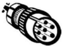
EQUIPMENT DESCRIPTION (FIG-1)
This welding machine is an inverter welding unit designed for use on refractory electrodes (TIG) in direct current (DC) and electrode welding (MMA). TIG welding requires gas shield protection of pure gas (Argon).
The MMA process can be used to weld any type of electrodes: rutile, basic, stainless steel and cast iron.
1- Positive polarity plug 5- Keyboard + buttons
2- Trigger connection 6-Gas inlet
3-Polarity plug 7-Remote control cable connector
4-Gas connection for torch 8-Power supply cable
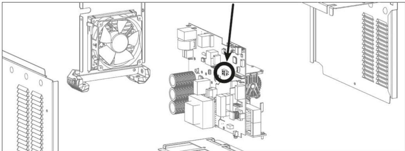
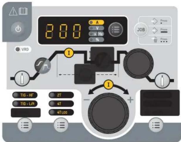
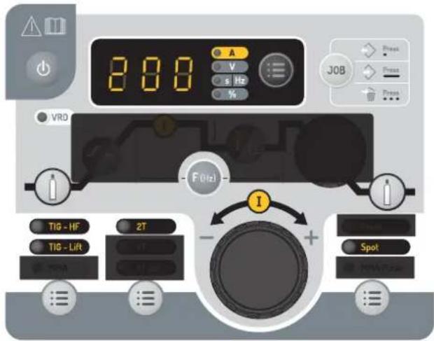
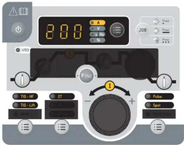
INTERFACE (MMI) (FIG-2)
1- Process section 5- Active risk reduction system indicator (VRD)
2- Trigger selection mode 6- Display and options
3- Process options selection 7- Sleep button
4-Welding parameters settings.
POWER SWITCH
The equipment is supplied with a 16A plug type CEE7/7 and must only be used on a single-phase electrical installation 230V (50-60 Hz) with 3 wires including one connected to the earth. The material integrates a « Flexible Voltage » system. It has to be plugged on a power supply variable between 110V and 240V (50 - 60 Hz) WITH earth. The absorbed effective current (11eff) is indicated on the machine, for optimal use. Check that the power supply and protection (fuse and/or circuit breaker) are compatible with the current required by the machine. In some countries, it may be necessary to change the plug to allow the use at maximum settings.
- When the power is turned on, the product starts in standby mode. The device is switched on by pressing the button
The device turns into protection mode if the power supply tension is over 265V for single phase machines. To indicate this default, the screen displays
Normal functioning will resume once the power supply is under 265V.
Fan behaviour: In MMA mode, the fan works continuously. In TIG mode, the fan works only when welding, then stops after cooling.
- The arc priming and stabilisation device is designed for manual and mechanically guided operation.
CONNECTION TO A GENERATOR
This equipment may operate with generators provided that the auxiliary power meets the following requirements:
- The voltage must be alternating, adjusted as specified and with a peak voltage of less than 400 V ,
- The frequency must be between 50 and 60Hz
It is imperative to check these requirements as many generators generate high voltage peaks that can damage the machine.
USE OF EXTENSION LEADS
All extension cables must have an adequate size and section, relative to the machine's voltage. Use an extension lead that complies with national safety regulations.
| Voltage input | Length and thickness of the extension lead | |
| <45 m <100 m | ||
| 230 V 2.5 mm² 2.5 mm² | ||
| 110 V 2.5 mm² 4 mm² | ||
GAS CONNECTION
This equipment is equipped with two connections. A cylinder connector for the gas inlet into the station, and a torch gas connector for the gas outlet at the end of the torch. We recommend that you use the adaptors supplied with your set to ensure an optimal connection.
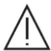
ACTIVATION OF THE VRD FUNCTION (VOLTAGE REDUCTION DEVICE)
This device protects the welder. The welding current is delivered only when the electrode is in contact with the part (low resistance). As soon as the electrode is removed, the VRD function lowers the voltage to a very low value.
The VRD function is disabled as standard. However, this can be activated by means of an ON/OFF switch on the power source control board. To access it, follow the steps below:
1.DISCONNECT THE PRODUCT FROM THE POWER SUPPLY BEFORE HANDLING.
2. Remove the screws to take the power source cover off.
3. Locate the switch on the main board (circled in the diagram below).
4. Turn the switch located on this control card ON.
5. The VRD function is activated.
6. Screw the power source cover back on.
7. On the interface (HMI), the VRD function LED is lit.
To deactivate the VRD function, simply turn the switch located on the control board back to OFF. The VRD LED on the HMI is turned off.
RESETTING THE WELDING STATION
It is possible to restore the factory settings of the welding machine. This advanced setting is accessed by pressing the «A or V display switch » button for more than 3 seconds. Then select «lni». The station then displays «3», «2», «1» and then resets the unit.
FUNCTION, MENU AND PICTOGRAM DESCRIPTIONS
| FUNCTION PICTOGRAM | TIG DC | MMA | Comments | |
| HF ignition TIG process with HF ignition HF | ✓ | |||
| Lift ignition TIG process with LIFT ignition | ✓ | |||
| Pre-gas Time to purge the torch and to protect the area with gas before ignition | area with gas before ignition | |||
| Up slope current Up slope current | ✓ | |||
| Welding current Second welding current | ✓ | |||
| Cold current/Background current) | I | ✓ | Second welding current or «cold» current in standard 4TLOG or in PULSE mode | |
| PULSE frequency PULSION frequency of the PULSE mode(Hz) | ||||
| Down slope current. | ✓ | Down slope current to minimum current, I Stop (S) to prevent weld defects and craters. | ||
| Post-gas | ✓ | Duration for which gas is released after the arc has stopped. It protects the weld pool and the electrode against oxidation when the metal is cooling (S). | ||
| HotStart Adjustable overcurrent at the beginning of the welding (%) | ||||
| ArcForce | ✓ | Overcurrent delivered to avoid sticking when the electrode enters the welding pool | ||
| TIG PULSE Pulse mode | Pulse | ✓ | ||
| TIG SPOT Spot Mode | Spot | ✓ | ||
| TIG SPOT PULSE | Spot & Pulse | ✓ | Pulse spot Mode | |
| MMA PULSE MMA process in PULSE mode | in PULSE mode | ✓ | ||
| 2T 2 time torch mode | 2T | ✓ | ||
| 4T 4 time torch mode | 4T | ✓ | ||
| 4T LOG 4 time LOG torch mode | 4TLOG | ✓ | ||
| Ampere (unit) Amperes unit for welding current settings | ✓ | |||
| Volt (unit) Volt unit for displaying welding voltage | ✓ | ✓ | ||
| Second or Hertz (units) Seconds or Hertz unit for time or frequency settings | ||||
| Percentage (unit) Percentages unit for proportionate settings | ||||
| Display switch A or V Switches the display of voltage of current during and after welding | ||||
| Program menu access Access to configuration menu save, save, ... | ||||
| Risk-reducing device Standard picture/Rmbol indicating the status of the VRD function | ||||
| Sleep mode Sleep mode | ✓ | ✓ | ||
HMI OPERATION AND DESCRIPTION OF ITS BUTTONS
| Sleep Mode / Sleep Exit This key is used to activate or exit the standby mode. Activation of the mode is not possible when the product is in welding condition. Note: When the power is turned on, the product starts in standby mode. | |
| TIG - HF TIG - Lift MMA | Welding process selection button This button is used to select the welding process. Each successive press/release switches between the following welding processes: TIG HF / TIG LIFT / MMA. The LED indicates the selected process. |
| 2T 4T 4TLOG 3 | Trigger mode selection button This button is used to set the trigger operation mode of the lamp. Each successive press toggles between the following modes: 2T / 4T / 4T LOG The LED indicates the selected mode. Note: the trigger mode selected by default at machine startup corresponds to the last trigger mode used before the last sleep or shutdown. For more information, refer to the section «Compatible Torches and Trigger Behaviour». |
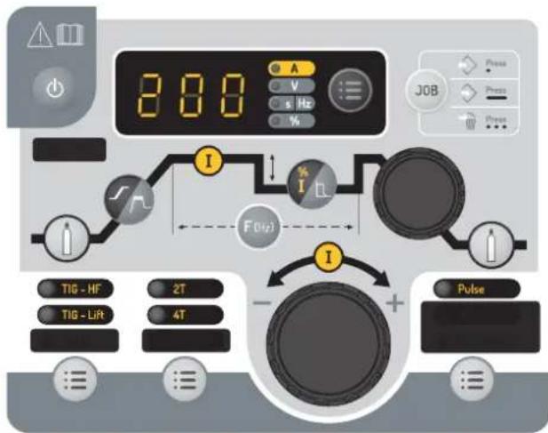
| Pulse Spot MMA Pulse | Process options selection button This key allows the selection of the «Sub-process». Each successive press toggles between the following modes: PULSE / SPOT / SPOT-PULSE (only in TIG mode) / MMA PULSE (only in MMA mode). The LED indicates the selected process. Note: SPOT mode is not accessible in 4T & 4T Log trigger configuration and in MMA PULSE welding mode. MMA PULSE welding mode is not accessible in 4T & 4T LOG trigger configuration Note: the sub-process selected by default at machine startup corresponds to the last sub-process used before the last sleep or shutdown. |
| - + | Main incremental encoder By default, the incremental encoder allows the setting of the welding current. It is also used to set the values of other parameters which are then selected via the associated keys. Once the setting is set, it is possible to press the key of the setting that has just been set again so that the incremental encoder is again linked to the current setting. It is also possible to press another key related to another parameter to adjust it. If no action is performed on the HMI for 2 seconds, the incremental encoder is again linked to the welding current setting. |
| « Pre-Gas « button The Pre-Gas adjustment is done by pressing and releasing the Pre-Gas button and then activating the main incremental encoder. Pre-Gas value increases when the incremental encoder is operated clockwise and decreases when it is operated anti-clockwise. Once the setting has been set, it is possible to press and release the Pre-Gas button again to re-link the main incremental encoder to the current setting or to wait for 2 seconds. The setting step is 0.1 sec. The minimum value is 0 sec. and the maximum value is 25 sec. | |
| « Post gas « button The Pre-Gas adjustment is done by pressing and releasing the Pre-Gas button and then activating the main incremental encoder. Post-Gas value increases when the incremental encoder is operated clockwise and decreases when it is operated anti-clockwise. Once the setting is set, it is possible to press and release again the Pre-gas button to re-link the main incremental encoder to the current setting or to wait for 2 seconds. The setting step is 0.1 sec. The minimum value is 0 sec. and the maximum value is 25 sec. The default value is 6sec. | |
| «UpSlope» current adjustment button. The current ramp is set by pressing and releasing the current ramp button and then operating the main incremental encoder. Current ramp-up value increases when the incremental encoder is operated clockwise and decreases when it is operated anti-clockwise. Once the setting has been set, it is possible to press and release the current ramp-up button again to re-link the main incremental encoder to the current setting or to wait for 2 seconds. The setting step is 0.1 sec. The minimum value is 0 sec. and the maximum value is 25 sec. The default value is 6sec. In MMA mode, the Hotstart is adjustable between 0 and 100% of the welding current in 5% steps. The default value is 40%. | |
| DownSlope adjustment potentiometer The «DownSlope» potentiometer is used to adjust the current fade value (clockwise increment and counterclockwise decrement). The value is visible on the 7-segment display and remains displayed for 2 seconds if an action on the potentiometer is performed. The minimum value is 0 sec. and the maximum value is 20 sec. | |
| % I | Cold current adjustment button When one of the 2 processes «HF TIG» or «LIFT TIG» is selected, the cold current setting button is used to adjust the value of the cold current (only in «PULSE»). The value can be adjusted between 20% and 80% of the welding current. The incremental step is 1%. The default value is 30%. In MMA mode, the Arc Force is indexed from -10 to +10 (-10 = no Arc Force / -9 to +10 = Arc Force setting possible). The default index value is 0. |
WELDING WITH RUBBERED ELECTRODE (MMA MODE)
CONNECTIONS AND RECOMMENDATIONS
- Connect the electrode holder and earth clamp to the corresponding sockets.
- Ensure that the welding polarities and intensities indicated on the electrode packaging are observed.
- Remove the electrode from the electrode holder when the machine is not in use.
CHOICE OF COATED ELECTRODES
- Rutile electrode: very easy to use in all positions with DC current
- Basic electrode: used in all CC positions, it is suitable for safety work due to its increased mechanical properties.
MMA STANDARD
This standard MMA welding mode is suitable for most applications. It allows welding with all types of coated electrodes, rutile, basic and on all materials: steel, stainless steel and cast iron.
MMA Standard
The grey areas are not useful for this mode.
| Designation Setting Description | tion & advice | |
| Percentage of Hot Start 0 - | 100 % | The Hot Start is an overcurrent during priming to prevent the wire from sticking to the part to be welded. It is set in Intensity and Time. |
| Welding current 10 - 200 A | The welding current is adjusted according to the type of electrode chosen (refer to the electrode packaging). | |
| Arc Force -10 / +10 | The Arc Force is an overcurrent delivered when the electrode or drop comes into contact with the solder bath in order to avoid sticking. |
Pulse MMA
This MMA Pulse welding mode is suitable for applications in the vertical up position (PF). The pulse mode keeps the weld pool cold and eases the transfer of matter. Without the pulse mode, vertical-up welding requires a difficult «Christmas tree» shape triangular movement. With the MMA Pulsed mode, this movement is no longer required and a simple straight up movement is enough (depending on the thickness of the workpiece). If you wish to widen your weld pool, a simple lateral movement is enough (similar to standard welding). This process allows greater control during vertical-up welding.
The pulse frequency is adjusted by pressing and releasing the «F(Hz)» button and then activating the main incremental encoder. Frequency value increases when the incremental encoder is operated clockwise and decreases when it is operated anti-clockwise. Once the setting is set, it is possible to press and release again the «F(Hz)» button to re-link the main incremental encoder to the current setting or to wait 2 seconds.
MMA PULSE

The grey areas are not useful for this mode.
| Designation Setting Description | tion & advice | ||
| Percentage of Hot Start 0 - | 100 % | The Hot Start is an overcurrent during priming to prevent the wire from sticking to the part to be welded. It is set in Intensity and Time. | |
| Welding current 10 - 200 A | The welding current is adjusted according to the type of electrode chosen (refer to the electrode packaging). | ||
| Pulse frequency 0.4 - 20 Hz | Pulsation frequency of the PULSE mode. The incrementation step depends on the frequency range: | ||
| Pulse frequency Incremental step | |||
| 0.4 Hz - 3 Hz 0.1 Hz | |||
| 3 Hz - 20 Hz 1 Hz | |||
| Arc Force -10 / +10 | The Arc Force is an overcurrent delivered when the electrode or drop comes into contact with the solder bath in order to avoid sticking. | ||
MMA - Advanced menu
Additional settings can be accessed in the advanced menu.
These advanced settings can be accessed by pressing the button advanced settings:

for more than 3 seconds. Rotating the wheel gives access to the following
| Parameter | Description Setting Standard Pulse Recommendations | ||||
| « AST » Anti-Sticking ON/OFF | ✓ | ✓ | The anti-sticking feature is recommended to safely remove the electrode in case it is stuck to the metal. | ||
| « HSt » Hot Start duration 0 - 2 s | ✓ | ✓ | The duration of the HotStart can be adjusted to make the arcing easier when using difficult electrodes. | ||
| « dcy » | Duty Cycle | 20 % - 80 % | ✓ | Time balance of the hot current (I) of the pulsation | |
| « Ico » | Cold current/Back-ground current) | 20 % - 80 % | ✓ | Second welding current known as «cold» welding current | |
The parameter to be modified is validated by pressing the button. The advanced settings menu can be exited with «ESC».
TUNGSTEN ELECTRODE WELDING WITH INERT GAS (TIG MODE)
CONNECTIONS AND RECOMMENDATIONS
- The TIG DC welding requires gas shield protection of pure gas (Argon).
- Connect the earth clamp to the positive connector (+). Connect the power cable to the negative plug (-), as well as the torch and the gas connections.
- Ensure that the torch is equipped and ready to weld, and that the consumables (Vice grip, ceramic gas nozzle, collet and collet body) are not damaged.
The electrode choice depends on the TIG DC process current.
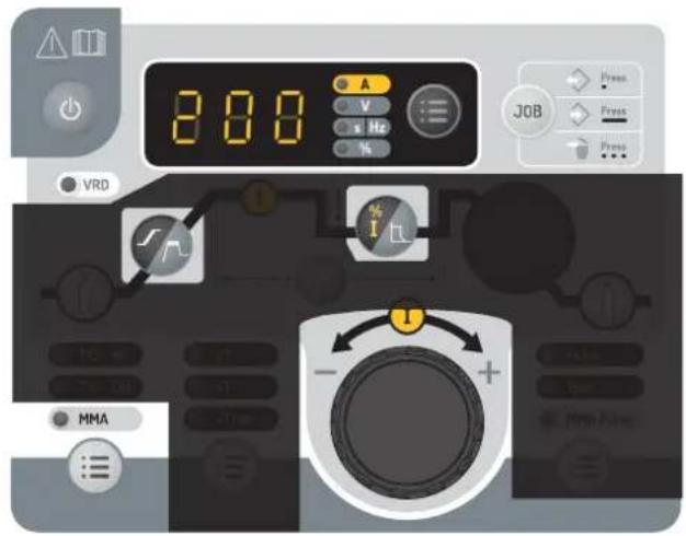
ELECTRODE GRINDING
For optimal operation, it is recommended to use a sharpened electrode as follows:
L = 3× d for a low current.
L = d for a high current
CHOICE OF ELECTRODE DIAMETER.
| Electrode Ø (mm) | TIG DC | |
| Pure tungsten Tungsten with oxides | ||
| 1 | 10 > 75 | 10 > 75 |
| 1.6 | 60 > 150 | 60 > 150 |
| 2 | 75 > 180 | 100 > 200 |
| 2.5 | 130 > 230 | 170 > 250 |
| 3.2 | 160 > 310 | 225 > 330 |
| 4 | 275 > 450 | 350 > 480 |
| Environ = 80 A per mm Ø | ||
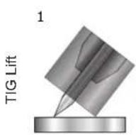
SELECT IGNITION MODE
TIG HF High Frequency start without contact.
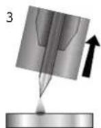
TIG Lift contact ignition (for environments sensitive to HF disturbances).
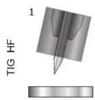
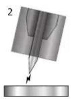
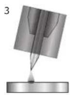
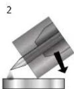
1- Place the torch in the welding position above the part (distance of about 2-3 mm between the electrode tip and the part).
2- Press the torch trigger (the arc starts without contact using High Frequency impulses).
3- The initial welding current circulates, the welding carries on according to the welding cycle.
1- Position the torch nozzle and electrode tip on the part and press the torch button.
2- Tilt the torch until a distance of about 2-3 mm separates the tip of the electrode from the part. The arc starts.
3- Put the position back into position to start the welding cycle.
Warning: Increasing the length of the torch or earth return cables beyond the maximum length specified by the manufacturer will increase the risk of electric shock.
TIG DC - STANDARD
- Standard The TIG DC Standard welding process allows high quality welding on most ferrous materials such as steel, stainless steel, but also copper and its alloys, titanium. The many possibilities of current and gas management allow you to perfectly control your welding operation, from priming to final cooling of your welding rod.
TIG DC Standard
The grey areas are not useful for this mode.
TIG DC - Pulse
This pulsed current welding mode is a combination of high current pulses (I, welding pulse) and low current pulses (I_Cold, part cooling pulse). This pulse mode allows to assemble pieces while keeping the machine cool.
Example :
The welding current I is set to a 100A and % (I_cold) = 50%, thus a Cold current of = 50% x 100A = 50A. F(Hz) is set to 2 Hz, the signal period will be 1/2Hz = 500 ms. Every 250ms, a 100A pulse then a 50A pulse will succeed each other.
Pulse TIG DC
The grey areas are not useful for this mode.
Recommendations:
Choice of frequency:
If welding with manual filler metal, then F(Hz) synchronised to the filler metal action,
If thin without filler (< 0.8mm) F(Hz) >10Hz
The pulse frequency is adjusted by pressing and releasing the F(Hz) button and then activating the main incremental encoder. Frequency value increases when the incremental encoder is operated clockwise and decreases when it is operated anti-clockwise. Once the setting is set, it is possible to press and release again the F(Hz) button to re-link the main incremental encoder to the current setting or to wait 2 seconds.
| Designation Setting Description & advice | |
| Pre-gas 0 - 60 s Time to purge the torch and to protect the area with gas before ignition | |
| Rising current 0 - 60 s Current rise ramp. | |
| Welding current 10 - 200 A Welding current | |
| Cold current/Background current) | 20 - 99 % Second welding current known as «cold» welding current |
| Pulse frequency 0.1 - 2000 Hz Pulse frequency | |
| Evacuation 0 - 60 s Down slope current. | |
| Post-gas 0 - 60 s | Duration for which gas is released after the arc has stopped. It protects the weld pool and the electrode against oxidisation when the metal is cooling down. |
TIG - Advanced menu
Additional settings can be accessed in the advanced menu.
These advanced settings can be accessed by pressing the button for more than 3 seconds. Rotating the wheel gives access to the following advanced settings:
| Parameter | Description | Setting | Standard | Pulse | Recommendations |
| « ISa » | Current threshold when starting the weld. | 10 % - 200 % | ✓ | ✓ | This current threshold is a phase before the current upslope. |
| « tSa » | Time threshold when starting the weld. | 0 s - 10 s | ✓ | ✓ | |
| « ISO » | Current threshold when the weld stops. | 10 % - 100 % | ✓ | ✓ | This current threshold is a phase before the current upslope. |
| « tSo » | Time threshold when the weld stops. | 0 s - 10 s | ✓ | ✓ | |
| « dcy » | Duty Cycle | 20 % - 80 % | ✓ | Time balance of the hot current (I) of the pulsation |
The parameter to be modified is validated by pressing the button = . The advanced settings menu can be exited with «ESC».
SPOT welding
This welding mode allows the pre-assembly of parts before welding. Scoring can be manual by trigger or delayed with a predefined scoring delay. This spot timer allows for a better reproducibility and the realisation of non-oxidized spots (accessible with the «F(Hz)» button).
TIG SPOT
The grey areas are not useful for this mode.
| Description Setting Recommendations | ||
| Pre-gas 0 - 60 s Time to purge the torch and to protect the area with gas before ignition | ||
| Welding current 10 - 200 A | Welding current | |
| Spot Man, 0,1 - 60 s Manual or a defined time. | ||
| Post-gas 0 - 60 s | Duration for which gas is released after the arc has stopped. It protects the weld pool and the elec-trode against oxidisation when the metal is cooling down. | |
SPOT PULSE welding
This welding mode on thin sheet metal allows the pre-assembly of parts before welding. Scoring can be manual by trigger or delayed with a predefined scoring delay. This spot timer allows for a better reproducibility and the realisation of non-oxidized spots (accessible with the «F(Hz)» button).
TIG PULSE SPOT
The grey areas are not useful for this mode.
| Description Setting Recommendations | ||
| Pre-gas 0 - 60 s Time to purge the torch and to protect the area with gas before ignition | ||
| Welding current 10 - 200 A | Welding current | |
| Spot pulse Man, 0,01 - 60 s | Manual or a defined time. | |
| Post-gas 0 - 60 s | Duration for which gas is released after the arc has stopped. It protects the weld pool and the electrode against oxidisation when the metal is cooling down. | |
SAVE AND LOAD WELDING SETTINGS
The current settings are automatically saved and loaded at start up. In addition to the current settings, it is possible to save and recall so-called «JOB» configurations. The « JOB « button is used to save, recall or delete a configuration. 50 Jobs can be stored per welding process.
Job creation
- Adjust all desired welding parameters,
- Press and hold the «JOB» button for more than 3 seconds.
- IN appears on the display,
- Select a job number using the incremental encoder. Only numbers that are not already associated with a previously saved job can be selected and are indicated on the display,
- Once the job number is chosen, press the «JOB» button to validate and save it under the selected number,
- The job number is then displayed, indicating that the job has been saved. The number continues to be displayed until another button or the torch trigger is activated.
Note: If all numbers are already assigned to saved jobs, the HMI displays «Full».
Job recall
Apart from not being in the process of welding, the job recall does not require any particular initial condition:
- Press the «JOB» button briefly (not exceeding 2 seconds),
- «OUT» appears on the HMI display,
- With the incremental encoder, select a job number. Only the numbers associated with existing jobs appear on the display. If no job is stored, the HMI displays - -
- Once the job number is selected, press the «JOB» button to confirm the configuration. The job number then flickers on the display, indicating that the job was loaded. The number continues to flicker until another parameter is changed or until the torch trigger is pressed to start the welding cycle.
Job deletion
- Press the «JOB» button briefly (not exceeding 2 seconds),
- «OUT» appears on the HMI display,
- With the incremental encoder, select a job number. Only numbers associated with existing jobs can be displayed,
- Press the « JOB » button 3 consecutive times. The selected job is now deleted and the power source
displays the welding current again.
RECOMMENDED COMBINATIONS
| ↓↑ | Current (A) Electrode | (mm) Shroud (mm) Argon flow rate (L/min) | |
| 0.3 - 3 mm 5 - 75 1 | 6.5 6 - 7 | ||
| 2.4 - 6 mm 60 - 150 | 1.6 8 6 - 7 | ||
| 4 - 8 mm 100 - 160 | 2.4 9.5 7 - 8 |
COMPATIBLE TORCHES AND TRIGGER BEHAVIOURS
| Trigger | DB | P |
| Double Buttons | Double Buttons + Potentiometer | |
| ✓ | ✓ | ✓ |
For the 1 button torch, the button is called «main button».
For the 2 buttons torch, the first button is called «main button» and the second button is called «secondary button».
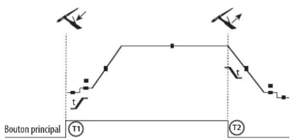
2T mode:
4T MODE
T1 - The main button is pressed, the welding cycle starts (PreGas, I_Start, UpSlope and welding).
T2 - The main button is released, the welding cycle is stopped (DownSlope, I_Stop, PostGas).
For the double button torch and in 2T mode only, the secondary button works like the main button.
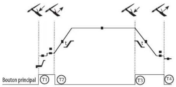
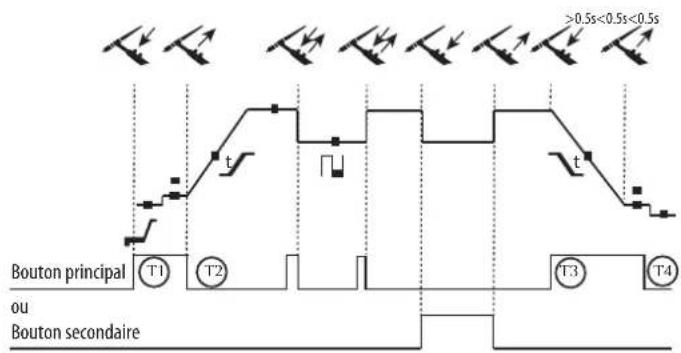
4T MODE log
T1 - The main button is pressed, the cycle starts from the PreGas and stops in the I_Start phase.
T2 - The main button is released, the cycle continues in UpSlope and in welding.
T3 - The main button is pressed, the cycle switches to DownSlope and stops in I_Stop.
T4 - The main button is released, the cycle ends with PostGas.
For the dual-button torch, the secondary button is inactive.
T1 - The main button is pressed, the cycle starts from the PreGas and stops in the I Start phase.
T2 - The main button is released, the cycle continues in UpSlope and in welding.
LOG: this operating mode is used in the welding phase:
- A short press of the main button (<0.5s) switches the current from I welding to I cold and vice versa.
- the secondary button is kept pressed, the current switches from I welding to I cold.
the secondary button is released, the current switches from I cold to I welding.
T3 - A long press on the main button (>0.5s), the cycle switches to DownSlope and stops in the I_Stop phase.
T4 - The main button is released, the cycle ends with PostGas.
For this mode it may be convenient to use the dual button torch option or dual button with potentiometer. The «up» trigger keeps the same function as the single button or trigger torch. The «down» button can, when pressed, switch to the cold current. The potentiometer of the torch, where available, can control of the welding current from 50% to 100% of the value displayed.
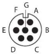
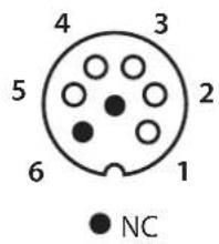
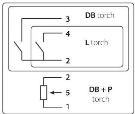
TRIGGER COMMAND CONNECTOR
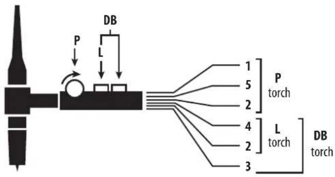
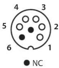
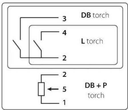
Wiring diagram according to the type of torch. Electric diagram based on type of torch used.
| Torch type Wire description Pin | ||||
| Torch double button + potentiometer | Torch double button Torch with trigger | Common/Earth 2 | ||
| Button 1 4 | ||||
| Button 2 3 | ||||
| Common/Potentiometer earth | 2 | |||
| 10 V 1 | ||||
| Cursor 5 | ||||
REMOTE CONTROL
The analog remote control operates in TIG and MMA processes.
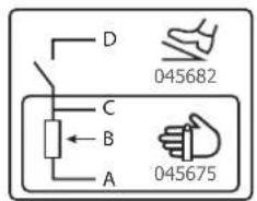
Ref. 045699 External view Electric diagram according to the remote control type.
Connection
1- Plug the remote control into the connection at the back of the machine.
2- The HMI detects the presence of a remote control and offers a selection choice accessible by wheel.
Connections
The product is equipped with a female socket for a remote control.
The specific 7 pin male plug (option ref. 045699) allows the connection of different types of remote control. For the cabling layout, please see the diagram below.
| Wire description Pin | |||
| Foot pedal Manual remote control | 10 V A | ||
| Cursor B | |||
| Common/Earth C | |||
| Switch D | |||
Operating:
- Manual remote control (option ref. 045675):
The remote control enables the variation of current from 50% to 100% of the set intensity. In this configuration, all modes and functions of the machine are accessible and can be set.
Foot pedal (option ref. 045682):
The foot pedal allows the current to be set from 10% to 100% of the set current. In TIG, the welding machine only operates in 2T mode. The upslope and downslope are not automatically managed by the current source, and are controlled by the user with the foot pedal.
RESOLUTION DES PROBLEMES
This device integrates a default management system.
A series of messages displayed on the control board allows for a fault and anomalies diagnosis.
| Error code Meaning CAUSES SOLUTIONS | |||
| EH° | Thermal protection | Maximum duty cycle reached.Ambient temperature above 40°C.Obsstructed air input. | Wait for the indicator to turn off before resuming welding operations.Observe the operating factor and ensure good ventilation |
| US1 | Mains overvoltage fault | Mains voltage outside maximum tolerance(230V single-phase +/- 15%) | An overvoltage on the electrical network is at the origin of the message.Have your electrical installation or genera-tor checked by an accredited person. |
| USc | Torch fault Faulty torch(es) trigger(s)/ button(s) | Make sure that nothing presses the torch trigger(s) when the product is switched on. | |
| USd | Pedal fault The pedal is pressed down | Make sure that nothing presses on the foot pedal when the product is turned on. | |
| EBP | Push button(s) fault Push button(s) short-circuited | Check that none of the push buttons are pressed | |
| Troubleshooting Causes Solutions | |||
| TIG-MMA | The indicator is on but the product does not deliver any current. | The earth clamp or the electrode holder is not connected to the unit. | Check the connections |
| The product is connected to the mains, you are feeling tingling when touching the car body. | The earth contact is faulty. | Check the plug and the earth of your installation. | |
| The machine welds poorly. Polarity error | Check the recommended polarity (+/-) on the electrode box. | ||
| TIG | Unstable arc | Fault due to the tungsten electrode | Use an electrode size more suitable to the thickness of your metal. |
| Use an tungsten electrode properly prepared. | |||
| Use a tungsten electrode that is suitable for DC. | |||
| Gas flow incorrectly set | Check the gas flow rate on the cylinder pressure gauge. | ||
| The tungsten electrode becomes oxidized and tainted at the end of the welding | Gas problem, or gas flow stops too early | Check and tighten every gas connection. Wait for the electrode to cool down before switching off the glas flow. | |
| The electrode melts Polarity error | Check that the earth is connected to the (+) ant the torche to the (-) of the product | ||
WARRANTY CONDITIONS
The warranty covers defaults or manufacturing defects for 2 years from the date of purchase (parts and labour).
the warranty does not cover:
- Any other damage due to transport.
Normal wear of parts (eg.: cables, clamps, etc.). - Damages due to misuse (power supply error, dropping of the equipment, disassembling).
- Environment related failures (pollution, rust, dust).
In the event of a malfunction, return the unit to your dealer, enclosing:
- a dated proof of purchase (till receipt, invoice...)
- An explanatory note of the failure.
HnB KOem cnyyae He Bapntb B6nn3n Jkpa nJn Kpackn.
PICKIOKAPAIB3PbIBA

NoHocTbO 3aunntte 30Hy CBapKn. Bo3ropaemble MaTePnAbI DoNkHb6bTy ydaenHka KAK MNHMym Ha 11 MetpoB.
IpotnoBOnoKapHoe o6opynobAHne DoNkHO HaxoDnCB B6n3n npoBeHn CbaOpHbIX pa60T.
Octopoxho 6pbI3ramrnpaero Maepnana nncp. OHm Moryt nobney 3a c06o npkap nB3pbIB daxe uepe3 eenn
YdaIte IIOe, Bo3ropaemble npeMeTb IN BCE emKocn noD daBHeHem Ha 6e3onacHoe pacctOAHne.
Hn B KOem cnyae He Bapnte B KOHTeHepax nnn 3akpbTbIX Tpy6ax. B cnyae, ecln OHn OTkpbl, To neped CBAPKO IH Hx HyxHO OCBOOHTb OT BCEx B3pBbATbIX INN BO3ropaEMbIX BeueCTB (Macno, TonlNO, OCTaOTHHe ra3bl ...).
Bo Bpem Oepaunu Hnnpabra Te nHCTpymEnB CTOpOHy NcToHHKa CBapOHOro ToKa IIN BO3rpaembIX MaTePnaNoB.
T3OBbIEBAJIIOHbI

Tg3OM, BbIXOJaIM N3 ra3OBbIX 6aIIOHOB, MoXHO 3aDOxHybC B Cnyae erO KOHcHTpaunn B NOMeueHN CBapKN (XopoOIO npoBeTpuaTe).
TpaHcnopTpOpBka DOnJkHa 6bTB BbINoHHe 6e3oNaCHO: UINHHpbl 3aKpbbl, a NCTOCHK CBAPOHOr TOKa BbIKIOueH. BaIIOHO bdoJHKb6bTB BepTKaJIbHOM NOIOKeHN H 3aKpenneHb Ha NoCTaBKe, YTObI OPAHHTb PnCK naDeHnA.
3aKpbBaiTe 6aannoh B nepepbBe MeJy DByMg NcNoIb3OBAHnMn. ByIbe TBHMaTeNbHbI K NImHeHIO TempeaTpybl I ppe6bBaHnHO ha cOnHlce.
BaanH He donxkeH cnpnKacatbca C nnaMeHem, 3neKtpueecko Dyro, ropeKo, 3axmOM Maccbl NIN C IIObIM dpyHM hctOHNKOM TENla nn CBeueHn.
Eepxnte ernoaIbwe ot 3neKtpnuecknx n CBAPOHybIX cenei, CneIOBaTeNbHO, HIKoRda He Bapnte 6aannOH noD daBHeHem
Bbte Bnmatbbl: npn OTkpbltn BeHTnla 6aIIOHa y6epnte rnoby ot BeHTnla n y6eintecb, YTO NCNOb3yEmbl ra3 COOTBeTCTByet MeToDy cbapkn.
3JIKTPNUECKA B3OJNACHOCTb

Ucnno3yema 3neKtpueckc aetb doJxHa o6a3aTeNbHO 6bTb 3a3emHNo. Co6nOdaTe kaH6p npdoxpaHtTeYkzaHHb Ha annapate.
3NeKtpueeckn pa3pnd MoKeT BbI3BaTb npAmbie NIN KOCBeHHbIe paHeHNA, IN daXe CmepTb.
Hikorda He doTparBaItecb Do uactei noi HapxHnem Kk BHytp, TaK n ChapyxN nCTOuyHka, KOrda OH noi HaipxHeHem (ropeKN, 3axMbI, Ka6en, 3neKTpobl), T.K. OHnnoKIOUeHbIK CBAPoHoi cenn.
IpeeTeM, KaK OTKpbITb NCTOCHNK, ERO HyxHO OTKIIHouHTb OT CEtN I NOIOXJaTb 2 MNHyTb IINr TORO, YTO6bI BCE KOHDeHCaTOPbI pa3pAINlncB.
HnKorda He doTpaHbAaTeCb oDnOBpeMeHHo Do ropeKN uNn 3neKtpdoepKaTeIe N do 3axkmaMaccbl.
Ecn Kabenn, ropEnKn NOBpeKJeHbI, nonpocnTe KbaInnPhiuNPOBaHHbIX u yOnlHMOeHHbIX CneuaJIncTOB IN 3aMeHNb. Pa3Mepbl ceehnna Ka6enei dOxHb CoOTBeTcBOBaTb npmehenIO. Bcerda Hocnte cyxyIO OeJy B XopoWem COCToHnn DnI N3OJaUN OT CBAPoHou cEN. Hocnte I30npyiouyo obvBy He3aBNCIMO OT ToI cpebl, rde Bbl pa6oTaTe.
KJIACCNUKAKUNA 3JEKTPOMAHHTHON COBMECTMOCTN

3To o6bpyoBAAHn KIACCA A He nOxOHT IIN cNIOb3OBAHn B XINbIX KBaPTanax, Ige 3NeKTPuyeckn TK NOaetcnoBtceBHeHHOn CnCTeMoH NITAHn HN3KOHO HApJXeHn. B TAKNX KBaPTanax MOrY BT O3NHkHyTb TpyHocTN ObecneHn3JIeKTPomarHHTyO COBMeCTMOCtB I3-3a KOHdyKTNBbIx IN HNDyKTNBbIX NOMex Ha paDmoAcTOTe.
Pn yCIOBm, YTO COpOuBbIeHne H3KOBONbTHoN CTeN O6UeO NITAHN B O6Ue ToKe CoEINHeHMeHbSe Zmax = 0.173
OM, 3TO o6OpOyOBaHHe COOTBeTCTByET IEC 61000-3-11 M0XeT 6bTb NOKIIHOeHO K H3KOBONbTHbIM CeTAM O6UeO NITAHN.
CneuaIACt, YCTaHOBuBwI aIcapaT, INI NOLb3OBAteNB, DOJXHbI y6eITbcr, O6paTUBWncb PnHaIObHOcTN K OprAHN3aUN
OTBeauOJe 3a 3KcPiYaTaUH CnCTeMbI NITAHN, B TOM, YTO ee NOLHOe COpOuBbIeHne COOTBeTCTByET PpeDenam NOnHOro
CONpOuBbIeHn.
3TO o6OpOyOBaHHe COOTBeTCTByET HopMe CEI 61000-3-12.
MAGHTHBIE NOJIA
3NeKtpnueckn TOK, npoxoJauu chpe3 IIO6o npOoHb Kbl3bBaet NokaHn3oBaHHbe 3NeKtpomarHHTbIe non (EMF). CbaOpHHbTOK Bbl3bBAeT 3NeKTPomarHHTHOE NOE BOKpyc CBapOCHOH cBapOCHORO o6opdyOBAHNA.
Bce cbapuKn doJXHbI cnoNb3oBaT cneDyUOUIne npOeDpybl IaM MHNMM3aunn BO3dEChTBn 3NeKtpomarHHTbIX nOEi:
paonnooxnTe CBapouhNbe Ka6eNn BmecTe - NO Bo3MOXHOCTN 3aKpeNITe INC NOMOuBIO 3aXIMa;
-ДерхиТecьКAKMOЖHOДальшOTCBAPOчHOnцпн
Hn B Koem cnyuae He obopaunBaIe BOKpyr ce6ra CBAPouhIke Ka6eJI.
- He pa3MeuauTe KOpnyc MExdy CbApOHybIMn Ka6eIaMn. DepeKInTe 06a CBApOHybIX Ka6eIHa OndHcTopoHe Kopnyca;
-ПодсоeДинTe o6paTHbI Ka6eIb K 3aTOrTOBKe KaK MoXHO 6JInke K CBapNBaEMOMy yUaCTKy;
He pa6oTaIe pIaOM, He caIITecb I He npCIOHOJItecB K nCTOCHNky CBAPOHTO ToKa;
- He CBAPINBaTb npn TpaHcnpOpTnOBKe nCTOuHnka CBapOHoro TOKa nn yCTpOnCTBa nOaun npoBOJOKn.

Iiua, nCnoB3yUoHne 3JekTpokapDIOCTMMyTApOpbI, DOnKHBIpOKOHcyNbTIpOBAbCBy Bpaaypepepa60Toc daHHbIM o6opuyoBaHnEM.
Bo3eCTBnE 3NeKtpomarHHTHO NOB B PPOEcCe CBAPKIMoKET IMeTb N DpyrHe, eue He H3BeCTHbIe HayKe, nocJeCTBnI dIy 3DopOBbJ.
PEKOMEHDAUIN DJIY OUEHKN 3OHbI CBAPKN I CBAPOHON YCTAHOBKN
06uue CBeDeHHa
Ponb30aTeBbOTBeaet 3a yctahOBky n cnoIb3oBaHne ycTaHO BpyHO DyROB CBAPKn, cneDyra Yka3AHnM npOn3BOHTeTEn. PnO6hApyeHNn 3EeKTPOMaHTbIX 3nlyueHn nnb3oBAten annapata pyHO DYBOB CBAPKn DOxKe HpaOpMeN pO6bme N CMOUcBTOexHcckO nOpeKnn PON3BOHTeBn. B HeKToBx CnyAax 3To KOPpeKTHpyHOe DeiCTBne MoKet 6bTb DoCTaTOH NOpCTbIM, HAnpMep 3a3emHe CBAPoHOr CEIN. B Dpynx CnyAax Bo3MOxHO Notpe6yeTc Co3dAHH eJNEKTPOMaHTHORo 3kpaHa BOKpy NcTOHnKa CBAPoHOr TOk A BcE hCBAPuBAeMoH DeTANn PyTeM MOHTPOBaHn BXODbX FInbTpoB. B IIO6OM CNYae 3NEKTPOMaHTHtHe I3NPyehn DaONKbI 6bITyMeHbWeHb TAK, YTO6bl OHI 6OJIbHe CO3DaBaN nomEx.
OueHka CBapoHoi 30HbI
Pepd yctahOBkOyobAHnrydyroBcBapKn noIb3oBaTeNb DOJKeH OueHNb BO3MOXHbE 3NeKtpMaTHHbIe np6JIeMbI, KOtOpBie Mory B03HNKHyTB B OKpykaOuSe cpe. YTO donxHO 6bTb yTeHo:
(a) HauHne HAD, NOI pRdOM C o6OpOBAHnEM dIyroBcBapKn Dpynx CInOBbIX, ynpabJIOxN, CNHaNbHbIX n TenefoHHbIX Ka6eJIe; 6)PpemHnIKn I nepeDaTCHNK paDIO N TeNEBnDEHnI.
(B) KOMNbIOTepBn I npyroe KOHTpONbHOe O6OpyObaHne;
r) obopydobAHne, mHeoee peaiooee 3NaueHne nIe 6e3onacHOCTn, Hapmep 3auNTa npombuHoro obopydoBaHnra;
D) 3dopOBBe IIODei, KOtOpbIe HaxoJrTcR No6n3OCTHnHapmep, npn nCNoJIb3OBAHmN KApDIOCTMMyJrTOpOB uIN CnyXOBbIX annapaTOB;
(e)obopydOBaHHe,NCIOJIb3yEmoeIgKaJIIN6pOBKnIINI3MepeHnra;
(x)HEBOCpHmMnBOcTbDpyrOoobopydOBaHnKOKpyKaUoJeCpeJe.
IoiB30BaTeJI DoJIKeH y6eITbC8 B TOM, YTO BCE anIIapatbl B NOMEueHH COBMeCTIMbl dpyr C dpyrom. 3To MOxET nOJIHNHTeJIbHbIX 3aUHTbIX Mep;
(Ⅲ)ВремаCyTOK, KOrdaДоЛЖнbl npOBODnTbca CBapOHyIe IINpyrme pa60TbI.
Pa3Mepb paaccMatpmbaem0 30Hb CBAPKn 3aBncrT O ctpkTypb 3daHn n dpynx pa6oT, KOtOpbE B HEM npOBOraTc. PaccMaTPBaemar 30Ha MoKet npocatpaTbc 3a npedeIb pa3MeueHn yCTaHOBKn.
OueHka CBapouHoi yCTaHOBKn
IOMMIO OueHKN 30HbI, OueHKa annapaTob pyHOn dyroBcBapKn MoKet NmOy bOpTeHNb NpeuNTb Cnuyan 3neKtpomarHHTbIX nomex. OueHKa n3nyen HdoJxHa yUThBaTb N3MepeHn B ycNoBnx 3KnNyataun, KaK 3TO yKa3aHO B CtaBe 10 CISPR 11:2009. 3MepeHn B ycNoBnx 3KnNyataun MOrTy TAKKe NsOBnTb NODTBepnTb 3ΦΦeKTHBHOCTb MEP No CMrYeHIO BO3dEChBnR.
PEKOMEHDAUINI NO METODNIKE CHNXEHNIAJEKTPOMAHHTHOI N3JIyEHNIA
a.ObseCTBeHHa Cetb Ch6KeHn: ObopyOBaHHe dny DyROB CNapK DoJNHO 6bTb NOKIOeHO K O6IeCTBeHHOMY 3NeKTPoCHa6KeHnIO B COOTBETCBn CpeKomeHdaCnMn PpOIN3BODInTeBn. B CNYae BO3HNKHOBEHn NOMEX BO3MOXHO 6yET He06xOJIMo pINHrTb DOONIHNTeBhIbe PnpDynPeDInTeBnHbIe Mepbl, TaKne KaK FInbTpauu O6UeCTBeHHo CICTeMb NITAHN. Bo3MOXHO 3aUNHTb SHyp NITAHN ANPapaTa C NOMOUH 3KpaHn3pyUOe ONNtKn, NIOo NOXOKMm PncnOC6BHeHem (B CNYae eCN AnnapaT pyHou DYROB CNpOCTOHNO HAXOnTcHn OnpEDEHNNPOBaOChMeCTe). He06xOJIMo o6ecneHb 3NEKTPuYeCKy HENpepbHBocTH 3KpaHn3pyUOe ONNtTKn NO BcE dINHe. He06xOJIMo NOCoEduHb 3KpaHn3pyUOyO ONNtTKy K ITOUHNIky CBAPoHORo TOKa DnR o6ecneHHe XopoWero 3NEKTPuCeCKOro KOHTa MExdy WHPom I Kopnycom hctOHHa CBAPoHORo TOKA.
6. Texnueckoe 0cbnykBaHne 0bOpDobAHnI dnyroBo CBAPKn: O6opyoBaHne IydyroBo CBAPKn DOnxHO pOxOHTB peryrnapHe TcHmCheKoe 0cbnykBaHne B COOTBCTBn C peKOMeHaaunnn PPO3BOJTeNn. Heo6xoJIMO, YTO6bl Ce DocTyNbl, IIOKN i OTKnDbBAUHeceA cTtN KOPynCa 6bln 3akpybl N npabNlHo 3akpenJIeHbl, KOra annpaT pyHOr DYROB CBAPKn rOtOB K pa6Ote Hn HaxOHTCB B pa6OeM coCTOHN. Heo6xoJIMO, YTO6bl annpaT pyHOr DYBOB CBAPKn He 6bl npeDeNaH KAKIM 6bl To Hn 6bl NO o6pa3OM, 3a NCKIOuChennE M hAcTpoE, yka3AnhBx By pKOBODCTBe npO3BOJTeNn. B UactHOCTn, cJeMyET OtpErYIpOBAbI N ObCnykNBAtb NCKPOB IpOMexyTok Dyrn YCTPOCTB NdoKInra n CTa6nIN3aunn Dyrn B COOTBCTBn C peKOMeHaaunnn PPO3BOJTeNn.
B.CBAPOUHbIE KABEN CnIOBbIe Ka6en: Ka6en DoJXhbl 6bITb KaK MoXHO KopoYe n NOMEuHbI dpyr praOM c Dpyrom B6n3n OT noLa nn Ha nony.
r. 3KBNOTeHnAJIbHoe coeHNHeHne: 3KBNtOeHnAJIbHbIe coeHNHeHne: Heo6xoJIMO o6ecneHTb coeHNHeHne BcEx MeTaNlUeCKNX npdMetOB OKpykaIOeI 30HbI. TeM He MeHee, MetaJIINueCKNe ppeMeTbI, coeHNHeHbIe CO CBAPNAeMOI dTaJIbO, yBEnNUBAOT PnCK I nONb3OBaTeN rYdapa 3NeKtpuYeCKIM TOKOM, ecNI OH OJHOBpeMeHNO KOCHeTcR aTNX MeTAJIInueCKNX npdMetOB N 3JeKTpOda. OnpaTop DoJnx H 6blb N3OpnoBaH OT TAKNX MToJIInueCKNX npdMetOB.
3aemnne 3arotobk: 3aemnne Cbapnaem Deta: B cnnyae, ecnn cbapnaema J He 3aemnne H no coo6paeHnM 3eKtpnueck0 be3onacnoctn HnB CNYB CBOxP a3MePOB u CBOero pacnoNoXeHnA, Ka, Hanpimep, BCnyae Kopnyca cyHa Nm MeTaIIOKOHOCTpyKu nPiomblneHHoro o6BeKaT, To cOeHNHeMe DetanC 3eMNe, MOKeT B HEKOTOpBX CUYARX, HO He CNCTeMaTHeCKN, COKpaTINb BB6PoCb. Heo6xoDIMO 136eBaTc 3aemnne He DeTaeJe, KOToPbe MoRn 6bI yBEInHtB nIbn3ObaTeN pNc PAnHeH Nn I ne OOBpeDn Dpyrme 3eKnTPOyCTaHOBKn. Pn HAdo6Hocn, Cndyet Hapmyo NODcoEHNHtB dAeK, K 3eMNe, HO B HEKOTOpBX CTpaHax, KOToPbe He papeLaaQIOT pnpmo NoCOoeHNHeH, eO HYKHO CDeJaTc B NOMouBIO NOxOJaUe KOHDeHCaTopa, BB6paHHRo B 3aBNCIMOCNT ON HAIOHOJbHORO 3aKOHOdaTeNbCTBa.
e. 3aunTa n 3kpaHnPoBaHHe: 3aunTa n 3kpaHn3npyUOaA onnTka: BblbOpouHa aunTa n 3kpaHn3npyUOaA onnTka npyHX Ka6ene n o6bopyoBHa, HaxoJauXcB B 6m3JexaUeP abooyem yactke, nomoxet orpAHuHTb np6IeMbl, CBraHHbIe C nomexamN. 3aunTa Bce CBapOHyOH 30HbMoKeT paccMaTpNBaTBcB N HeKOToBix Oco6bIX cnyaX.
TPAHCIOPTNPOBKA IN TPAH3NT NCTOCHNKA CBAPOUHO TOKA

Cbepy NCTOCHNka CBAPOHORo TOKa eTb pyKa dIra TpaHcnpTnPOBKn, No3BOJHOuae NepeHocITb annapat. BydTe BHNMaTeHBi: He HeDOUeHbAte BE cAnnapata. PyKoRTKa He MoKeT 6bITb IcNoJIb3ObaHa dIra CToPONBKn.
He nonb3yntecb ka6eIaMn nnr ropelkn dnn nepeHocn cTouHnka CBapOuHoro ToKa. Ero moXHO nepeHocnB toNbKO B BePTKanbHom noLoKeHHN.
HnKorTa He NoDnHMaTe Ra3OBb 6aIIOH N IcTOUHKn CBAPOHHo TOKa OJHOBpeMeHHo. IV TpaHCnOpTHbE HopMbI pa3NmuOTca. He nepeHocntb NCTOuHKn CBAPOHoro TOKa Hd JIODbMm ININ PpeMetAm.
YCTAHOBKA ANIAPATA
-ПocТаБтЕИСТОУнК CBAPОУНоТ OTKaHa nonI, MaKcIMaJIbHbIи HAKNoH KOtOpoTOrO 10^
- PnpDyucMToPte DoCTaTOHbOJIbIoe npocTpaHcTBO IINXoPoUeiro npOBeTpBaNHaNr IcToHnKa CBapOuHOro ToK nDocTyNa KynpabneHIO.
-He nCnoB3OBaTb CpeDe coDepKauei MeTaNnueckyU npIb-nPoBODnK.
- NCTOCHK CBAPOHORO TOKA DOJXeH 6bITb yKpbIOT nPONINBHO DOxJa HcTOrHa coJIHcE.
-CTeENb 3aunTbI IP2103Naayet:
-3aunTaOT He6onbux TBepdbix HnOpaHbIX TeI dnaMeTpOM ≥12.5MMn,
-3auntotaOTBepTNKaJIbHbIXKaneJIbBOdbI.
Hyp nntaHa, ydnnHnTeB nCBapOchBn Ka6eBn DOxNbHn NOHOCbTO pa3MToaHb BO 36exahne nepepeBa.

Ipn3BODnteH He HecET OTBETCTBEHOCHTN OTHOCNTeJIbHO yuepe6a,HaHeceHHOrO IuIam IIN PpeMetam, n3-3a HenpaBnIbHoro nOnachoro NcNoJIb3OBaHnE 3TOrO o6OpyDobAHn.
OBCLJYKINBAHNE/PEKOMEHDAUIN


-TexHnueckoe 6cbnykBaHHe DoJxHO npOn3BODntbCra TOnbKO KBaHnΦuPObaHHbIM CneuaJIncTOM. Cobetyetc npOBoNTb ExerodHoe TexO6cnyKBaHHe.
- OTKHIOHTe NITAHNE, BbIdepHyB BnIKy IN3 po3eKIn, IN NOIOXdNTe 2 MmHyTbI nepeD Tem, KaK npNCTyINTB K TexO6cnyKXBAAHIO. BHyTpI annapata BbICOKne IN ONaChIbe HAnpRjKeHne IN TOK.
- Perynpho OTKpbBaIte annapat n npdyBaIte er, yTObI ouHCTNtB OT bJIIN. Heo6xOIMO TAKKe npOBepaT Bce 3eKtpueckne coeHNHeHc NOMOIO H3ONPOBAHHORO INHCTpyMeHTA. IpOBepKa DOJIXHA OcyuieCTBnTBC KaJIINΦUINPOBAHHbIM CNEUAnlntom.
- Perynphno npOBepaTe coToHHe shHpy nHTAHy. Ecnn shHy nHTAHy NOpeXDeH, OH dONKeH 6bIt b3aMeHn pOn3BODnteHem, eTo cepBnchoi
CJyK60I IN KBAJIINΦIICIPOBAHHbIM CTeIaJIACITOM BO I36eKaHHe ONaCHOCTN.
OCTaBnIeOTBepctnHaNcTOUHnKa CBapouHOro ToKa CbO6DnIMn IpnoxXJeHn BO3dyxa. - He nCnoB3oBaTb daHbI annapat dny pa3MopO3Kn Tpy6, 3apJkn 6aTapei/akKymyIaTOPOB HIN 3anycka DnIgateJe.
YCTAHOBKA IN PPNHUN DEIeCTBNA
ToIbKOOnbTHNHyONHOMOeHHbI pON3BOIDNTeM CneuAINCT MOKe TcOyUeCTBnTb yCTaHOKBy. Bo BpMaYcTaHOBKn y6dntTeCb, YTO hctOCHNK OKIOHcHOTcEi. NocpeOBaTeBHe IIN napaJIeBHe CoeIMHeHn 1CtOHTHnka 3anpeueHb. PekomeHdyETcNcONb3oBaT bCapOHTb Ka6enn NdUyue B KOMIINEKTE c annapatOM dIra ONTImaHbHO HAcTPOKMIaUNHbl.
ONICAHNEOBOPYDOBAHNA(PNC-1)
3To o6opuyoBaHne npedctabnietco6o HnBepTophui nCTOHHK CBapOHOro ToKa dIra CBAPKN TyronPiABKM 3eKtpoDM (TIG) noCToAHbIM TKOM (DC) nCBAPKn nOKpbITbIM 3eKtpoDM (MMA).
Cbapka TIG donkha ocuuectbnrbcB cpeDe 3aunthoro ra3a (AproHa).
Ppoecc MMA MoKet HcNoIb3oBaTbc4n cBapKn IIO6o Tua 3eKToPOOB: pyTN, 6a3oBa O6Ma3Ka, HepKaBeHOaJ aTaN uYrH.
1- THe3do NpOJxNTeBHOH NOJIaRhoCTn
5- NaheIb ynpabJeHn + HkpeMeHThble KHOJIK
2-KoHHeKTop Tprrrepa 6- POnkIouHe nE ra3a
7-KOHHeKToP DnCTaHcHOnHOrO ynpaBNeHHa
3- THeaO OtpuataTeBHOI NOIpaHocTn
4-KoHHeKToBpa3aHa ropeJIke 8- LHyp nIHTAHn
HHTEPFENC YEJIOBEK-MAUNHA (IHM) (PNC-2)
1- Bb6op metoJcBapkn
5- HndkaTop pa6obTy UcTpoCTBa TOnHHKeHnHaHnpXeHn (VRD)
2-BbI6ppeKImaTprirrep6-INHnkaunn noonnn
7-KhonkapejxmaOxndaHn
3- Bb6op onuim MeToa cbapkn
4-HacpoKa CBapOHybIX npaMeTpOB
ПИТAHNE-BKЛIOUYEHNE
Dahnoe obopyoBaHne nocTabraetc BnKo 16 A Tnna CEE7/7 ndoJHo 6bTb noKnUoyeho TOnko K Ondhoa3HO 3neKtpuecko yctAHOBke 230 B (50 - 60 T) c 3 npOdaMn c 3aemHeHbIM HnyBbIM npOBOOM. PROTIG ochaueh cnCTeMoi nnabaOoo he HanpaeHne Flexible Voltege, OH noKnOuaetcK 3eKTPnueecko yctAHOBke C 3A3EMJIHEHNE mntaHem ot 110B do 240B (50 - 60 T). 3eFekTbHoe 3aueHne NotpebIeMoToKa (11eff) nncNtobAOBAHn pni MAKcImaIbHbIX ycNoBHX yka3aHO ha annapate. PnpoeBte YTO nITAHne Iero 3aunTa (nnbaKn npedeoxpaHTen b/nIn nppebIaTeB) coBmectmbc TOKOM, Heo6xOIMbIM dner pa6bToI annapata. B HeKOTbIX cTpaHax Bo3MOkHO NOHaO6NTcR NOMeHb BVnky dny nCNOb3OBAHn npn MaKcMaIbHbX ycNoBnx.
-
PnB BkHoueHH npOdyKT 3aIyCkaeTcB peKHe M OJHaH. BkHoueHe M OcyIeCTbIaTeTc HaxaTneM Ha ropeNky
-
Pnp6op nepexoNT B pexim 3aunTb, ecn HaprrkHeHne nTahnI dN oHofpa3hIx np6pOBnpeBbIaet 265 B (HnDkaun Ha dncnnee
Kak Tolbko HaprjekHe NITaHnB BO3BpaUaTcR B HOMHaJIbHbI dNanA3OH, annapaT hauHnaeT paOToTb HopMaJIbHO.
-ДeнCTBnBA BeHTNJIaTOpBaPbEIMMe MMA BeHTNJIaTOp pa6oTaet HnpepbIBHO.B peKmE TIG BeHTNJIaTOp pa6oTaet TOnbKO Bo Bpemc CBapKn, 3aTeM OCTaHabnBaetc Nocne oxnaqdeHn.
- UcTpoIcTBo IODxRnA n CTa6HnH3aunD yuRn pa3pa6OtaHo kak dny pUyHoro fYHKUHOHPOBaHn, TAK n C MexAHueckm HapBaJIIOUM MEXaHN3MOM.
NcNoJIb3OBAHHe YdJIINHHTeJIa
YdHHTeIN DOnKHBi NMeTb DnHy I CeueHHe B COOTBeTCTBn C HAnpJKeHHem O6OpyIOBaHn. NcNoIb3yIte yDnnHITen, OTBeHaOuN HopMaM BaWeI CTpaHbI.
Kpome toro,TO OH He HaxoDntcB npouce CBapKn, HanomnHaHne job He Tpe6yet KaKx-tn6o oc6bix nCxOdbx ycNoBn:
-HaKMnTe KHOIky JOB Ha KopoTkoe BpeMra (He 6oJee 2 cekyHd),
-OUT» oTo6paKaHaTcHa DnucnIeepoPpAMMpyEmoTepeMHana,
-CIOMOJIIO INKPEMENTaHOro 3HKoJepa Bb6epnte HOpE 3aHaHn. Ha IcNIIee OTo6paKaIoTc TOnbKO UncnA, CB3aHHbIe C CyUecTByUIMM 3aHaHnMI. Ecn pa60Ta He CoXpHaHeBA, BrpaFneckom INThepFece (IHM) OTo6paKaaeTc «--»
- Pocne Bb6opa Homepa job haxmte KOnky «JOB» dny noTbePckJeHn KOhFHypaun. Homep job 3aTeM mHaet Ha DCNnee, noka3bBA, TTo job 6blno 3arpykeHo. YncNo npdojkaet Mrratb do tex nop, noka He 6ydt N3MeHn DpyrO npametp nn noka He 6ydt Haxkata KOnka ropENK, TTo6bl Naatb cKn CBapkn.
YdaneHne job
- Haxmte KhoNkY Ha kopoTkoe Bpemr (He 6oJIee 2 ckyH),
-OUT> OTo6paKaTcRa HnCnPHe nporpamMnpyEmoro TepMaHaJa,
C NOMOUIIO IHKpeMeHTaIbHOro 3HKOePa BbIbepnte HOpEe 3aHaHn. OTo6paKaOTcTOnbko HOMePa, CB3aHHbIc C cyUecCTBvOuIMM 3aDaHnMM,
-HaKMTe KHOIky JOB 3 pa3a noipra. Bb6paHHoe 3aHaHne ydaNeHo, a reHepatop CHOBA oTo6paKaet CBapOHybI TK.
PEKOMEHdyEmbIe KOMBnHaCn
KOHHEKTOP YNPABJIEHN TPNIPEPA

Cxema nodknouehn B 3aBncmocn OT Tnpa pe3aka. 3neKtpueckar cxema B 3abncmocn OT Bua TOpelkn.
COOBUHNAOBOWBKE,HENCNPAHBOCTN,NXIPNUHbI NYCTPAHEHNE
DahnoeobopyoBaHHe IMeet CnCTemy npOBepKn HncnpaBHOtei.
Pa3nHbIe coo6uEHHa nHa HEny npabJeHnno3B0JrT BByBnTb HeCnpaBHocTu Oun5Kn.
WAARSCHUWINGEN - VEILIGHEIDSINSTRUCTIES
ALGEMENE INSTRUCTIES
INTERFACE HUMAN MACHINE (IHM) (FIG-2)
1- Keuze procedure 5- Indicator Werking risicobeperkend system (VRD)
2- Keuze trekker-module 6- Weergave en keuzes
3- Keuze opties procedures 7- Stand-by knop
4-Ingeven lasinstellingen
ELEKTRISCHE VOEDING - OPSTARTEN
*The duty cycles are measured according to standard EN60974-1 à 40°C and on a 10 min cycle.
While under intensive use (> to duty cycle) the thermal protection can turn on, in that case, the arc switches off and the indicator switches on.
Keep the machine's power supply on to enable cooling until thermal protection cancellation.
The welding power source describes an external drooping characteristic.