Powerduction 39LG - Cooker GYS - Free user manual and instructions
Find the device manual for free Powerduction 39LG GYS in PDF.

| Product type | Induction cooktop (Powerduction) |
| Brand | GYS |
| Model | Powerduction 39LG |
| Dimensions (W × D × H) | 53 × 70 × 37 cm |
| Weight (with accessories + liquid) | 52 kg |
| Power supply | Single phase 165–265 V, 50/60 Hz, 3700 W |
| Rated input current | 25–20 A |
| Rated output power | 1800 W |
| Operating frequency | 20–60 kHz microprocessor controlled |
| Protection rating | IP21 |
| Power cable length | 6 m (2P+T 16 A plug) |
| Lance length | 3 m |
| Coolant tank capacity | 7 liters |
| Recommended coolant | Low conductivity welding coolant (ref. 062511 5 L, 052246 10 L) |
| Internal fuse | T4 A – 250 VAC – 5×20 mm |
| Main functions | Induction heating with power adjustment (800 W – 3.7 kW), timer mode (1–30 s or 1–120 s depending on version), accessory change mode, drain mode, forced cooling mode |
| Safety | Thermal protection for generator and cooling circuit, inductor fault detection, flow alarm, automatic shutdown after 5 min of inactivity, safety distance ≥ 30 cm |
| Maintenance and cleaning | Clean surfaces with a dry cloth; change coolant every 2 years; regularly check tightness of power screws and absence of leaks |
| Spare parts and repairability | Complete inductors (C20/B1 ref. 056862, S90 ref. 058927), adapters (28S ref. 064485), ferrite (ref. 053823), adhesive kit (ref. 054851), seals, etc. |
| General information | 2-year warranty (parts and labor), excluding consumables (inductors, ferrite). Complies with European directives, IEC 61000-3-12 and IEC 61000-3-11. |
Frequently Asked Questions - Powerduction 39LG GYS
User questions about Powerduction 39LG GYS
0 question about this device. Answer the ones you know or ask your own.
Ask a new question about this device
Download the instructions for your Cooker in PDF format for free! Find your manual Powerduction 39LG - GYS and take your electronic device back in hand. On this page are published all the documents necessary for the use of your device. Powerduction 39LG by GYS.
USER MANUAL Powerduction 39LG GYS
natural_image
Line drawing of three industrial equipment units with wheels and sensors, no text or symbols presentFR 2-22 / 94-104
EN 6-14 / 23-33 / 94-104
DE 6-14 / 34-45 / 94-104
ES 6-14 / 46-57 / 94-104
RU 6-14 / 57-69 / 94-104
NL 6-14 / 70-82 / 94-104
IT 6-14 / 83-93 / 94-104
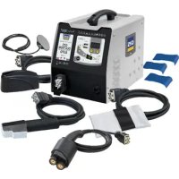
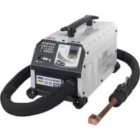
POWERDUCTION 37LG / 39LG / 50LG
INSTRUCTIONS DE SÉCURITÉ
natural_image
Line drawing of a portable industrial machine with wheels and control panel (no text or symbols)39LG
natural_image
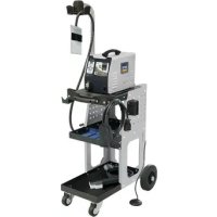
Line drawing of a dual-wheeled industrial machine with wheels and a vertical-mounted sensor (no text or symbols)37LG (si option chariot / if trolley option)
natural_image
Technical line drawing of a mechanical device with wheels and control panel (no text or symbols)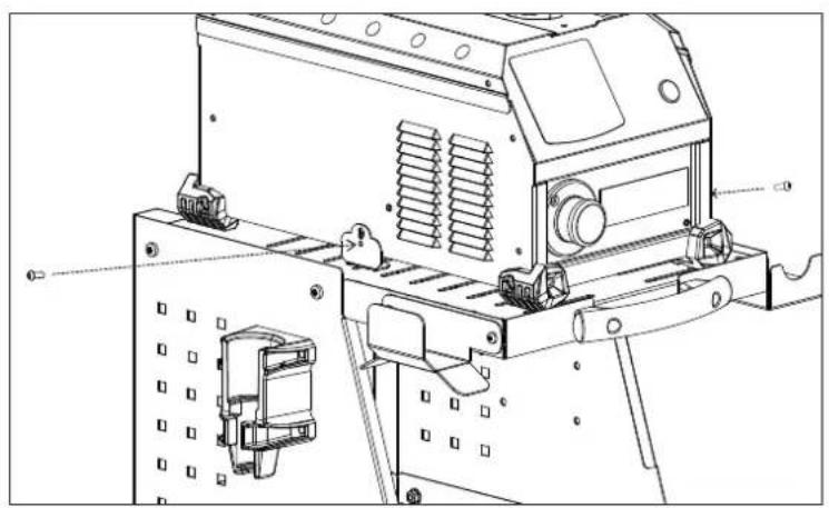
natural_image
Technical line drawing of an electronic device with mounting bracket and internal components (no text or symbols)MISE EN EAU DU RÉSERVOIR / IMPOUNDMENT OF THE RESERVOIR / BEWÄSSERUNG DES SPEICHERS / RIEGO DEL EMBALSE / ПОЛИВ ВОДОХРАНИЛИЩА / BEWATERING VAN HET RESERVOIR / IRRIGAZIONE DEL SERBATOIO
37LG
39LG
50LG
I
II
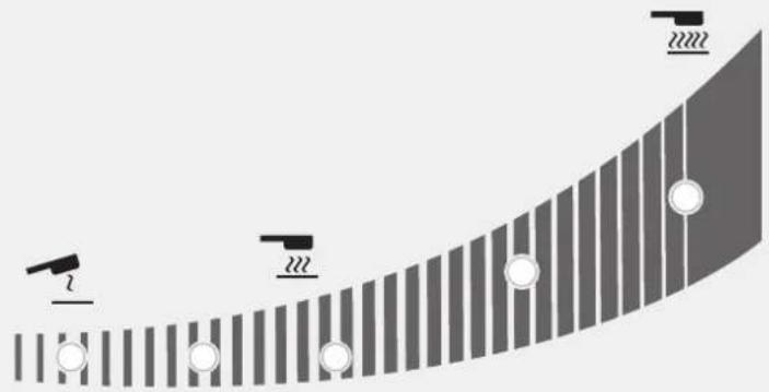
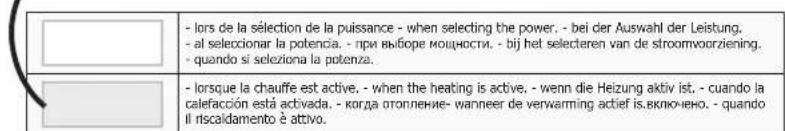
Réaction des témoins lumineux / Reaction of the indicator lights / Reaktion der Kontrollleuchten / Reacción de las luces indicadoras / Peakция индикаторных ламп / Reactie van de indicatielampjes / Reazione delle spie luminose
natural_image
Diagram showing a curved surface with vertical stripes and circular markers, no text or symbols present| État du voyant / Indicator status / Indikatorstatus / Estado del indicador / Состояние индикатора / Indicatorstatus / Stato dell'indicatore | |
| Allumé / Light on / Licht an / Luz encendida / Освещать / Oplichten / Luce accesa | |
| Clignote lentement / Flashing slowly / Blinkt langsam / Parpadea lentamente / Мигания медленно / Knippert langzaam / Lampeggia lentamente | |
| Clignote rapidement / Flashing quickly / Blinkt schnell / Parpadea rápidamente / Мгновенно вспыхивает / knippert snel / Lampeggia rapidamente | |
| Éteint / Off / Aus / Apagado / Выключен / Uit / Spento | |
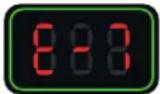
| % | Puissance (W) / Power (W) / Leistung (W) / Potencia (W) / Мощность (W) / Vermogen (W) / Potenza (W) | ||||||
| 37LG 39LG | 50LG | 2 | 222 | 22222 | 22222 | ||
| 10 800 W | 1 kW | ☀️ | ☀️ | ☀️ | ☀️ | ||
| ☀️ | ☀️ | ☀️ | ☀️ | ||||
| 20 1 kW | 1,5 kW | ☀️ | ☀️ | ☀️ | ☀️ | ||
| ☀️ | ☀️ | ☀️ | ☀️ | ||||
| 30 1,25 kW | 2 kW | ☀️ | ☀️ | ☀️ | ☀️ | ||
| ☀️ | ☀️ | ☀️ | ☀️ | ||||
| 40 1,5 kW | 2,5 kW | ☀️ | ☀️ | ☀️ | ☀️ | ||
| ☀️ | ☀️ | ☀️ | ☀️ | ||||
| 50 1,75 kW | 3 kW | ☀️ | ☀️ | ☀️ | ☀️ | ||
| ☀️ | ☀️ | ☀️ | ☀️ | ||||
| 60 2 kW | 3,5 kW | ☀️ | ☀️ | ☀️ | ☀️ | ||
| ☀️ | ☀️ | ☀️ | ☀️ | ||||
| 70 2,5 kW | 4 kW | ☀️ | ☀️ | ☀️ | ☀️ | ||
| ☀️ | ☀️ | ☀️ | ☀️ | ||||
| 80 3 kW | 4,5 kW | ☀️ | ☀️ | ☀️ | ☀️ | ||
| ☀️ | ☀️ | ☀️ | ☀️ | ||||
| 90 3,5 kW | 5 kW | ☀️ | ☀️ | ☀️ | ☀️ | ||
| ☀️ | ☀️ | ☀️ | ☀️ | ||||
| 100 3,7 kW | 5,2 kW | ☀️ | ☀️ | ☀️ | ☀️ | ||
| ☀️ | ☀️ | ☀️ | ☀️ | ||||
| Hi -- 3.7 kW | 5,2 kW | ☀️ | ☀️ | ☀️ | ☀️ | ||
| ☀️ | ☀️ | ☀️ | ☀️ | ||||
IDENTIFICATION DU PRODUIT
SPÉCIFICATIONS DU PRODUIT
natural_image
Hand interacting with a black button labeled '←' and a green circle highlighting the button (no text or symbols present)natural_image
Close-up of a black mechanical component with a cylindrical shaft and circular end caps (no visible text or symbols)Couple de serrage max = 7 Nm
natural_image
Close-up of a mechanical device with a lever and mounting bracket (no visible text or symbols)natural_image
Technical line drawing of a mechanical device with pipes and a base, no visible text or symbols39 LG 50 LG
natural_image
Technical line drawing of a mechanical device with fan, wheels, and internal grid structure (no text or symbols)natural_image
Illustration of a portable electronic device with ventilation grilles and control knobs (no text or symbols visible)37 LG
CONDITIONS DE GARANTIE
This manual contains safety and operating instructions, to be followed for your safety. Please read it carefully before using the device for the first time and keep it in a safe place for future reference. Read and understand the following safety recommendations before using or servicing the unit. Any change or servicing that is not specified in the instruction manual must not be undertaken. The manufacturer is not liable for any injury or damage caused due to non-compliance with the instructions featured in this manual. If there is any issue or uncertainty, please consult a qualified individual to operate the equipment correctly. This machine may only be used to heat ferrous materials within the limits indicated on the equipment and manual. The operator must observe the safety precautions. In case of inadequate or unsafe use, the manufacturer cannot be held liable for damage or injury. Any other uses not specified in this manual is forbidden, and possibly dangerous. The product is semi automatic and requires the presence of an operator.
This unit can be used by children aged 8 or over and by people with reduced physical, sensory or mental capabilities or lack of experience or knowledge, if they are properly monitored or if instructions for using the equipment safely have been read and risks made aware of. Children must not play with the product. Cleaning and maintenance should not be performed by an unsupervised child.
Do not use the charger if the mains cable or plug is damaged.
Do not cover the device.
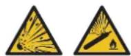
Fire and explosion risks!
- Do not use the device in an explosive atmosphere.
- Keep gas cannisters or other pressurised gas containers away from the induction heating machine.
Warning, heat and flame risk.
- Do not overheat parts and adhesives.
- Be wary of fire, keep a fire extinguisher is in the vicinity.
- Do not position the machine on, or near flammable surfaces.
- Do not position the machine near flammable materials.
Warning ! Very hot surface. Risk of burns.
- The parts and pieces that have just been heated are hot and may cause burns when manipulated.
- Do not touch any hot parts with your hands.
- Wait for the parts and pieces to cool down before handling them.
- Check that jewellery (such as wedding rings) or other metal pieces do not get close to the induction heating machine or the inductor when switched on.
- Remove any jewellery or any metal object from yourself before using this machine
- People with metal implants should not use this machine.

- In case of burns, rinse with water abundantly and see a medical doctor as soon as possible.
Dangerosity of the gas fumes
- Keep the head away from the fumes, do not inhale.
- If working inside, ventilate the area or use a fume extractor to evacuate the gases and fumes.
- Induction heating of certain materials such as adhesives and flux can generate fumes and gases. Breathing these fumes and gases can be dangerous for your health. For example, heating urethane generates a gas: hydrogen cyanide, potentially mortal for humans.
- If the ventilation is insufficient, use an approved respiratory unit.
- Read the safety data sheets (MSDS) and the manufacturer's instructions for adhesives, flux, metals, consumables, coatings, cleaning agents, corrosives, and paint strippers.
- Do not use the heater on parts being degreased or sprayed. The heat might react with fumes and generate highly toxic gases.
- Work in a confined area only if it's well ventilated, or use an approved respiratory/filtration unit. Make sure that a qualified person is around to watch over you. The fumes and gases released while heating can replace oxygen or air, causing accidents or death. Check the quality of the air you're breathing
- Do not overheat metals, such as galvanised steel, covered with lead or cadmium, unless the coating is removed from the surface before it's heated, that the area is well ventilated, and if needed, use an approved filtration/respiratory unit.. Foundry pieces and all metals containing such elements may generate toxic fumes if overheated.
- Check the MSDS for temperature related details.

Warning, electrical danger
Warning ! Major magnetic field. People wearing active or passive implants must be informed.
No further protective steps are required when the machine is used on its own. Further restrictions and/or protective measures may be necessary in other cases.
After maintenance, the magnetic field levels must be checked before the machine is used again.
When switched on, never put the inductor near the head or vital organs.
Caution: Danger of optical radiation when the heated metal elements reach fusion.
People wearing pacemakers are advised to not come close to the machine. Risk of disruption of pacemaker operations when close to the machine.
Consult a doctor before getting close to induction heaters.


Risk of metal or adhesive projections
- Wear approved protective goggles with lateral protections, or protect the whole face with a screen.
- Wear protective clothes.
- Wear gloves.
Do not obstruct the machine's air intake, which facilitates air circulation. Check the installation chapter before using the device.
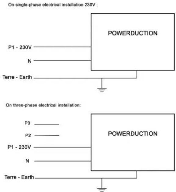
Connection:
- This machine must be connected to an earthed socket.
- These Class A devices are not intended to be used on a residential site where the electric current is supplied by the public network, with a low voltage power supply. There may be potential difficulties in ensuring electromagnetic compatibility on these sites, because of the interferences, as well as radio frequencies.
This hardware is compliant with the IEC 61000-3-12.
This equipment complies with the IEC 61000-3-11.
Maintenance:
- If the power cable is damaged, it must be replaced by the manufacturer, its after sales service or an equally qualified person to prevent danger.
- 'Warning! Always disconnect from the mains before performing maintenance on the device.
• High Voltage and Currents inside the machine. - If the internal fuse is melted, it must be replaced by the manufacturer (GYS' dedicated sales service) or by an equally qualified person to prevent any accidents.
- Remove the casing on a regular basis, to remove any excess dust. Take this opportunity to have the electrical connections checked by a qualified person, with an insulated tool.
- Do not use solvents or any agressive cleaning products.
- Clean the device's surfaces with a dry cloth.
Regulations:
- Device complies with europeans directives.
- The certificate of compliance is available on our website.
- EAC Conformity marking (Eurasian Economic Community).
- Equipment in compliance with British requirements. The British Declaration of Conformity is available on our website (see home page).
- Equipment in conformity with Moroccan standards.
- The declaration C_ (CMIM) of conformity is available on our website (see cover page).
Waste management:
This product should be disposed of at an appropriate recycling facility. Do not throw away in a domestic bin.

TRIMAN symbol
«This product should be recycled appropriately».
PRODUCT IDENTIFICATION
At the back of the product, there is an identification plate on which the CE marking is affixed:
- Name and address of the manufacturer
• Date of manufacture - Model
- Product Type
- Operating Voltage
This data must be specified for each maintenance intervention, or if spare parts are requested.
PRODUCT SPECIFICATIONS
| 37LG 39LG 50LG | ||||
| Rated input voltage 165 V - 265 V | ||||
| Rated frequency 50 Hz - 60Hz | ||||
| Number of conductors 1 Phase + | Ground | |||
| Rated input current 21.2 - 13.2 A | 25 - 20 A | |||
| Rated input power 3 700 W 3 700 | W 5 200 W | |||
| Processing frequency | 15-30 kHz, microprocessor controlled. | 20-60 kHz, microprocessor controlled. | ||
| Rated output power | 1 800 W | 1 800 W 2 800 W | ||
| Length of power cable 2 m | 6 m | 8 m | ||
| Length of lance | 2 m | 3 m | 3 m | |
| Tank capacity | 1,5 litres | 7 litres | ||
| Coolant | Special welding liquid coolant 2 l (ref. 082212) | Special welding liquid coolant 5 l (ref. 062511) | Special welding liquid coolant 10 l (ref. 052246) | |
| Protection class | IP 21 | |||
| Minimum dimensions generator set | 4,5 kVA | 6,5 kVA | ||
| Weight (with accessories + liquid) | 15 kg | 50 kg | 70 kg | |
| Dimensions | 45 x 28,5 x 25 cm | 53 x 70 x 37 cm | 88 x 59 x 59 cm | |
| Internal fuse | - | T4 A - 250 VAC - 5x20 | T4 A - 250 VAC - 5x20 | |
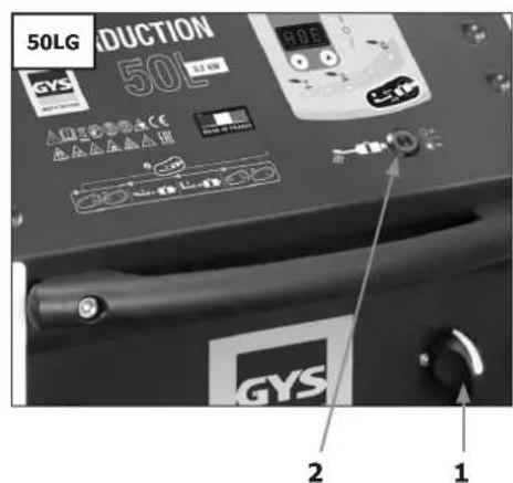
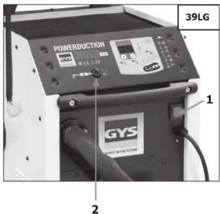
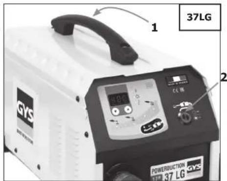
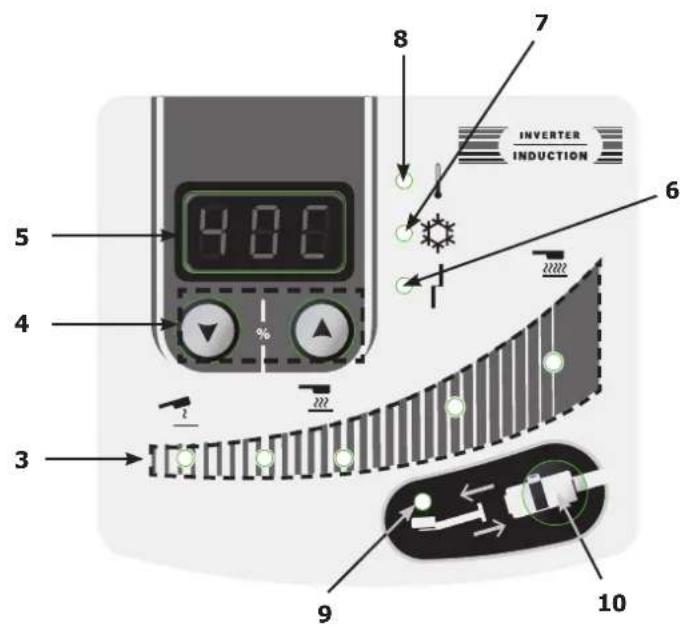
DESCRIPTION OF THE MACHINE (FIG I, II & III)
| 1 | Heat authorisation illuminated button |
| 2 | Main switch |
| 3 | Heating power indicator (1 kW – 5 kW). |
| 4 | Heating power settings or temperature unit button |
| 5 | Cooling liquid temperature |
| 6 | Inductor or machine fault indicator |
| 7 | Cooling circuit warning alarm indicator |
| 8 | Machine or cooling circuit thermal protection indicator |
| 9 | Inductor change indicator |
| 10 | Inductor change mode activation button |
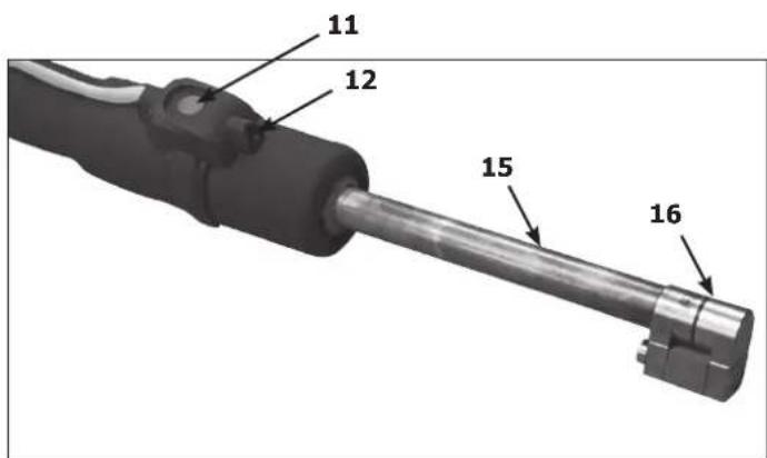
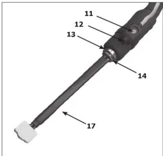
| 11 | Lance button : start the heat |
| 12 | LED worklight (illuminates the heating point) |
| 13 | Lance attachment. For a 27 mm spanner |
| 14 | Lance attachment. For a 32 mm spanner |
| 15 | Adaptor |
| 16 | Inductor |
| 17 | Complete inductor |
FIRST USE
The POWERDUCTION 50LG is supplied with an 8 m power cable fitted with a 5 poles 32 A 50Hz/60Hz plug. For optimal performance, the machine must be connected to a power supply network with a 32 A protection, and protected according to the applicable standards. The product is supplied with a 32A to 16A adapter. It allows the machine to operate on a 16 A plug with proper protection for short periods e.g. to remove seized bolts (see connection instructions).
The POWERDUCTION 37LG and 39LG are supplied with power cable (37LG : 2 m, 39LG : 6 m) fitted with a 2 poles + earth 16 A 50Hz/60Hz plug.
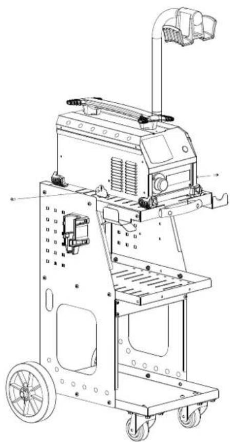
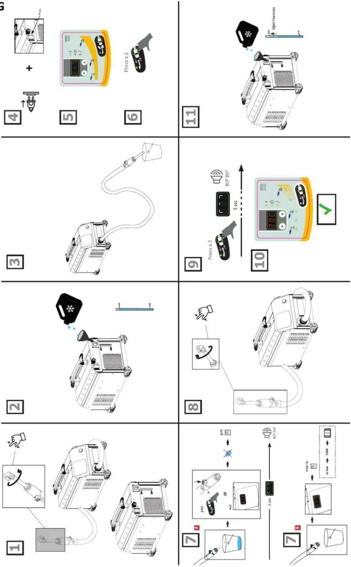
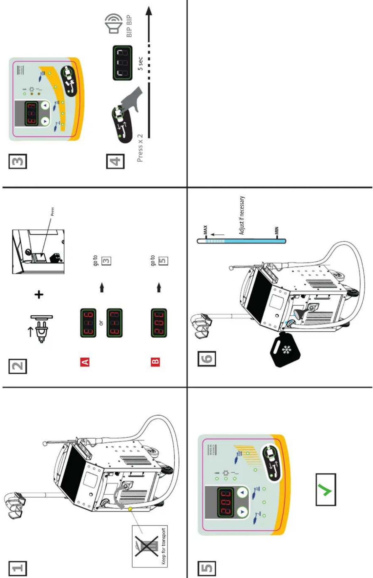
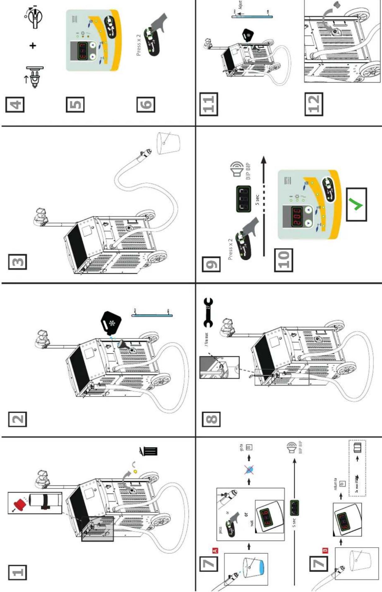
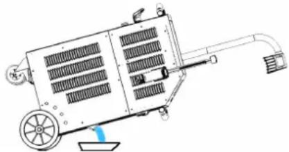
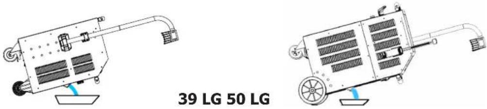
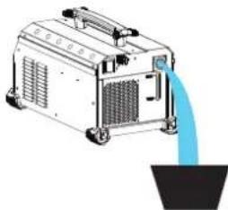
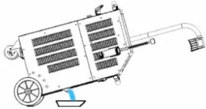
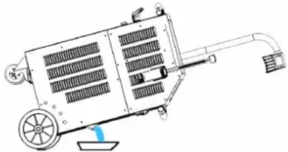
- Once the product is assembled, place the lance on its support (50LG) or so that it points upwards (39 & 37LG). Remove the cap of the lance and the cap of the tank. Remove the torch cap and the tank cap.
- Fill up the tank to the maximum using cooling liquid.
- Place the torch above a bucket.
- Connect the machine to the mains. Switch on the machine (1).
- The machine starts and will systematically display Error 7.
- Press the accessory change button (10) twice. The purge cycle takes 5 seconds (a loading icon should be displayed during it) and a double «beep» sound indicates completion.
- As soon as the liquid is coming out of the torch, stop the torch by pressing the torch button, the accessory change button or the heat authorisation button. Or wait for «E-6» to be displayed. If Error 7 is displayed, start again from step 6 (five times max, see default E-7 explanation).
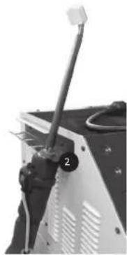
- Screw the inductor on using a maximum coupling of 7Nm.
- Press the accessory change button (10) twice. The purge cycle takes 5 seconds (a loading icon should be displayed during it) and a double «beep» sound indicates completion.
- The temperature of the cooling liquid and the power instruction are displayed.
- Top up the tank with cooling liquid if required.
- Close the tank using the cap supplied with the accessories. The machine is now ready to be used.
Solving fault E-7
If the issue remains, check that the pump is working correctly or that the pipe is not blocked.
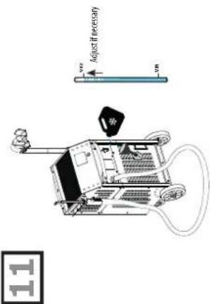
After five unsuccessful purge cycles, it is possible to:
- Stretch the torch above the machine to clear any pocket of water and for the pump to kick in.
- Put the machine at a 30^ angle towards the torch.
- It is possible to blow the torch. Use an air blower and a cloth to keep it water proof and avoid projections.
- Re-attempt one or two cycles after each action.
If the issue remains, check that the pump is working correctly or that the pipe is not blocked.
INSTRUCTIONS
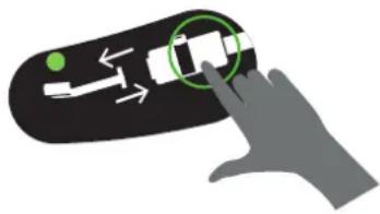
- Set the main switch (1) to ON.
The machine initialises in 2 seconds. - Press the heat authorisation button (2) as described on page 11. The indicator on button (2) and the lance support LED (12) both switch on, indicating that the machine is ready to operate.
- Position the inductor (13) flat on the workpiece (place the open part of the ferrite towards the workpiece).
- Press the button (11) on the lance to start the heating; if necessary move the inductor to heat a larger area. Two indicators indicate that the heating is active:
- The brightness of the LED illuminating the inductor (12) decreases*.
- The minimum power indicator light on the heating power indicator (3) flashes quickly (in HI mode both min & max lights flash).
It is possible to change the rated power during the heating.

The heating set point can be set to Hi. The power is identical to the 100% mode but the Powerduction behaves differently:
- At 100%: he wears the part red and maintains the right power for a few seconds before slowly reaching its maximum power.
- In Hi mode: it rises to its maximum power regardless of the condition of the room to be heated. Remain very vigilant, the heating is strong and fast and may damage the part without a control of this mode.
The display provides a continuous update of the cooling liquid temperature (max 60°C/140°F).
- During the powering up phase, the pump and the cooling fan activate for a few seconds, to check that they are working properly.
- After the heating stops, let the cooling circuit operate to cool down the inductor, before switching off the machine.
- To modify the cooling liquid temperature unit, press and hold both settings buttons (4) until the desired unit is displayed (" -F-" = Farenheit / " -C- " = Celsius). Release the buttons, the change is saved and in effect.

The machine has been designed to minimise the risks due to electromagnetic fields. Some residual risks persist and it is recommended to observe a security distance between the inductor and the operator's head/torso.
Heat on standby
For security reasons, the product deactivates the heat authorisation after 5 minutes of inactivity. The heat authorisation button indicator and the lance support LED both switch off.
To reactivate the machine, press the heat authorisation button (2) or press and hold the lance button (11) for 1 second.
This feature is disabled after 20 minutes of inactivity.
It allows the user to stay in a working position without the need to reach for the machine.
INDUCTOR PRESERVATION
The heated metal radiates heat on to the inductor at the square of the temperature to which it is heated. The inductor is therefore highly exposed. When the metal is dark red, the temperature is below 850^ C. If it turns bright red/orange, the temperature exceeds 1000^ C. If it turns white, the temperature exceeds 1200^ C (the chart below is available in colour on the website manual).
600 °C 900 °C 1300 °C
To preserve the inductor and extend its life, it is necessary to keep the temperature around 850^ C as much as possible and avoid prolonged use.
The ferrite included in the inductor has a higher coefficient of expansion than its mechanical support. Excessive heating of the inductor causes distortion to the ferrite. It is up to the user to avoid this excessive heating.

Therefore, inductors are consumables to which the warranty does not apply.
WARNING LIGHTS
- The indicator 6 signals a machine/inductor fault.
- The indicator 7 signals a cooling circuit liquid flow fault.
- The indicator 8 signals a thermal protection of the power block or the excessive temperature of the cooling liquid.
Wait for the indicator to switch off and the machine is ready to operate.
The display 5 displays the fault code :
| Fault code | Cause | |
| E - 1 Heat | authorisation button (2) is stuck. In short-circuit or mechanically blocked. | |
| E - 2 Lance | button (11) is stuck. In short-circuit or mechanically blocked. | |
| E - 3 Keypad | buttons are stuck (9) and (11). In short-circuit or mechanically blocked. | |
| E - 4* | Inductor intensity is too high or not compatible. | Faulty lance or inductor in short circuit. |
| E - 5* Inductor intensity is too low. | Inductor is not screwed properly or faulty lance. | |
| E - 6 | Flow is too high >6 l/min. | Pierced hose or missing inductor. |
| E - 7 Flow too low <4 l/min. | Hose is pinched or obstructed, the pump does not operate. | |
| E - 8* Internal fault. | Disconnected flat command cable. | |
| E - 9 | Voltage network fault. | The network voltage is too low under 165 V. |
| --- | Overvoltage fault. | Voltage above 300 V. sector. |
| *For E-4, E-5 and E-8 faults, restart the unit to correct the fault. | ||
| Fault code E5Inductor screwing problem :(check screwing, be careful not to overtighten!) | Fault code E6Flow rate fault refer to pages 10, 11, 12, 16 | Fault code E7Flow rate fault refer to pages 10, 11, 12, 16 |
 |  |  |
NB : In the event of a warning alarm, the machine does not work.
The machine is fitted with several protection systems against electrical overcharge and cooling faults. The thermal protection of the inductor is mainly used when heating stainless steel, copper or aluminium parts. To reactivate the machine, simply wait for the cooling phase to end. For other protections, switch off the machine using the main switch and switch it back on.
For fault alarms E-6 and E-7, check that there is no leak or an obstructed/broken hose, that the pump is not blocked or deactivated and that there is enough cooling liquid in the tank. If the problem appears to have been rectified, press the «inductor change» button twice (10). The cooling circuit is performing a purge cycle. It is ready to operate.
Press x 2
natural_image
Hand interacting with a device on a black surface, showing a green circular icon highlighting a button (no text or symbols present)TIME DELAY MODE\*
The "Timing" function allows you to control the heating time of the Powerduction.
The time is adjustable from 1 to 30 s.* (Time adjustable from 1 to 120 s from Soft V6.50 version)*.
To enter this mode:
- Press the heating authorization button (2). Its indicator light comes on.
- Then press both power adjustment buttons (4) simultaneously. The display shows "SEC" then "T 00" or "SEC" then "ON" if a time has already been set.
- The power setting buttons (4) become time setting buttons. Change the setpoint from time to time as desired.
⚠️ If the time value has not been changed beyond 3 seconds and still shows "T 00", the Powerduction returns to normal mode.
Use in "Timer" mode:
Once the time setpoint has been selected, the product is ready for operation. The lighting LED (12) is lit.
- Press the lance button (11). The intensity of the LED (12) decreases to indicate that the heating is active.
- The heating stops at the end of the time limit. As long as the lance button (11) is pressed, the LED (12) and the heating enable button (2) flash to warn that the power is off. Adjust the time setpoint if necessary.
- Press the lance button (11) for a new heating cycle.
Exit the "Timer" mode
The mode remains active at all times, even when the Powerduction is switched off and then on again.
- To exit the mode, set the time setpoint on or press both power control buttons (4) simultaneously. The Powerduction returns to normal operating mode. The display shows "SEC" then "OFF".
Special feature of the power setting in this mode
As explained, in normal use mode the setting buttons allow you to change the power while in this mode they change the time setpoint. To change the power without leaving the mode:
- Press the heating authorization button (2). Its green light goes out.
- The setting buttons (4) allow you to change the power. Adjust the power.
- Press button (2) again. Its indicator light comes on again. The setting buttons (4) become the time setting again.
natural_image
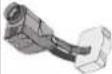
Close-up of a mechanical component with no visible text or symbolsTightening torque max = 7N
This mode is accessible only if the heating isn't activated (green button switched off).
- Press the button (10), the pump stops and the LED (9) switches on.
- Place the lance on its supports and put the cable on the ground (to prevent loss of cooling liquid).
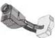
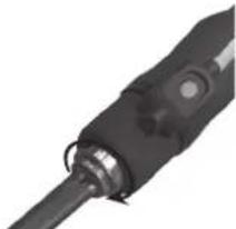
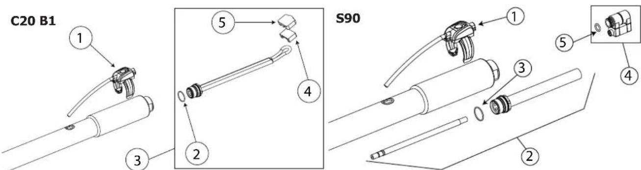
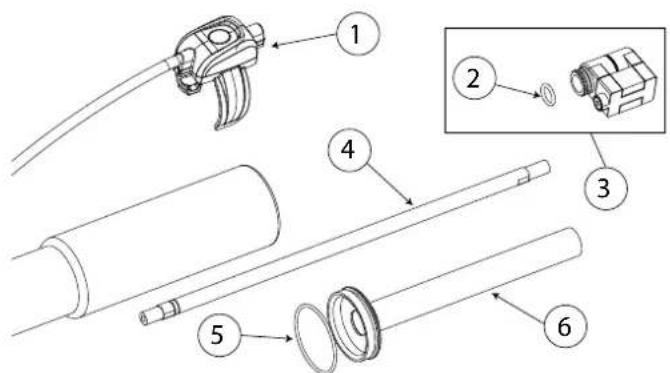
- If the Powerduction is equipped with a complete inductor, unscrew it with the key of 27 (supplied with the product). If it is equipped with a simple inductor, unscrew it manually and then unscrew the adapter if necessary.

The Powerduction 37LG is equipped with a fixed connection S, it cannot be unscrewed.
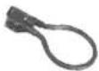
natural_image
Close-up of a mechanical component with a cable and pin, no visible text or symbols- Depending on the choice of the new inductor: screw on a complete inductor using the wrench supplied or screw on the appropriate adapter (7 N.m max) and then screw on the new inductor manually.
- Press the button again (10).
The pump activates. For 5 seconds, the LEDs display a wait pattern.
If the flow is correct, the machine emits a double «BEEP» and the product is ready to operate.
Otherwise a fault is displayed (refer to the fault code table).
Inductors and Adapters
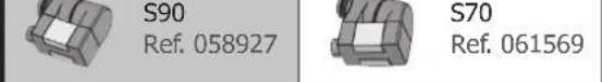
The Powerduction 37LG is equipped with a fixed connection S and is supplied as standard with the S90 or S180/B3W inductor. (depending on model).
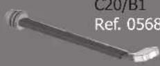
The Powerduction 39LG and 50LG are delivered with complete C20/B1 inductor or 28S + S90 adaptor.
(depending on model).
The other accessories are optional, they extend the heating possibilities to a wide range of applications.
Discover the complete range

Complete inductors Ada
| C20/B1 Ref. 056862 | 28S Ref. 064485 | 28L Ref. 064492 | ||
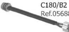
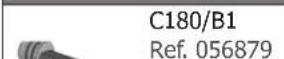
| C180/B1 Ref. 056879 | Inductors | |||
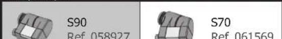
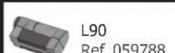
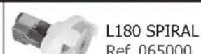
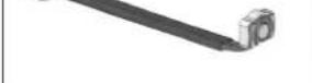
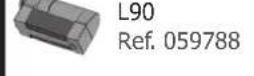
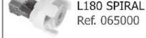
| S90 Ref. 058927 | S70 Ref. 061569 | L90 Ref. 059788 | L180 SPIRAL Ref. 065000 | |
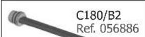
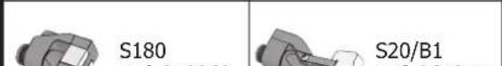
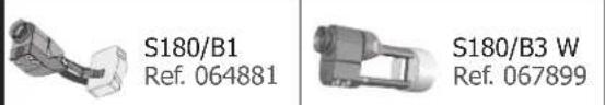
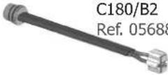
| C180/B2 Ref.056886 | S180 Ref. 059269 | S20/B1 Ref. 064874 | L70 Ref. 059771 | L20/B4 Ref. 067882 |
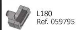
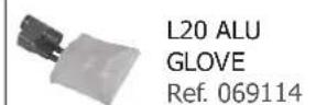
| S180/B1 Ref. 064881 | S180/B3 W Ref. 067899 | L180 Ref. 059795 | L20 ALU GLOVE Ref. 069114 | |
| L180 D80 Ref. 069121 | ||||
This mode is only available if the heat is not activated (green switch is off).
- Push the button (10), the pump stops and the LED (9) lights up.
- Position the torch on its support and place the cable on the floor (to avoid liquid spillage).
- Unscrew the accessory using key 27 (supplied with the machine).
- Push and hold the heat authorisation button (2) for 3 seconds until it lights up.
- Place the torch button above a bucket with a capacity of 10l minimum.
- Push the torch button (11). The pump activates until the debit falls under 1l / minute or for 2 minutes. The machine displays the debit in decilitre per minute.
- To interrupt the pump during the cycle, push any button.
-
To empty the cooling circuit, use a blower to blow air (30PSI) at the end of the torch until you can hear the air flowing or projections of liquid coming out of the tank.
-
To empty the tank, use a pump or push the machine forward in order to have it at an angle.
- To top up the cooling liquid, refer to the installation instructions.
It is advisable to change the coolant every year if you are using it intensively, otherwise the Powerduction lance will deteriorate. Prefer the use of the special welding coolant offered with Powerduction (see § Maintenance).
This mode is only available if the heat is not activated (green switch is off).
- Place the inductor, making sure it points upwards. Place the cable on the floor to avoid liquid spillage.
- Unscrew the accessory manually.
- Place the torch button above a bucket with a capacity of 10l minimum.
- To empty the tank, place the product button above a bucket with a capacity of 10l minimum and lean the product on the back.
natural_image
Illustration of a portable air purifier with blue liquid being poured into it (no text or symbols)37 LG
It is advisable to change the coolant every year if you are using it intensively, otherwise the Powerduction lance will deteriorate.
COOLING CIRCUIT AND «FORCED COOLING» MODE (39LG & 50LG)
To prevent the cooling liquid's temperature from rising, the cooling fan starts, in any event, when the liquid's temperature reaches 35^ (95°F). As soon as the temperature goes below that, the cooling fan switches off.
During long periods of use, the POWERDUCTION has a forced cooling mode. To activate it :
- Set the main switch (1) to ON.
The machine initialises in 2 seconds.
-
Press the activation button (2) as described on page 5. The indicator on button (2) and the lance support LED (12) both switch on, indicating that the machine is ready to operate.
-
Hold (>3 seconds) the button (10). The « Forced cooling» mode is activated.
The cooling fan then starts automatically. The cooling fan will be audible and the «Fan ON» message will appear on the display.
To stop the «Forced cooling», press the activation button to stop the heating or hold the button (10) again. The message «Fan OFF» is displayed.
MAINTENANCE
General recommendations
- It is advisable to change the coolant every 2 years at the latest, regardless of use, otherwise the POWERDUCTION lance may deteriorate.
- Prefer the use of the special welding coolant offered with Powerduction. Do not use automotive fluids, only coolants with low electrical conductivity.
- Prefer the use of the special welding coolant offered with Powerduction. Do not use automotive fluids, only coolants with low electrical conductivity.
Recommended tightening torque for power screws
| Screw dimensions M5 M6 M8 M10 hose clamp | Gaz 1/43/8 Gaz | M28 M32 | Inductor 16/22 | ||||||
| Material | steel | steel | brass | brass | copper | copper | copper | ||
| Couple | 4 Nm | 6 Nm | 7 Nm | 7 Nm | 2,5 Nm | 4 Nm | 7 Nm max | 7 Nm max | by hand, 4 Nm max |
- It is essential that the maintenance of the product is performed by qualified, authorised staff, that is fully aware of the recommendations outlined in this manual.
- Never clean, lubricate or perform maintenance on the product when it's being used.
- Before any maintenance work, set the On / Off switch to « 0 » to switch off the machine, .then disconnect it it from the mains power supply to prevent any electrical shock or other risks resulting from improper handling.
- Do not wear rings, watches, jewellery, hanging clothes (e.g. ties), torn clothes, scarves, unbuttoned or unzipped jackets, or anything that could get caught during the operation of the machine
- Rather wear clothing specifically designed for the prevention of accidents, such as: non-slip shoes, anti-noise helmets, protective goggles, safety shoes, etc...
- Never use petrol or flammable solvents to clean the product. Prefer the use of water and, if necessary, non toxic commercial solvents.
• After maintenance, always put and secure the metal covers back on, before switching the machine on. - The ferrite on inducer can be replaced if damaged.
To replace it, you must :
- Remove the protection,
- Remove the ferrite on copper with a heat gun to facilitate the removal of the resin,
- Clean copper,
- Glue the ferrite with the specific resin,
- Reposition the ferrite with its protection,
- Waiting for the complete setting of the adhesive before using the inductor.
ACCESSORIES
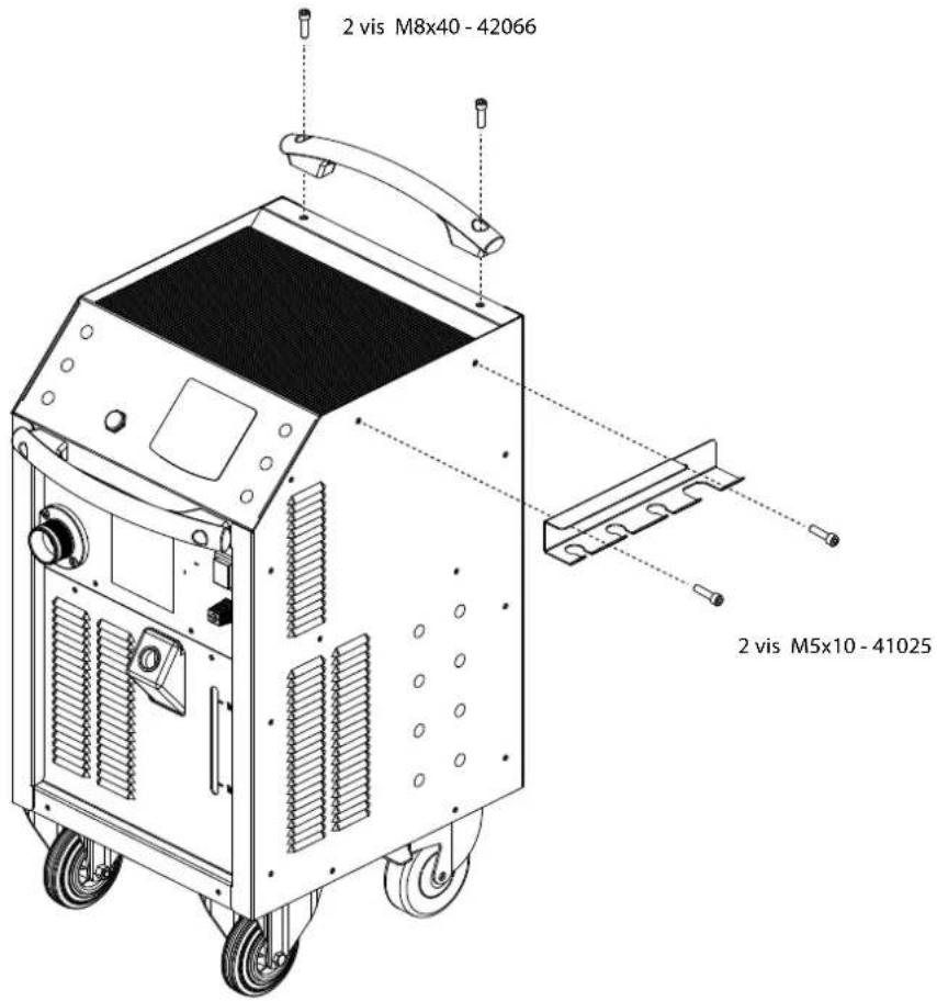
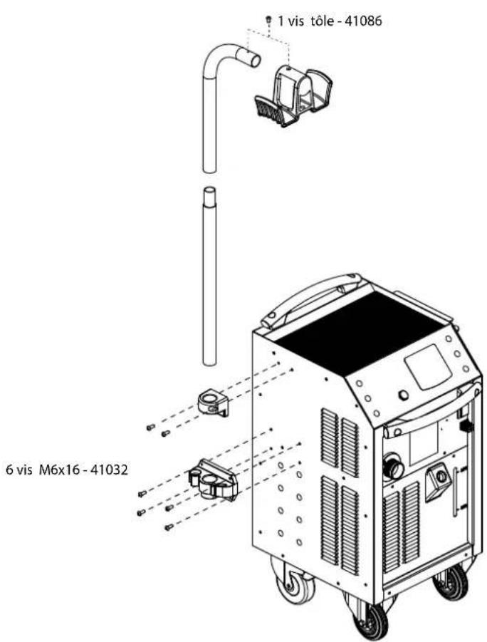
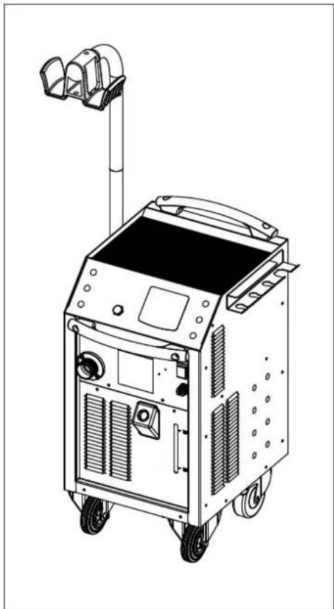
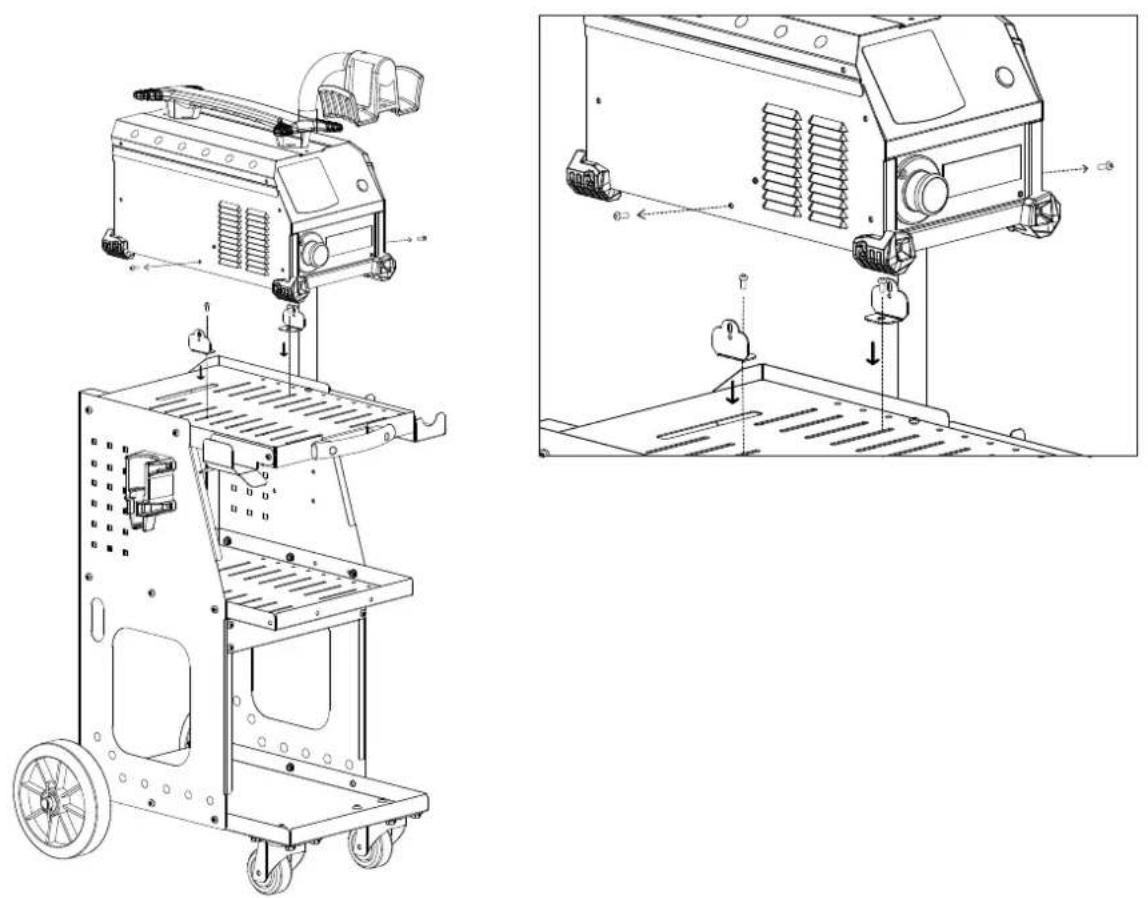
| 39LG - 50LG 37LG | ||
| Gallows - Cable carrier | ||
052284 |  2 fixing brackets(if choice trolley option) 2 fixing brackets(if choice trolley option) | |
| -- | ||
OPTIONS
| 39LG - 50LG 37LG | |||
| Ferrite Protection UNIVERSAL 800 + Gallows | |||
 053823 053823 |  056909 056909 | 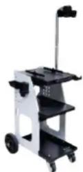 051331 + 052284 051331 + 052284 | |
 053458 053458 |  056916 056916 | ||
| Glue kit for inductor | |||
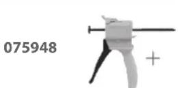 |  | 054851Bi-componentpower epoxy glue50 ml | |
051331 + 052284
Special welding liquid coolant
| 2110151 | ||
082212 052246 |  | 062511 |
Preventive maintenance
Meticulous inspections should be carried out at regular intervals to quickly detect and eliminate faults, so they will not cause damage to the device.

Prior to each use of the POWERDUCTION, check the unit's security systems and any anomalies that may hinder the proper operation of the device. Perform daily checks to identify signs of wear.

The operational safety of the product can only be guaranteed if the repairs are carried out using original spare parts, and if the maintenance instructions are followed.
After each use and once the product is switched off, it should be cleaned immediately to remove any dust or dirt that may impair cooling efficiency, affect the proper functioning of the product and reduce its lifespan.
Before each use, check the good operation of the main systems, security systems, and all the electrical cables connection.

Perform periodic visual inspections to verify that there are no cooling liquid leaks, and check that the vents are not obstructed.
ELECTRICAL CONNECTIONS
The product is designed to operate on a single phase power supply from 165 V to 265 V,
WARRANTY
The warranty covers faulty workmanship for 2 years from the date of purchase (parts and labour).
The warranty does not cover:
- Transit damage.
- Normal wear of parts (eg. : cables, clamps, etc..).
- Damages due to misuse (power supply error, dropping of equipment, disassembling).
- Environment related failures (pollution, rust, dust).
- Inductors and removable ferrites that are consumables.
- Use of unspecified coolant.
In case of failure, return the unit to your distributor together with:
- The proof of purchase (receipt etc ...)
- A description of the fault reported
SICHERHEITSHINWEISE
natural_image
Hand interacting with a device icon, showing a green dot and directional arrows (no text or symbols)natural_image
Close-up of a black electrical plug with a metallic connector and circular button (no visible text or symbols)Max. Drehmoment = 7 Nm
natural_image
Close-up of a mechanical device with a lever and cable (no visible text or symbols)natural_image
Diagram of a mechanical device with pipes and a bowl, no visible text or symbols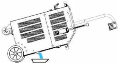
natural_image
Technical line drawing of a mechanical device with fan, wheels, and wiring (no text or symbols)39 LG 50 LG
natural_image
Illustration of a mechanical device emitting blue liquid from a container (no text or symbols)37 LG
natural_image
Hand interacting with a device icon, showing directional arrows and a green circle highlighting a specific point (no text or symbols present)MODO "TEMPORIZADOR"\*
natural_image
Close-up of a mechanical component with a curved arrow indicating rotational motion (no text or symbols)natural_image
Close-up of a mechanical component with a rod inserted, no visible text or symbols| Descubra la gama completa |  | |||
| Inductores completos Adaptadores | ||||
| C20/B1Ref. 056862 | 28SRef. 064485 | 28LRef. 064492 | ||
| C180/B1Ref. 056879 | Inductores | |||
| S90Ref. 058927 | S70Ref. 061569 | L90Ref. 059788 | L180 SPIRALRef. 065000 | |
| C180/B2Ref.056886 | S180Ref. 059269 | S20/B1Ref. 064874 | L70Ref. 059771 | L20/B4Ref. 067882 |
| S180/B1Ref. 064881 | S180/B3 WRef. 067899 | L180Ref. 059795 | L20 ALUGLOVERef. 069114 | |
| L180 D80Ref. 069121 | ||||
| Inductores completos Adaptadores | |||||||
 62 62 | 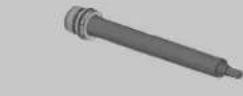 28Re 28Re 35 35 | 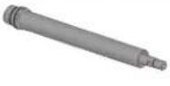 | 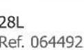 | ||||
C180/B1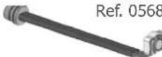 79 79 | Inductores | ||||||
 S90Ref. 058927 S90Ref. 058927 |  S70Ref. 061569 S70Ref. 061569 |  L90Ref. 059788 L90Ref. 059788 | 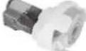 L180 SPIRALRef. 065000 L180 SPIRALRef. 065000 | ||||
 36 36 |  S180Ref. 059269 S180Ref. 059269 | 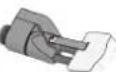 S20/B1Ref. 064874 S20/B1Ref. 064874 |  L70Ref. 059771 L70Ref. 059771 | 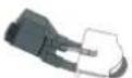 L20/B4Ref. 067882 L20/B4Ref. 067882 | |||
 S180/B1Ref. 064881 S180/B1Ref. 064881 | 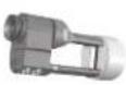 S180/B3 WRef. 067899 S180/B3 WRef. 067899 |  L180Ref. 059795 L180Ref. 059795 | 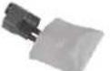 L20 ALUGLOVERef. 069114 L20 ALUGLOVERef. 069114 | ||||
 L180 D80Ref. 069121 L180 D80Ref. 069121 | |||||||
MODO "VACIADO" (39LG & 50LG)
natural_image
Pure diagram of a mechanical device with no text, numbers, or symbols visible39 LG 50 LG
natural_image
Technical line drawing of a mechanical device with wheels and a handle (no text or symbols)natural_image
Illustration of a portable air purifier with blue liquid being poured into it (no text or symbols)37 LG
natural_image
Hand interacting with a device icon, showing directional arrows and a green circle highlighting a button (no text or symbols)natural_image
Close-up of a mechanical component with a cylindrical shaft and circular features, no visible text or symbols.natural_image
Close-up of a mechanical component with a cable inserted, showing no visible text or symbols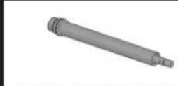
28L Ref. 064492
Индукторы


L180 D80
Ref. 069121
natural_image
Diagram of a mechanical device with cooling fins and a water drop (no text or symbols)39 LG 50 LG
natural_image
Technical line drawing of a mechanical device with fan, wheels, and internal grid structure (no text or symbols)natural_image
Illustration of a mechanical device emitting blue liquid into a container (no text or symbols)37 LG
BESCHRIJVING VAN HET APPARAAT (FIG I, II & III)
natural_image
Hand interacting with a black pad interface, showing a green circular button and directional arrows (no text or symbols)TIJDVERTRAGINGSMODUS\*
natural_image
Close-up of a black mechanical component with a curved arrow indicating rotation (no visible text or symbols)maximumkoppel = 7N
natural_image
Close-up of a mechanical component with a cable inserted, showing no visible text or symbols.| Ontdek het volledige gamma |  | ||||||
| Complete inductoren Adapters | |||||||
C20/B1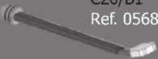 62 62 | 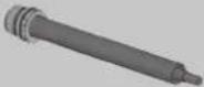 | 28SRef. 064485 | 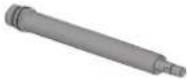 | 28LRef. 064492 | |||
C180/B1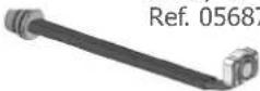 79 79 | Inductoren | ||||||
 | S90Ref. 058927 |  | S70Ref. 061569 |  | L90Ref. 059788 | 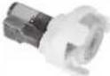 L180 SPIRALRef. 065000 L180 SPIRALRef. 065000 | |
 36 36 |  | S180Ref. 059269 | 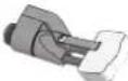 | S20/B1Ref. 064874 |  | L70Ref. 059771 | 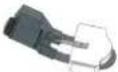 L20/B4Ref. 067882 L20/B4Ref. 067882 |
 | S180/B1Ref. 064881 | 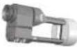 | S180/B3 WRef. 067899 |  | L180Ref. 059795 | 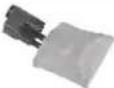 L20 ALUGLOVERef. 069114 L20 ALUGLOVERef. 069114 | |
 L180 D80Ref. 069121 L180 D80Ref. 069121 | |||||||
MODUS «ONDERDELEN VERVANGEN» (SERIGRAFIE VAN HET PRODUCT)
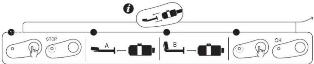
flowchart
graph LR
    A["Start"] --> B["STOP"]
    B --> C["A"]
    C --> D["B"]
    D --> E["B"]
    E --> F["OK"]
    style A fill:#f9f,stroke:#333
    style B fill:#ccf,stroke:#333
    style C fill:#cfc,stroke:#333
    style D fill:#fcc,stroke:#333
    style E fill:#cff,stroke:#333
    style F fill:#ffc,stroke:#333
natural_image
Close-up of a black mechanical component with a metallic end and cylindrical shaft (no visible text or symbols)maximumkoppel = 7N
natural_image
Close-up of a power supply unit with a lever and attached sensor (no visible text or symbols)natural_image
Technical line drawings of two industrial machines labeled 39 LG and 50 LG, showing internal components and wiring (no text or symbols beyond labels)natural_image
Illustration of a portable air purifier with blue liquid flowing from its side, no text or symbols present37 LG
natural_image
Hand interacting with a device icon, showing a green dot and directional arrows (no text or symbols)"MODALITÀ "TIMER"\*
natural_image
Close-up of a mechanical component with a cylindrical shaft and circular end caps (no visible text or symbols)coppia massima = 7N
natural_image
Close-up of a mechanical component with a cable inserted, showing no visible text or symbols.natural_image
Technical line drawing of a mechanical device with pipes and a base, no visible text or symbols39 LG 50 LG

natural_image
Technical line drawing of a mechanical device with wheels and a handle (no text or symbols)natural_image
Illustration of a portable air purifier with blue liquid flowing from its side, no text or symbols present37 LG
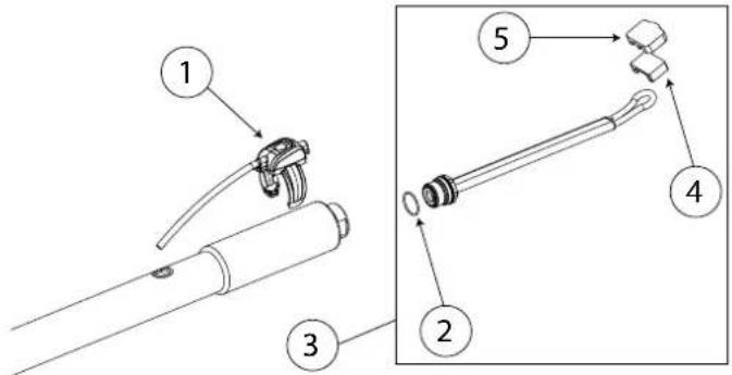
| N° Désignation Réf | ||
| 1 | Axe de roue / Wheel axle / Radachse / Eje de la rueda / Ось колеса / Wielas / Asse delle ruote | 91100ST |
| 2 | Poignée plastique / Plastic handle / Kunststoffgriff / Mango de plástico / Пластиковая ручка / Kunststof handvat / Maniglia in plastica | 56014 |
| 3 Roue / Wheel / Rad / Rueda / Koleco / Wiel / Ruota 71375 | ||
| 4 | Ventilateur / Ventilator / Beatmungsgerät / Ventilador / Вентилятор / Ventilator / Ventilatore | 51021 |
| 5 | Presse étoupe / Cable gland / Kabelverschraubung / Glándula de cable / кабельный ввод / Klier / Pressacavo | 71164 |
| 6 | Enrouleur de Cables - Pinces / Cable Reel - Pliers / Kabeltrommel - Zange / Carrete de cable - Alicates / Кабельный барабан - Клещи / Kabelhaspel - Tang / Avvolgicavo - Pinze | 56131 |
| 7 Pompe / Pump / Pumpe / Bomba / Hacoc / Pomp / Pompa 71746 | ||
| 8 Clavier / Keyboard / Tastatur / Teclado / Клавиатура / Toetsenbord / Tastiera 51967INDX | ||
| 9 | Interrupteur Marche/Arrêt / On/Off switch / Ein/Aus-Schalter / Interruptor de encendido y apagado / Переключатель Вкл/Выкл / Aan/uit-schakelaar / Interruttore On/Off | 51075 |
| 10 | Capteur de débit / Flow sensor / Durchflusssensor / Sensor de flujo / Датчик расхода / Stromingssensor / Sensore di flusso | 81100 |
| 11 | Roue pivotante avec frein / Swivel wheel with brake / Schwenkrad mit Bremse / Rueda giratoria con freno / Шарнирное колесо с тормозом / Zwenkwiel met rem / Ruota girevole con freno | 71360 |
| 12 | Self / Self / Spule / Self / Inductie spoel / Self | 63691 |
| 13 | Transformateur / Transformer / Transformator / Transformador / Трансформатор / Transformator / Trasformatore | 96175 |
| 14 | Circuit alimentation & CEM / Power supply & EMC circuit / Stromversorgung & EMV-Schaltung / Fuente de alimentación y cir-cuito EMC / Источник питания и электромагнитная цепь / Stroomvoorziening & EMC-circuit / Alimentazione e circuito EMC | 97367C |
| 15 | Carte de commande / Control card / Kontrollkarte / Tarjeta de control / Карта управления / Besturingskaart / Scheda di controllo | Si fab < 21.01 : S97788Si fab = 21.01 : Consulter SAVSi fab > 21.01 : 97788C |
| 16 | Bouton lumineux vert / Green illuminated button / Grün beleuchtete Taste / Botón verde iluminado / Зеленая кнопка с подсветкой / Groen verlichte knop / Pulsante verde illuminato / | 51403 |
| 17 | Circuit CEM / EMC circuit / Leistungsfluss-EMV-Schaltung / Circuito de conducción de energía EMC / Электромагнитная цепь электромагнитной совместимости / Elektriciteitsnet EMC-circuit / Circuito EMC a conduzione di potenza | 97472C |
| 18 | Circuit primaire / Primary circuit / Primärer Kreislauf / Circuito primario / Первичный контур / Primair circuit / Circuito pri-mario | 97447C |
| 19 | Circuit adaptation interface clavier / Keyboard interface adaptation circuit / Schaltung zur Anpassung der Tastaturschnittstelle / Circuito de adaptación de la interfaz del teclado / Схема адаптации интерфейса клавиатуры / Toetsenbordinterface aanpassingscircuit / Circuito di adattamento dell'interfaccia della tastiera | 97782C* |
| 20 | Lance / Launch / Starten Sie / Lanzamiento / Заныск / Lancering / Lanciare | 94196 |
| 21 | Cordon secteur / Power cord / Netzkabel / Cable de alimentación / шнур питания / Stroomkabel / Cavo di alimentazione | 21556 |
| 22 | Pied de maintiein potence / Handle foot for gallows / Handgriff-Fuß für Galgen / Pie de mango para la horca / Ручка-ножка для виселицы / Handgreepvoet voor galg / Piedino per forca | 56023 |
| 23 | Maintien haut potence / High gallows support / Hohe Galgenunterstützung / Soporte de la horca alta / Высокая виселица поддержка / Hoge galgsteun / Supporto per forca alta | 56024 |
| 24 | Potence support cable / High gallows support / Kabelhalterung / Soporte del cable / Кронштейн опоры кабеля / Kabelsteun-beugel / Staffa di supporto del cavo | fab050ST |
| 25 | Mat potence / Mat gallows / Matten-Galgen / La horca de esteras / ковровая виселица / Matgalg / Forca di stuoia | 91025ST |
POWERDUCTION 37LG / 39LG / 50LG
| 26 | Support câble pour potence / Cable support for a gallows / Kabelhalterung für einen Galgen / Soporte de cable para una horca / Кабельная опора для виселицы / Кабельная опора для виселицы / Kabelsteun voor een galg / Supporto per cavo per força | 56019 |
| 27 | Condensateur de résonnance / Resonance capacitor / Resonanzkondensator / Condensador de resonancia / Резонансный конденсатор / Resonantiecondensator / Condensatore di risonanza | 52250 |
| 28 | Nappe / Ribbon cable / Flachbandkabel / Cable plano / ленточный кабель / Lint kabel / Cavo a nastro | 63781 |
| 29 | Condenseur à eau / Water-cooled condenser / Wassergekühler Kondensator / Condensador enfriado por agua / Водяной конденсатор / Watergekoelde condensator / Condensatore raffreddato ad acqua | 71777 |
| 30 | Ventilateur / Ventilator / Beatmungsgerät / Ventilador / Вентилятор / Ventilator / Ventilatore | 51004 |
| N° Désignation Réf | ||
| 1 Pompe / Pump / Pumpe / Bomba / Hacoc / Pomp / Pompa 71746 | ||
| 2 | Ventilateur / Ventilator / Beatmungsgerät / Ventilador / Вентилятор / Ventilator / Ventilatore | 51048 |
| 3 | Radiateur à eau 3 rangés / Water radiator 3 rows / Wasserkühler 3 Reihen / Radiador de agua 3 filas / Водяной радиатор 3 ряда / Waterradiator 3 rijen / Radiatore dell'acqua 3 file | 71778 |
| 4 | Ventilateur radiateur / Radiator fan / Heizkörperventilator / Ventilador del radiador / Вентилятор радиатора / Radiatorventilator / Ventola del radiatore | 51014 |
| 5 | Roue pivotante avec frein / Swivel wheel with brake / Schwenkrad mit Bremse / Rueda giratoria con freno / Шарнирное колесо с тормозом / Zwenkwiel met rem / Ruota girevole con freno | 71360 |
| 6 | Transformateur / Transformer / Transformador / Трансформатор / Transformator / Trasformatore | 96175 |
| 7 | Self torique / Toroidal choke / Ringkerndrossel / Estrangulamiento toroidal / тороидальный дроссель / Ringkern / Strozzatore toroidale | 63691 |
| 8 Clavier / Keyboard / Tastatur / Teclado / Клавиатура / Toetsenbord / Tastiera 51967INDX | ||
| 9 | Interrupteur Marche/Arrêt / On/Off switch / Ein/Aus-Schalter / Interruptor de encendido y apagado / Переключатель Вкл/Выкл / Aan/uit-schakelaar / Interruttore On/Off | 52460 |
| 10 | Poignée plastique / Plastic handle / Kunststoffgriff / Mango de plástico / Пластиковая ручка / Kunststof handvat / Maniglia in plastica | 56048 |
| 11 | Cache bouton / Button cover / Knopfabdeckung / Tapa de botones / Крышка кнопки / Knopdeksel / Copertura a bottone | 52463 |
| 12 | Roues fixe / Fixed wheels / Feste Räder / Ruedas fijas / Фиксированные колеса / Vaste wiele / Ruote fisse | 71368 |
| 13 | Carte de commande / Control card / Kontrollkarte / Tarjeta de control / Карта управления / Besturingskaart / Scheda di controllo | Si fab < 21.12 : S97788Si fab = 21.12 : Consulter SAVSi fab > 21.12 : 97788C |
| 14 | Circuit condensateur / Capacitor circuit / Kondensator-Schaltkreis / Circuito de condensadores / Конденсаторная схема / Condensatorcircuit / Circuito del condensatore | 97426C |
| 15 | Circuit alimentation & CEM / Power supply & EMC circuit / Stromversorgung & EMV-Schaltung / Fuente de alimentación y circuito EMC / Источник питания и электромагнитная цепь / Stroomvoorziening & EMC-circuit / Alimentazione e circuito EMC | 97367C |
| 16 | Bouton lumineux vert / Green illuminated button / Grün beleuchtete Taste / Botón verde iluminado / Зеленая кнопка с подсветкой / Groen verlichte knop / Pulsante verde illuminato / | 51403 |
| 17 Lance / Launch / Starten Sie / Lanzamiento / Запуск / Lancering / Lanciare 94196 | ||
| 18 | Circuit primaire / Primary circuit / Primärer Kreislauf / Circuito primario / Первичный контур / Primair circuit / Circuito primario | 97447C |
| 19 | Cordon secteur / Power cord / Netzkabel / Cable de alimentación / шнур питания / Stroomkabel / Cavo di alimentazione | 21584INDX |
| 20 | Circuit adaptation interface clavier / Keyboard interface adaptation circuit / Schaltung zur Anpassung der Tastaturschnittstelle / Circuito de adaptación de la interfaz del teclado / Схема адаптации интерфейса клавиатуры / Toetsenbordinterface aanpassingscircuit / Circuito di adattamento dell'interfaccia della tastiera | 97782C * |
| 21 | Pied de maintiein potence / Handle foot for gallows / Handgriff-Fuß für Galgen / Pie de mango para la horca / Ручка-ножка для виселицы / Handgreepvoet voor galg / Piedino per forca | 56023 |
| 22 | Maintien haut potence / High gallows support / Hohe Galgenunterstützung / Soporte de la horca alta / Высокая виселица поддержка / Hoge galgsteun / Supporto per forca alta | 56024 |
POWERDUCTION 37LG / 39LG / 50LG
| 23 | Potence support cable / High gallows support / Kabelhalterung / Soporte del cable / Кронштейн опоры кабеля / Kabelsteun-beugel / Staffa di supporto del cavo | fab050ST |
| 24 | Mat potence / Mat gallows / Matten-Galgen / La horca de esteras / ковровая виселица / Matgalg / Forca di stuoia | 91025ST |
| 25 | Support câble pour potence / Cable support for a gallows / Kabelhalterung für einen Galgen / Soporte de cable para una horca / Кабельная опора для виселицы / Кабельная опора для виселицы / Kabelsteun voor een galg / Supporto per cavo per fora | 56019 |
| 26 | Capteur de débit / Flow sensor / Durchflusssensor / Sensor de flujo / Датчик расхода / Stromingssensor / Sensore di flusso | 81100 |
| 27 | Circuit CEM / EMC circuit / Leistungsfluss-EMV-Schaltung / Circuito de conducción de energía EMC / Электромагнитная цепь электромагнитной совместимости / Elektriciteitsnet EMC-circuit / Circuito EMC a conduzione di potenza | 97472C |
| 28 | Nappe / Ribbon cable / Flachbandkabel / Cable plano / ленточный кабель / Lint kabel / Cavo a nastro | 63781 |
| N° Désignation Réf | ||
| 1 | Condenseur à eau / Water-cooled condenser / Wassergekühlter Kondensator / Condensador enfriado por agua / Водяной конденсатор / Watergekoelde condensator / Condensatore raffreddato ad acqua | 71751 |
| 2 | Ventilateur / Ventilator / Beatmungsgerät / Ventilador / Вентилятор / Ventilator / Ventilatore | 51021 |
| 3 | Pompe / Pump / Pumpe / Bomba / Hacoc / Pomp / Pompa | 71776 |
| 4 | Réservoir / Tank / Tank / Tanque / Цистерна / Tank / Serbatoio | 91138 |
| 5 | Transformateur / Transformer / Transformator / Transformador / Трансформатор / Transformator / Trasformatore | 96133 |
| 6 | Carte de commande / Control card / Kontrollkarte / Tarjeta de control / Карта управления / Besturingskaart / Scheda di controllo | Si fab < 21.07 : 597418Si fab = 21.07 : Consulter SAVSi fab > 21.07 : 97418C |
| 7 | Circuit condensateur / Capacitor circuit / Kondensator-Schaltkreis / Circuito de condensadores / Конденсаторная схема / Condensatorcircuit / Circuito del condensatore | 97473C |
| 8 | Circuit de puissance / Power circuit / Stromkreislauf / Circuito de energía / Цепь питания / Vermogenscircuit / Circuito di alimentazione | 97419C + 64674 |
| 9 | Patin - Angle / Shoe - Angle / Schuh - Winkel / Zapato - Ángulo / Обувь - Угол / Schoen - Hoek / Scarpa - Angolo | 56120 |
| 10 | Clavier / Keyboard / Tastatur / Teclado / Клавиатура / Toetsenbord / Tastiera | 51967IND1 |
| 11 | Bouton lumineux vert / Green illuminated button / Grün beleuchtete Taste / Botón verde iluminado / Зеленая кнопка с подсветкой / Groen verlichte knop / Pulsante verde illuminato | 51403 |
| 12 | Cordon secteur / Power cord / Netzkabel / Cable de alimentación / шнур питания / Stroomkabel / Cavo di alimentazione | 21468C51138 (UK)21554 (AUS) |
| 13 | Poignée plastique / Plastic handle / Kunststoffgriff / Mango de plástico / Пластиковая ручка / Kunststof handvat / Maniglia in plastica | 56288-156288-2 |
| 14 | Interrupteur Marche/Arrêt / On/Off switch / Ein/Aus-Schalter / Interruptor de encendido y apagado / Переключатель Вкл/Выкл / Aan/uit-schakelaar / Interruttore On/Off | 52460 |
| 15 | Cache bouton / Button cover / Knopfabdeckung / Tapa de botones / Крышка кнопки / Knopdeksel / Copertura a bottone | 52463 |
| 16 | Lance / Launch / Starten Sie / Lanzamiento / Запуск / Lancering / Lanciare 95398 | |
| 17 | Capteur de débit / Flow sensor / Durchflusssensor / Sensor de flujo / Датчик расхода / Stromingssensor / Sensore di flusso | 81100 |
| 18 | Circuit CEM Powerduction / Powerduction EMC circuit / Leistungsfluss-EMV-Schaltung / Circuito de conducción de energía EMC / Электромагнитная цепь электромагнитной совместимости / Elektriciteitsnet EMC-circuit / Circuito EMC a conduzione di potenza | 97472C |
| 19 | Nappe / Ribbon cable / Flachbandkabel / Cable plano / ленточный кабель / Lint kabel / Cavo a nastro | 63781 |
| 20 | Circuit adaptation interface clavier / Keyboard interface adaptation circuit / Schaltung zur Anpassung der Tastaturschnittstelle / Circuito de adaptación de la interfaz del teclado / Схема адаптации интерфейса клавиатуры / Toetsenbordinterface aanpassingscircuit / Circuito di adattamento dell'interfaccia della tastiera | 97782C* |
N° Désignation Réf