
SG1650 - Alarm system ABUS - Free user manual and instructions
Find the device manual for free SG1650 ABUS in PDF.

| Product type | Acoustic and visual alarm siren (xenon flash) |
| Brand | Abus |
| Model | SG1650 |
| Use | Indoor and outdoor |
| Dimensions (W × H × D) | 190 × 310 × 120 mm |
| Weight (with flash) | 1850 g |
| Power supply | 10-15 V DC |
| Maximum current consumption (without flash) | 340 mA |
| Maximum current consumption (with flash) | 750 mA |
| Sound level | 110 dB at 1 m |
| Protection rating | IP34 |
| Operating temperature | -25 °C to +55 °C |
| Housing material | Weather-resistant aluminum |
| Tamper protection | Cover contact and anti-tamper contact |
| Connection type | Screw terminal (shielded and grounded cable required) |
| Recommended mounting height | ≥ 3 m above ground |
| Maintenance | Clean the housing with a soft, dry cloth; periodically check the mounts |
| Spare parts and repairability | Contact Abus after-sales service for spare parts; repair by a professional recommended |
| Included accessories | Protective cap, internal protective grille |
Frequently Asked Questions - SG1650 ABUS
User questions about SG1650 ABUS
0 question about this device. Answer the ones you know or ask your own.
Ask a new question about this device
Download the instructions for your Alarm system in PDF format for free! Find your manual SG1650 - ABUS and take your electronic device back in hand. On this page are published all the documents necessary for the use of your device. SG1650 by ABUS.
USER MANUAL SG1650 ABUS
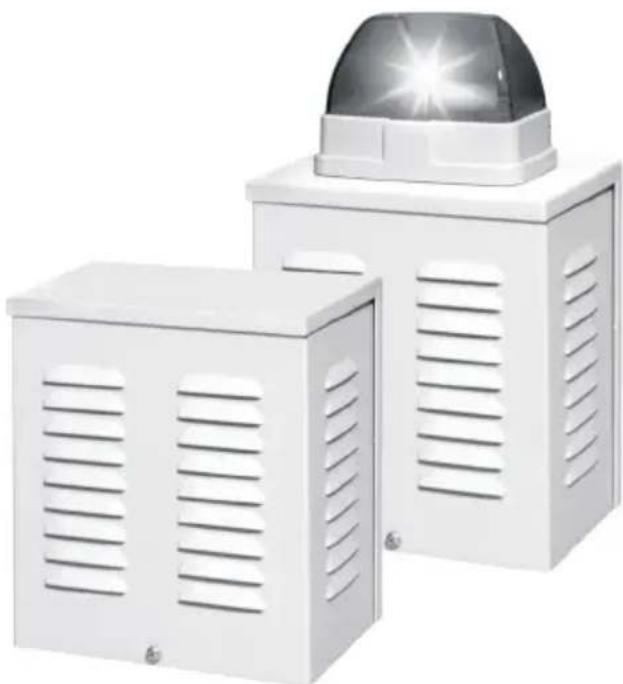
Flash and sounder Installation guide

Kombisignalgeber
Thank you for purchasing this acoustic or optical/acoustic flash and sounder equipment. You made the right decision in choosing this state-of-the-art technology, which complies with the current standards of domestic and European regulations. The CE has been proven and all related certifications are available from the manufacturer upon request. To maintain this status and to guarantee safe operation, it is your obligation to observe these operating instructions.
Notes
To prevent manipulation of the flash and sounder, install the product out of arm's reach (at least 3 meters high).
Additionally, please take local legislation into consideration. In some European countries, the use of sirens externally is forbidden, or the maximum alarm duration is restricted. In case of doubt, ask your local authorities for information.
Improper or careless installation work may lead to faults or malfunctioning. You should therefore read these instructions carefully. Observe the protection type specifications and follow the installation instructions for the lines and components used precisely.
Main features
- Acoustic or optical/acoustic flash and sounder, suitable for indoor and outdoor installation
- Strong, weatherproof aluminium casing
Interior protection grille - Extremely loud siren horn
- Xenon flash visible over large areas
Protection against tampering and removal
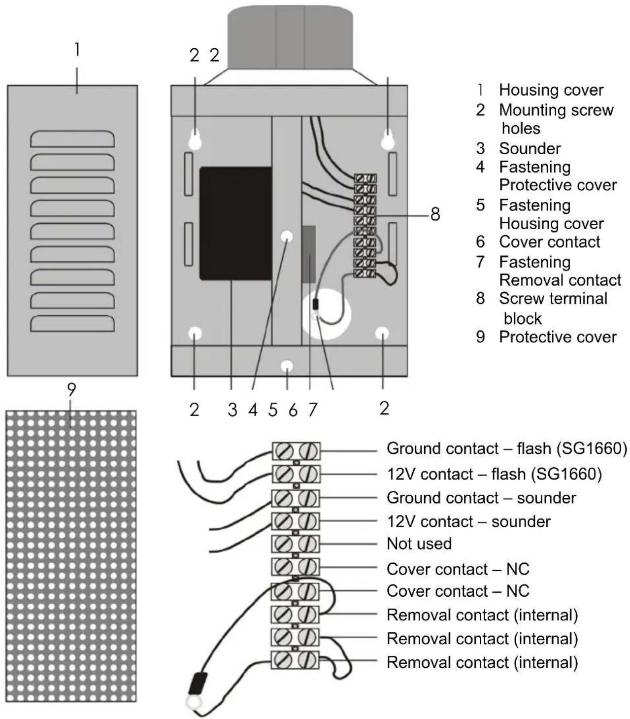
Installation
- Use the back of the flash and sounder case as a template for marking the drill holes (2). Drill the holes for the fixing screws.
- Pull the connector cable through the opening provided.
- Fix the rear of the casing and the removal contact (7) to the wall.
- Connect the cables to the terminal block (8) as described.
- Replace the protective cover (9) and the casing cover (1) and tighten the fixing screws.

IMPORTANT: Make sure you connect the cables to the right polarity, otherwise the flashlight may be irreparably damaged.
Connections
Use only shielded and grounded cables.
Connect the flash and sounder cables to the corresponding control or switching outputs of your alarm system. Check the total power consumption. You can also incorporate the cover contact into the tamper line of your alarm system.
Technical data
| Voltage supply 10-15 V DC | |
| Max. power consumption (without flash) | 340mA |
| Max. power consumption (with flash) | 750mA |
| Acoustic alarm 110dB @ 1m | |
| Protection type IP34 | |
| Operating temperature -25 to +55°C | |
| Dimensions (WxHxD) 190 x 310 x 120 mm | |
| Weight with flash / without flash 1,850g / 1,700g |
The manufacturer reserves the right to make technical modifications without prior notice.
Chere cliente, cher client,
Installatie-instructions
Kombisignalgeber


Brand : ABUS
Model : SG1650
Category : Alarm system