
Solo 16370 - Hedge Trimmers AL-KO - Free user manual and instructions
Find the device manual for free Solo 16370 AL-KO in PDF.
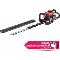



| Product type | Gasoline hedge trimmer |
| Brand | AL-KO |
| Model | Solo 16370 |
| Dimensions (L x W x H) | 1220 x 500 x 240 mm |
| Weight | 5.4 kg |
| Fuel | Mixture of unleaded gasoline (91 ROZ) and two-stroke oil (ratio 40:1) |
| Fuel tank capacity | 0.4 L |
| Engine displacement | 22.2 cm³ |
| Maximum engine power | 0.68 kW |
| Cutting length | 700 mm |
| Idle speed | 3100 ± 400 min⁻¹ |
| Sound pressure level LpA | 94.2 dB(A) (K = 3) |
| Sound power level LWA | 104.3 dB(A) (K = 3) |
| Vibration (front handle) | 2.12 m/s² |
| Vibration (rear handle) | 2.91 m/s² |
| Spark plug | CDK CMR6A / TORCH CMR6A / NGK CMR6A / NHSP LD AL6RC |
| Carburetor type | Walbro WYC35 |
| Main functions | Hedge and brush cutting, adjustable rear handle (0°-90°), manual start, emergency stop |
| Maintenance and cleaning | Daily air filter cleaning, spark plug check every 50 h, lubrication every 50 h, monthly fuel filter cleaning |
| Safety | Eye and ear protection required, 15 m safety zone, engine stop before maintenance, blade guard for transport |
| Spare parts and repairability | Original parts available from an authorized solo by AL-KO technical center; blades, spark plugs, filters, fuel lines replaceable |
| General information | Free user manual available in PDF; CE compliance (directives 2006/42/EG, 2000/14/EG, 2014/30/EU) |
Frequently Asked Questions - Solo 16370 AL-KO
User questions about Solo 16370 AL-KO
0 question about this device. Answer the ones you know or ask your own.
Ask a new question about this device
Download the instructions for your Hedge Trimmers in PDF format for free! Find your manual Solo 16370 - AL-KO and take your electronic device back in hand. On this page are published all the documents necessary for the use of your device. Solo 16370 by AL-KO.
USER MANUAL Solo 16370 AL-KO
| DE |
| EN |
| NL |
| FR |
| ES |
| IT |
| PL |
| HU |
| DA |
| SV |
| NO |
| FI |
| UK |




Table of contents
EN Translation of the original instructions for use.... 24
ALOIS KOBER GMBH Kötz, Germany
This documentation or excerpts therefrom may not be reproduced or disclosed to third parties without the express permission of the ALOIS KOBER GMBH.
(1)

(2)
(3)
(4)
OPERATION
(6)

(7)
→ Pause
→ Transport
→ Refueling
→ Maintenance
(8)
(9)
(13)
(11)
(12)

(19)

WARNING!
Cold start:
(16)
(6)
(10)
(21)

(22)
(23)

(26)
(27)
(28)
(28)
(29)
Designated use....24
Symbols on the machine....25
Product overview....26
Safety instructions....28
Operation....29
Maintenance and care.... 35
Troubleshooting....41
Storage....42
First aid....42
Thank you for choosing the solo by AL-KO hedge trimmer. We are delighted to be able to supply you with the solo by AL-KO hedge trimmer; these products are the result of a long development programme and many years of invention and experience.
The hedge trimmers 163-55 and 163-70 represent a combination of the benefits of the most modern technology and an ergonomic design; they have a low weight, are compact, and are used as professional machines for a wide range of applications.
Carefully read through this brochure, which provides detailed information on the various points that demonstrate the outstanding performance of these machines. Ensure that you fully understand the contents of this brochure, and comply with the advice and instructions it contains. In this way, you will be able to handle the machine safely and with confidence, and achieve the best possible results with your AL-KO hedge trimmer.

WARNING!
To avoid the risk of injuries, the user must carefully read these instructions for use before using the hedge trimmer. The manufacturer reserves the right to make changes to the technical data without advance notice.
Technical data may differ between one country and another. If you are passing the hedge trimmer on to another person, you must also hand over these instructions for use.
DESIGNATED USE
The hedge trimmer is intended exclusively for the trimming and cutting back of hedges and bushes; use for any other purpose is not permitted. Never use the hedge trimmer for anything other than the designated purpose.
SYMBOLS ON THE MACHINE
Symbols
Before reading these instructions, you must make yourself familiar with the meaning of the following symbols:
 | WARNING/DANGER Fuel/oil mixture |  | |
 | Read, understand, and comply with the instructions for use |  | Manual motor start |
 | Forbidden Emergency Stop |  | |
 | Smoking forbidden First aid |  | |
 | Use of naked flames forbidden Recycling |  | |
 | You must wear protective gloves ON / START | ### | |
 | Neither people nor animals may be in the working area. |  | OFF / STOP |
| ### | Wear eye and hearing protection CE marking |  |
PRODUCT OVERVIEW
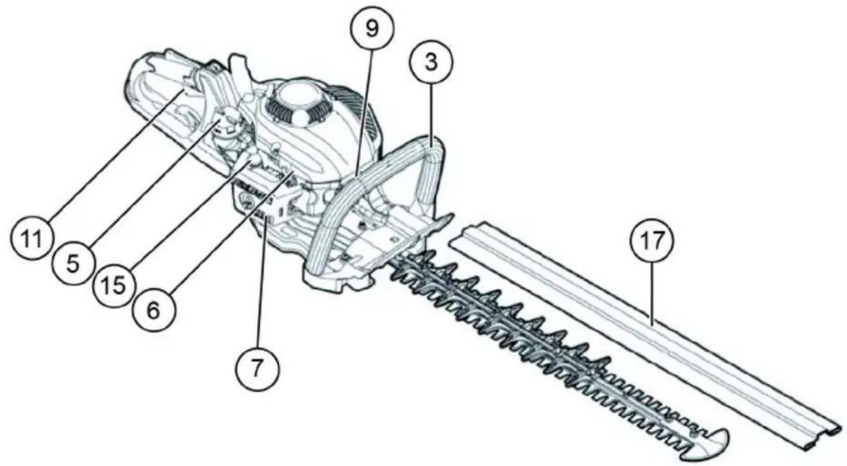

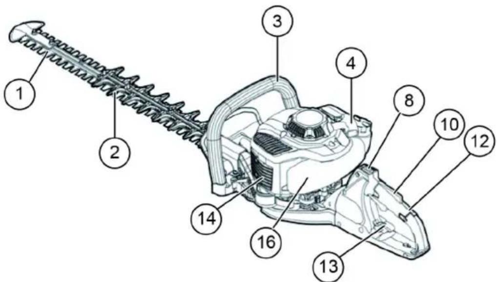
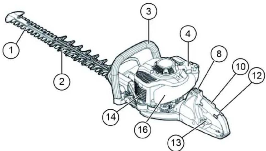
| NAMING OF COMPONENTS | NAMING OF COMPONENTS | NAMING OF COMPONENTS | |||
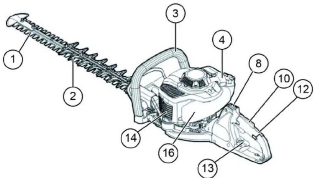
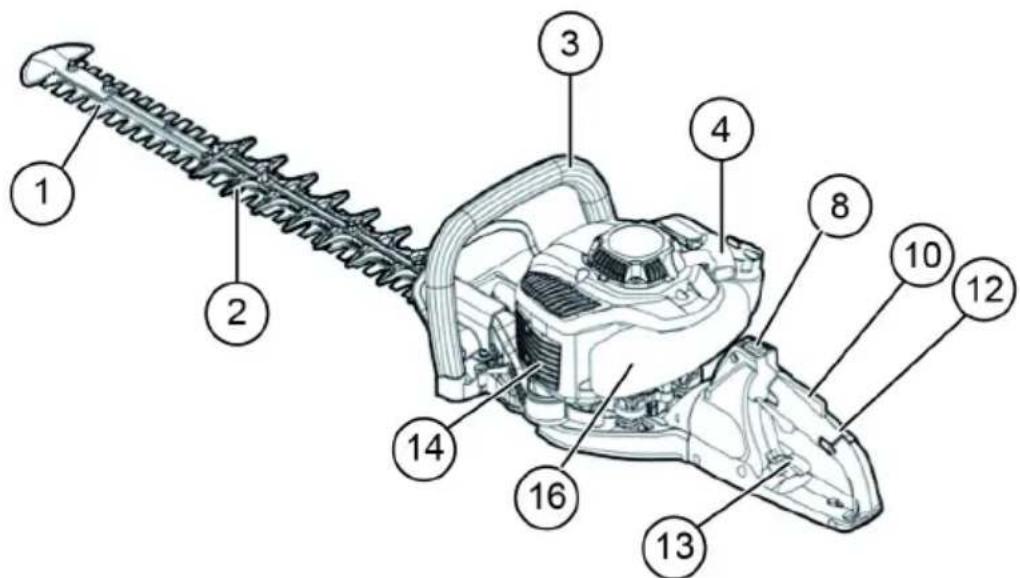
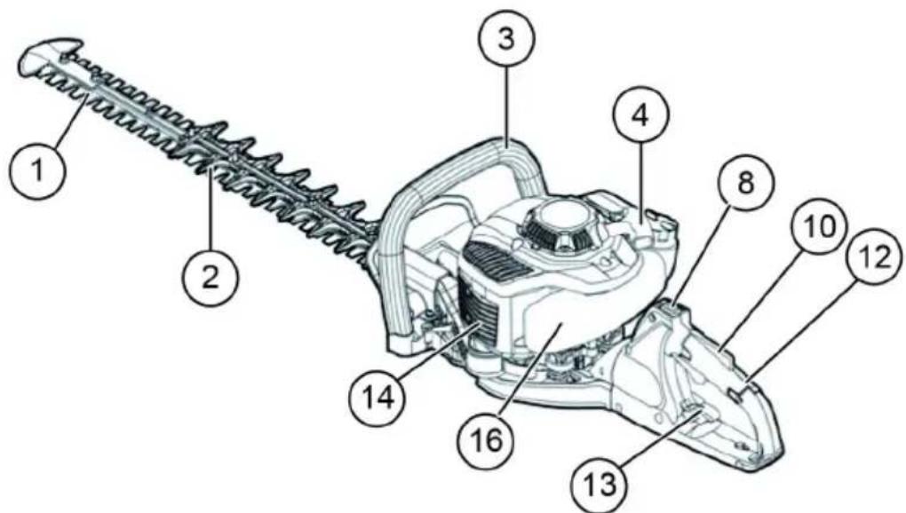
| 1 | Cutting knives 7 Carburettor | (not shown) | 13 Release lever for rear | handle | |
| 2 | Stationary blade 8 ON/OFF switch | 14 Silencer | |||
| 3 | Front handle 9 Spark plug | 15 Primer | |||
| 4 | Pull-cord starter 10 Release lever | 16 Fuel tank | |||
| 5 | Fuel tank cap | 11 Throttle lever | 17 Cover for cutting blade | ||
| 6 | Choke lever | 12 Rear handle | |||
TECHNICAL DATA
| Model | 163-55Item no.: 127325 | 163-70Item no.: 127326 | |
| Dimensions (L x W x H) [mm] 1140 x 500 x 240 | 1220 x 500 x 240 | ||
| Weight [kg] 5,2 5,4 | |||
| Volume (fuel tank) [l] 0,4 0,4 | |||
| Cubic capacity [cm3] 22,2 22,2 | |||
| Maximum motor power [kW] 0,68 0,68 | |||
| Cutting length [mm] 550 700 | |||
| Idling speed [min -1] 3100 ± 400 3100 ± 400 | |||
| Rotational speed for clutch engagement [min -1] 4500 4500 | |||
| Spark plug | CDK CMR6A;TORCH CMR6A;NGK CMR6A;NHSP LD AL6RC | CDK CMR6A;TORCH CMR6A;NGK CMR6A;NHSP LD AL6RC | |
| Carburettor type | Walbro WYC35 | Walbro WYC35 | |
| Sound pressure level LpA [dB(A)]EN ISO 10517 | 95 K = 3 | 94,2 K = 3 | |
| Sound power LWA [dB(A)]EN ISO 10517 | 107 K = 3 | 104,3 K = 3 | |
| Vibrations | front handle[m/s2] | 2,12 2,12 | |
| rear handle[m/s2] | 2,91 2,91 | ||
SAFETY INSTRUCTIONS
General safety rules
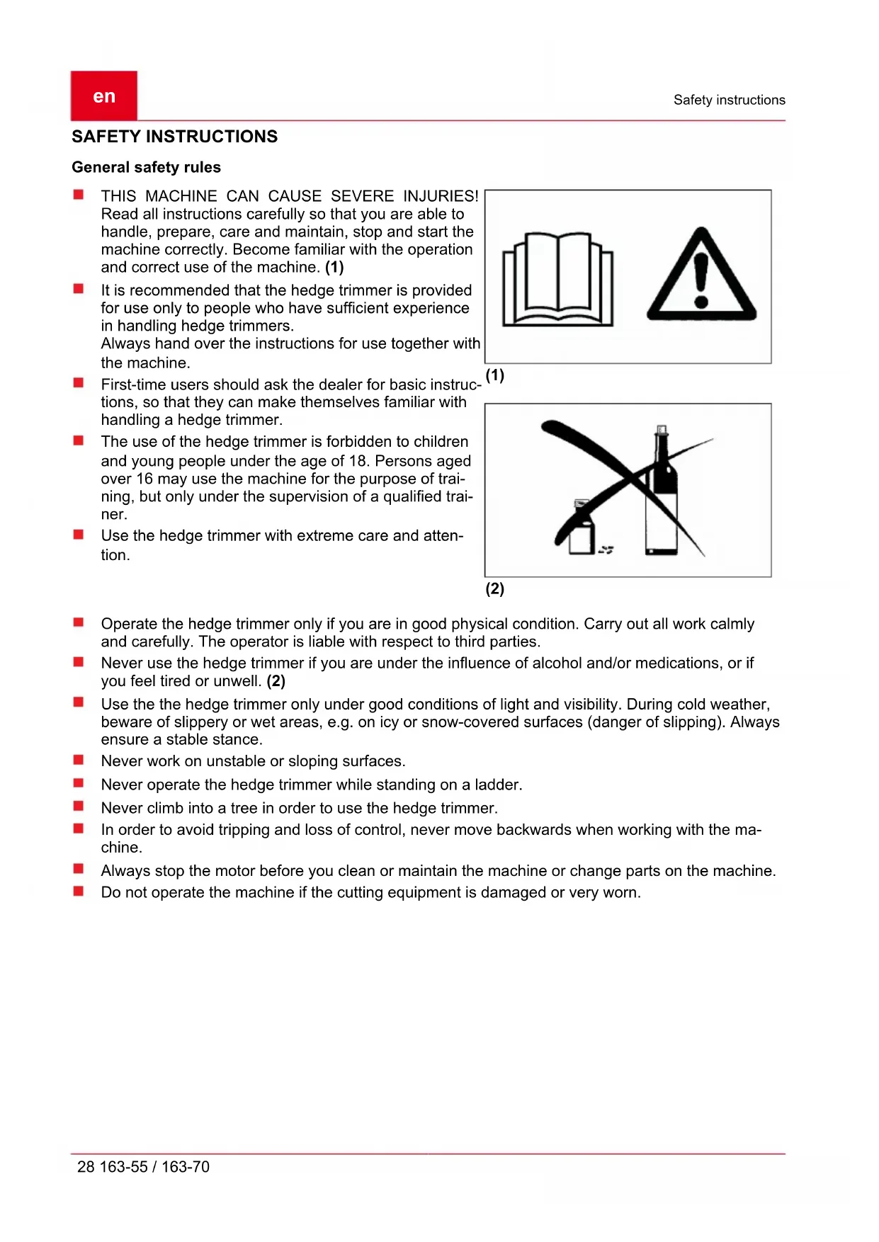
THIS MACHINE CAN CAUSE SEVERE INJURIES! Read all instructions carefully so that you are able to handle, prepare, care for, maintain, stop, and start the machine correctly. Become familiar with the operation and correct use of the machine. (1) It is recommended that the hedge trimmer be provided for use only to people who have sufficient experience in handling hedge trimmers. Always hand over the instructions for use together with the machine. First-time users should ask the dealer for basic instructions, so that they can make themselves familiar with handling a hedge trimmer. The use of the hedge trimmer is forbidden to children and young people under the age of 18. Persons aged over 16 may use the machine for the purpose of training, but only under the supervision of a qualified trainer. ■ Use the hedge trimmer with extreme care and attention.

(1)
(2)
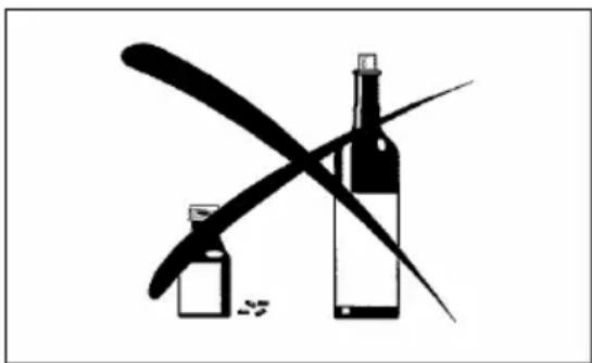
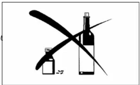
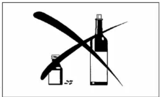
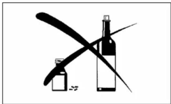
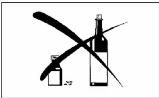
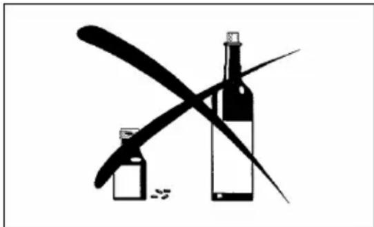
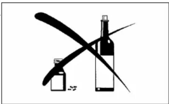
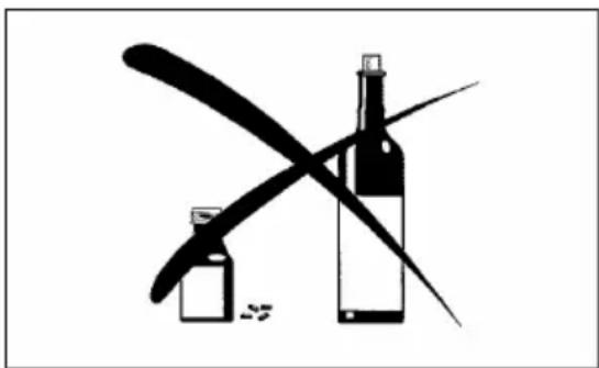
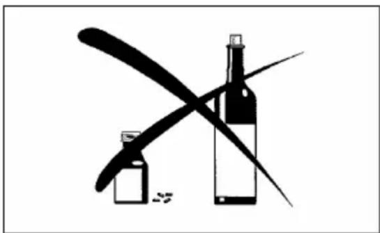
- Operate the hedge trimmer only if you are in good physical condition. Carry out all work calmly and carefully. The operator is liable with respect to third parties. Never use the hedge trimmer if you are under the influence of alcohol and/or medications, or if you feel tired or unwell. (2) Use the hedge trimmer only under good conditions of light and visibility. During cold weather, beware of slippery or wet areas, e.g. on icy or snow-covered surfaces (danger of slipping). Always ensure a stable stance. Never work on unstable or sloping surfaces.
- Never operate the hedge trimmer while standing on a ladder.
- Never climb into a tree in order to use the hedge trimmer. In order to avoid tripping and loss of control, never move backwards when working with the machine. Always stop the motor before you clean or maintain the machine or change parts on the machine. Do not operate the machine if the cutting equipment is damaged or very worn.
Personal protective equipment
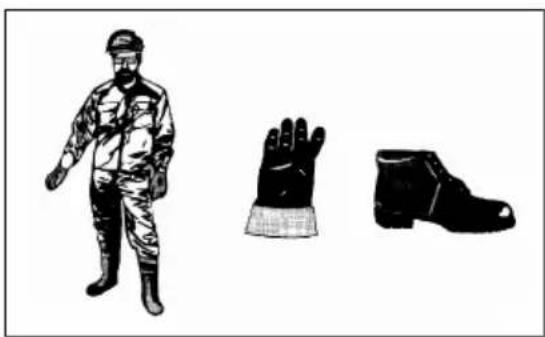
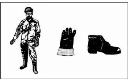
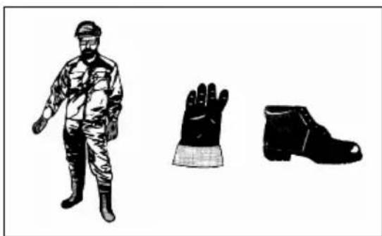
Wear appropriate and effective work clothing, i.e. the clothing should fit close to the body without causing obstruction. It is not permitted to wear jewellery or excessively loose clothing which could e.g. get caught in the machine, vegetation, or undergrowth.
In order to prevent injuries to the eyes, hands, and feet, and also to the operator's hearing, the protective equipment/clothing listed below must be worn when working with the hedge trimmer.
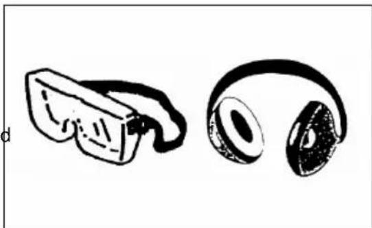
While working with the hedge trimmer, wear protective spectacles or a visor in order to prevent injuries to the eyes. (3)
Wear effective hearing protection in order to prevent damage to the hearing (hearing protector muffs, earplugs, etc.). (3)
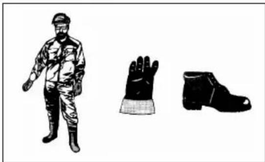
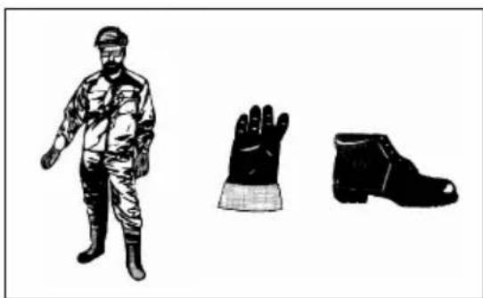
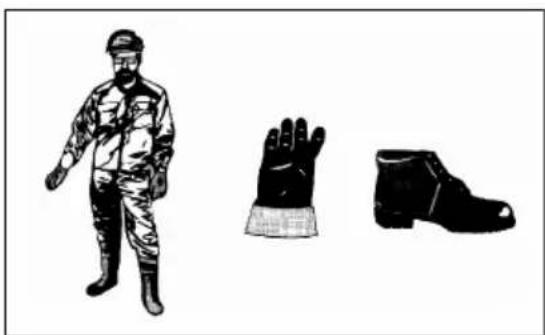
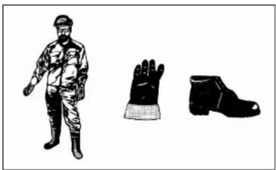
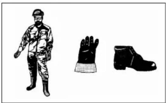
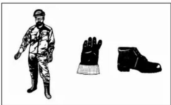
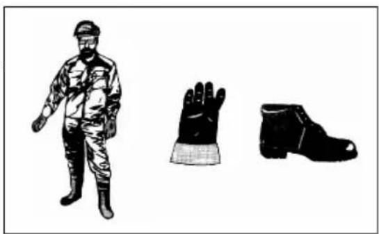
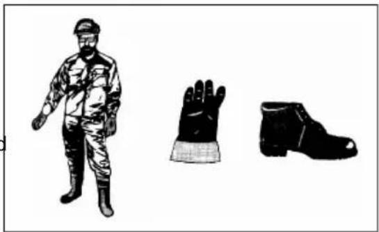
We strongly recommend that the operator wears work overalls. (4)
Special gloves made of thick leather are a component of the prescribed equipment, and they must be worn when working with the hedge trimmer. (4)
When working with the hedge trimmer, always wear robust shoes with non-slip soles. Such shoes protect from injuries, and provide a secure grip. (4)
(3)
(4)
OPERATION
Safety instructions relating to operation
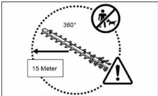
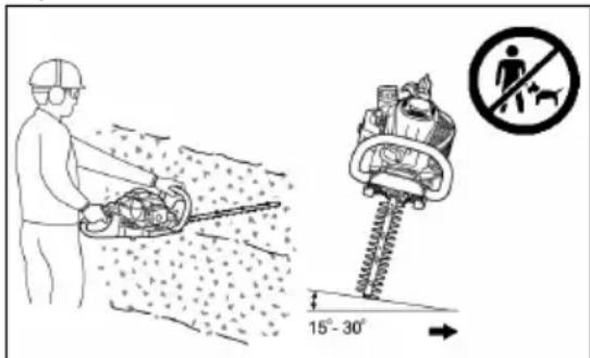
Ensure that no children or other persons are present within a working range of 15 m; in addition, beware of animals in the working range.
Confirm the operational safety of the hedge trimmer before each use.
Confirm that the throttle lever works correctly. Ensure that the throttle lever can be moved smoothly and easily. Confirm that the throttle lever locking mechanism works correctly. Ensure that the handles are clean and dry, and confirm that the ON/OFF switch works correctly. Keep the handles free from oil and fuel.
Start the hedge trimmer only as specified in the instructions for use.

WARNING!
Do not start the motor in any other way!
Use the hedge trimmer for its designated purpose only. Start the motor of the hedge trimmer only when the hedge trimmer is fully assembled. Operation of the hedge trimmer is permitted only when all equipment specified for its operation has been fitted to it.
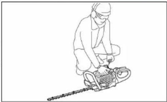
Before starting the hedge trimmer, ensure that the blade is not touching any object (e.g., branches, stones, etc.). Stop the motor immediately if there are any problems with it. While operating the hedge trimmer, firmly hold both the front and rear handles by placing your fingers around the handles. Ensure that the handles are clean and free of moisture, oil, and lubricants. Always ensure a stable, balanced stance. This machine must be used only in the open air. Pay continuous attention to the working environment, and stay prepared for possible dangerous situations of which you may not be aware because of the noise created by the motor. Always operate the hedge trimmer in such a way that you do not inhale the exhaust fumes. Never run the motor in enclosed spaces (danger of asphyxiation and gas poisoning). Carbon monoxide is an odourless gas. Ensure that there is sufficient ventilation at all times. Stop the motor when you take a break or when you are leaving the hedge trimmer unsupervised. Place the hedge trimmer in a secure location in a safe place where it cannot endanger people, and where ignition of flammable materials and damage to the machine cannot occur. Never place the hot hedge trimmer on dry grass or other flammable materials. Always keep the motor and silencer free of trimmings, leaves, and excess lubricant, in order to avoid the danger of a fire. Never operate the motor if the exhaust silencer is damaged.
Stop the motor before transporting the machine.
Stop the motor before the following activities:
- Removing a blockage,
- carrying out inspections, maintenance work, or other work on the machine.
When transporting in a vehicle, lay the hedge trimmer down in a safe position, so that leakage of fuel is avoided.
Before transporting the hedge trimmer, ensure that the fuel tank is completely empty, so that leakage of fuel is avoided.
Before transporting or storage, always place the cover on the cutting blade.
Before you start cutting with the hedge trimmer, inspect the working area for wires, string, glass, and other foreign bodies which could come into contact with the cutting blade.
Electric shock: You must beware of all types of electric wiring and electric fences. Examine the complete working area for electric wires and cables before using the hedge trimmer.
When starting the motor, and during operation, you must avoid any contact with the cutting blade.
During operation, all protective devices provided with the machine, such as covers, must be correctly attached to the machine.
→ Break
→ Transport
→ Filling
→ Maintenance
■ Remove sand, stones, nails, wires, etc. from the working area. Foreign bodies may damage the cutting blade.
Before cutting the hedge, cut off branches of 8 mm or thicker, using branch shears.
Before starting to cut, make sure that the cutting knives have reached their full working speed.
After releasing the throttle lever, there is a short period before the cutting knives come to a stop.
Do not operate the hedge trimmer at a high idling speed. If the idling speed is set too high, it is no longer possible to adjust the speed of the cutting knives by means of the throttle lever.
During the cutting process, hold the hedge trimmer in such a way that the blade creates an angle between 15° and 30° with the cutting line.
Take particular care when cutting hedges close to wire fences.
Ensure that the cutting blade does not touch any hard objects such as wire fences, stones, or the ground. If such objects are touched, cutting knives may burst, jerk, or break off.
If the cutting blade makes contact with stones or other hard objects, switch off the motor immediately and examine the blade for damage. Replace a damaged cutting knife before continuing the work.
Take regular breaks. AL-KO recommends taking a break of 10 to 20 minutes after 50 minutes of cutting work.
Always try to operate the hedge trimmer with the minimum emission of sound and pollutants. In particular, confirm that the carburettor is set correctly, and comply with the prescribed mixing proportions of fuel and oil.
Never attempt to remove jammed material while the cutting knives are in motion. Switch the machine off, put it down, and only then remove the jammed material.
Filling
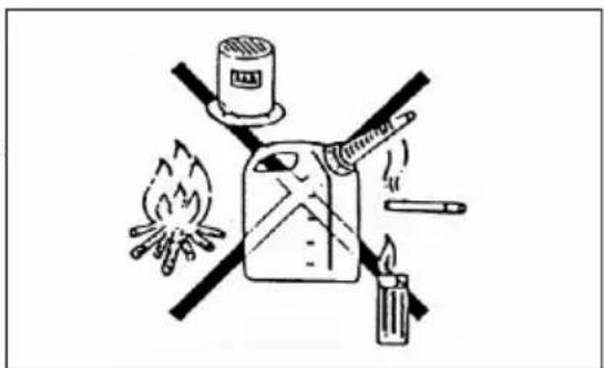
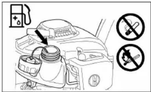
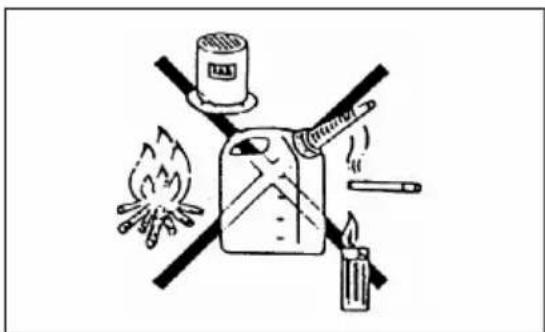
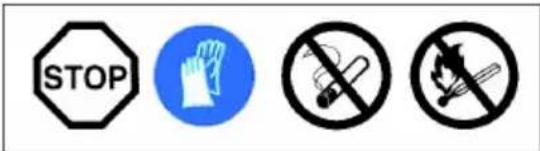
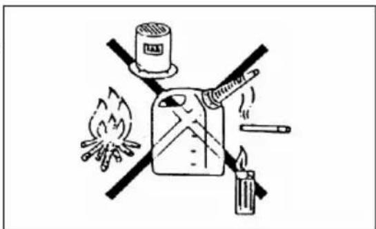
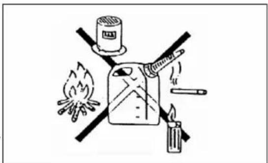
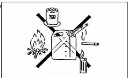
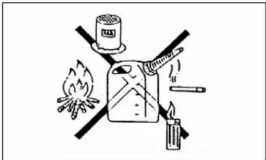
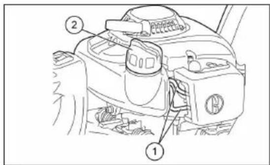
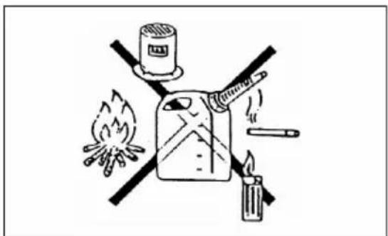
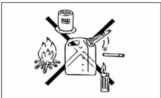
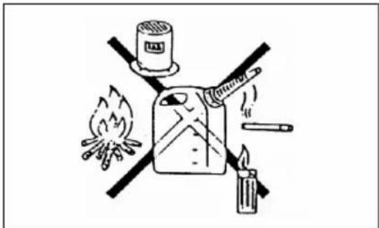
Stop the motor (7) before filling the tank, maintain an appropriate distance from open flames, (8) and do not smoke.
Never fill the machine while the motor is running or hot.
Avoid skin contact with mineral oil products. Do not inhale fuel vapours. When filling, always wear protective gloves. Change and clean protective clothing regularly.
In order to avoid ground contamination (environmental protection), ensure that no fuel or oil enters the soil. Wipe spilt fuel off the hedge trimmer immediately. Allow textiles used to wipe off fuel to dry in a well ventilated place before disposing of them. Otherwise, sudden self-ignition may occur.
■ Ensure that your clothing does not come into contact with fuel. If fuel has got onto your clothing, change it immediately (danger!).
- Check regularly that the cap of the fuel tank is positioned correctly.
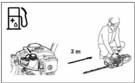
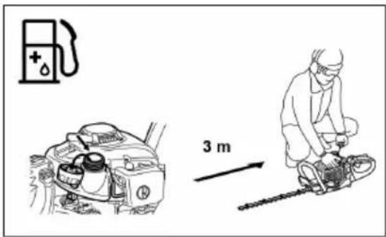
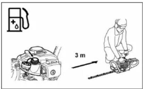
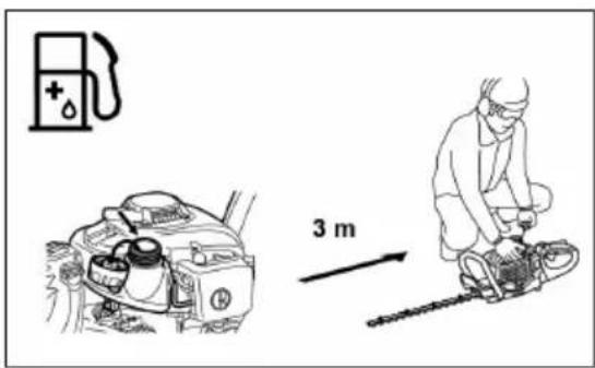
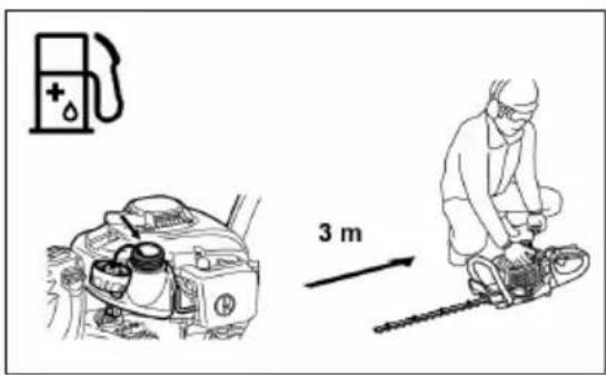
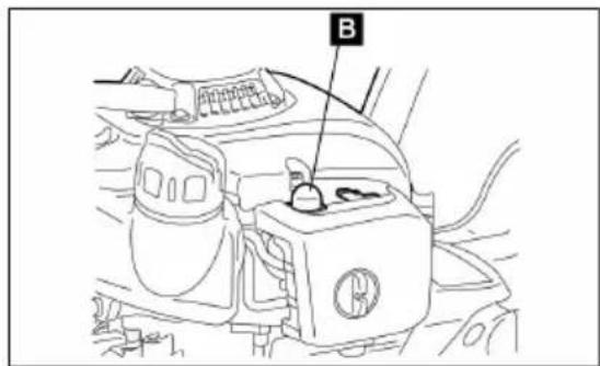
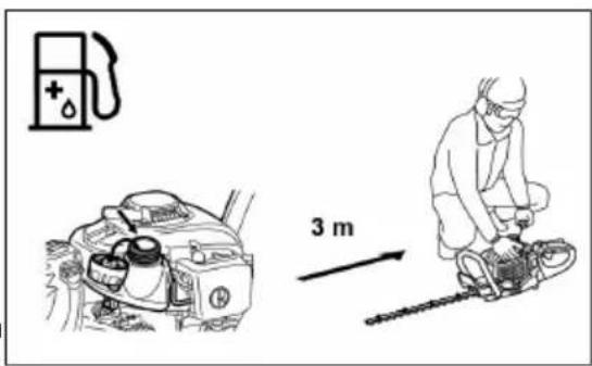
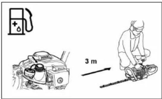
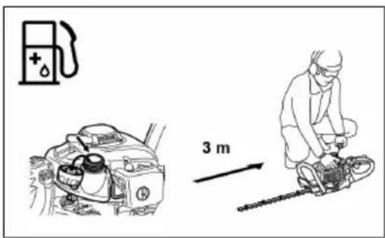
Screw on the tank cap to the correct tightness. Move at least 3 m away from the filling location before starting the motor. (9)
Never fill the machine in enclosed spaces. Fuel vapours may gather at ground level, and thereby result in a deflagration or even an explosion.
■ Transport and store fuel exclusively in containers approved for that purpose. Ensure that children have no access to stored fuel.
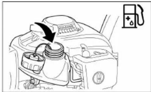
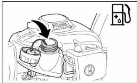
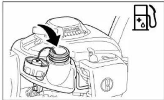
- Carefully clean the area around the tank cap so that no dirt enters the fuel tank.
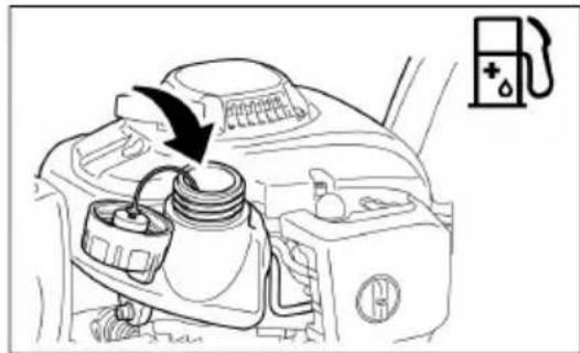
Unscrew the cap and fill the tank with fuel. To filter the fuel, use a funnel with an appropriate filter insert.
Screw on the tank cap again by hand.
■ After fuelling, clean the area around the cap and the tank.
You must wipe off spilt fuel (danger of fire).

(7)
(8)
(9)
(13)
Fuel/oil mixture
The hedge trimmer is powered by a two-stroke motor with a high level of performance.
This motor is operated using a mixture of fuel and two-stroke oil. The motor is designed for lead-free regular petrol with an octane rating of ROZ 91. If this fuel is not available, you can use a fuel with a higher octane rating. This does not damage the motor, but the operating behaviour may be poorer.
Similar problems arise if leaded fuel is used. In order to achieve optimum operation of the motor, and to protect your health and the environment, only lead-free fuel should be used.
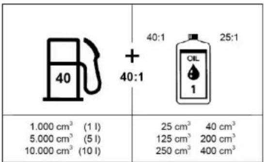
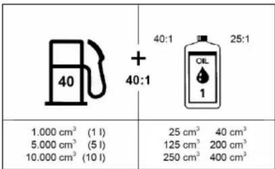
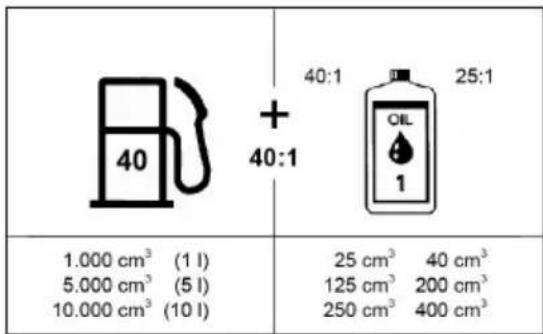
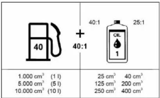
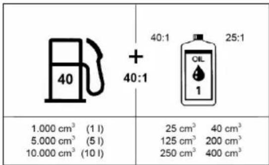
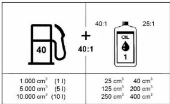
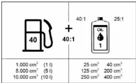
The motor is lubricated by the two-stroke oil which is mixed with the fuel. The motor is designed for operation with solo by AL-KO two-stroke oil in a mix ratio of 40:1 (environmental protection). The low mix ratio guarantees minimum pollutant emission simultaneously with long working life and reliable operation. The mix ratio of 40:1 (solo by AL-KO two-stroke oil) must be complied with, otherwise reliable operation of the hedge trimmer cannot be guaranteed.
The correct mix ratio:
Carburettor fuel:
■ Prescribed two-stroke oil = 40:1 or ■ two-stroke oil from another manufacturer = 25:1 recommended

(11)

(12)

To prepare the mixture, in an approved container which fulfils or exceeds all locally applicable requirements, first mix the whole amount of oil with half the required amount of fuel. Then add the rest of the fuel. Mix the mixture thoroughly before adding it to the tank of the hedge trimmer. In order to ensure reliable operation, do not add more motor oil than specified. Otherwise, the result is just the creation of more combustion residue which pollutes the environment and blocks the exhaust duct and the silencer. In addition, the fuel consumption rises and the performance decreases.
Handling mineral oil products
Extreme care is required when handling fuels. Fuels may contain substances which are similar to solvents. Refuel the machine exclusively in a well ventilated location in the open air. Do not inhale the fuel vapours, and avoid any skin contact with fuels and oils.
If the skin comes into repeated contact with such substances over an extended period of time, it dries out.
This can result in a very wide number of skin disorders. There have also been reports of allergic reactions.
Eye irritations can occur if oils, fuels, etc. get into the eyes.
If this occurs, flush the eyes immediately with clean water. If the eye irritation continues, contact a doctor immediately.
Adjusting the angle of the rear handle
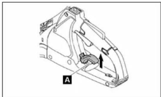
The rear handle can be turned up to 90 degrees to the right or left, and locked.
How to adjust the angle:
1. Pull the release lever (19A) to release the handle lock. 2. Turn the handle to the desired angle between 0 and 90 degrees. 3. Ensure that the release lever (19A) returns to its original position, and that the handle lock has engaged.
(19)

CAUTION!
Do not actuate the throttle lever while the handle lock is released. Do not release the handle lock during cutting work.
Starting the machine
Move at least 3 m away from where refuelling took place. Place the hedge trimmer on a clean base. Ensure that the cutting blade does not come into contact with the ground or other objects.

Cold start:
If the motor is cold, or has been switched off for more than 5 minutes, and after refuelling.
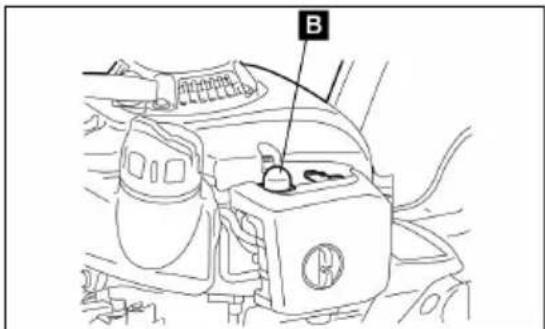
2. Gently press the starter pump several (7 to 10) times (15B), until fuel enters the starter pump.
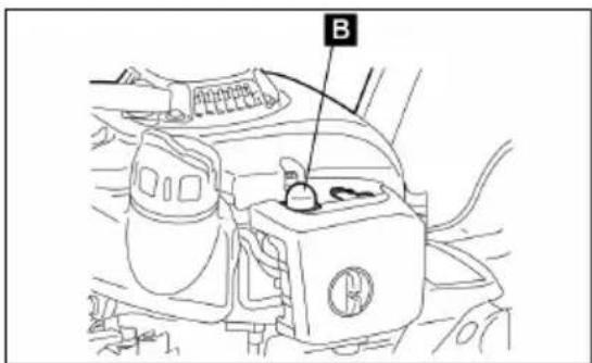
(15)
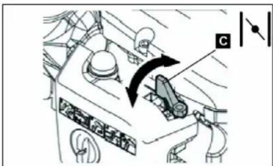
3. Bring the choke lever (16C) into position
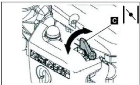
(16)
4 Hold the machine firmly, pointing downwards, so that you do not lose control when starting the motor using the pull-cord. Failure to comply with this can result in a sudden jerk or in contact with the cutting blade, and thus to severe injury, material damage, and/or damage to the machine. 5 Pull the starter handle slowly by 10 to 15 cm until you feel resistance. 6 Pull strongly on the starter handle. In doing so, you feel resistance, and the motor starts. 7 Let the motor run for about one minute at an appropriate speed before applying full power.
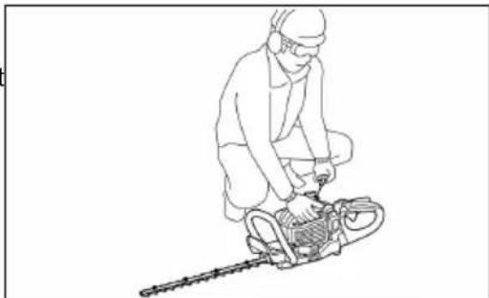
(6)
Stopping the machine
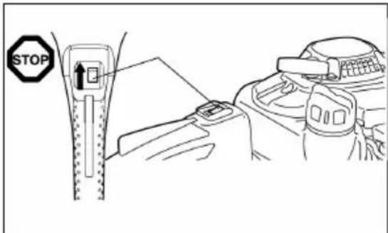
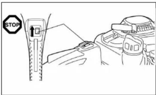
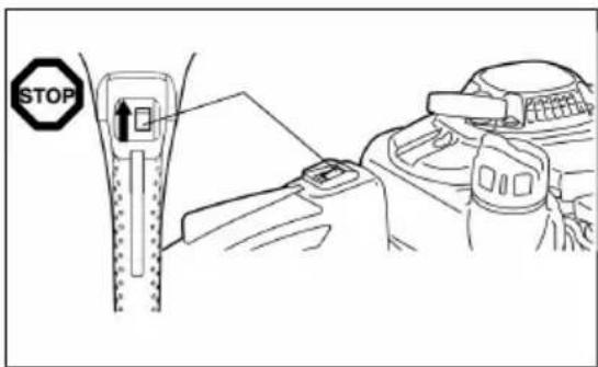
1 Completely release the throttle lever. 2 Set the ON/OFF button to "O" (off). The motor runs down and stops.

(7)
MAINTENANCE AND CARE
Maintenance instructions
Be considerate of the environment and of your neighbours. Always try to operate the hedge trimmer at the lowest possible noise and pollutant emissions. Above all, confirm that the carburettor is set correctly. - Clean the hedge trimmer regularly, and check that all bolts and nuts are firmly tightened. ■ Never maintain or store the hedge trimmer in proximity to open flames or sparks (fire hazard).

(10)
Switch off the motor and disconnect the spark plug lead before cleaning/replacing/sharpening the cutting blade or carrying out other maintenance work. - Store the hedge trimmer in a well ventilated location. The storage must be high enough or lockable, in order that children cannot access the hedge trimmer. ■ Undertake only those repairs on the hedge trimmer for which you are sufficiently qualified. ■ Never straighten or weld damaged cutting machines. With the motor switched off, check the cutting blade regularly for damage. ■ Ensure that cutting tools are always correctly sharpened. The knives are sharp; therefore always wear safety gloves when handling and sharpening the knives.

CAUTION!
Comply with all accident prevention measures laid down by the relevant trade associations and authorities and recommended by insurers.
Do not undertake any changes whatsoever to the hedge trimmer, because this would put your safety at risk.
The operator may carry out only the maintenance and repair tasks described in these instructions for use. All other maintenance work must be carried out by authorised maintenance personnel.
Use only original replacement parts and original accessory parts which you have obtained from authorised solo by AL-KO service centres.
The use of unapproved accessory parts and tools creates an increased risk of accidents and injuries. For personal injury and/or material damage caused by the use of unapproved replacement and/or accessory parts, solo by AL-KO accepts no liability.
Sharpening the knives
If the knives have become blunted, and no longer cut well, sharpen the positions on the blades which are cross-hatched in the diagram (20-3). Do not sharpen the contact (slide) surfaces of the upper and lower knives. (20-1) Flat grinders
(20-2) Cutting cross-section
Switch off the motor, disconnect the spark plug lead, and ensure that the cutting blade and the knife are secured before you grind the knives. ■ Wear gloves, safety spectacles, etc. Do not grind off too much material. That would remove the hardened layer, and the knives would become blunt very quickly when used.

(20)
Resetting the separation between upper and lower knives
Grind the upper/lower knives. If you do not obtain a clean cut, even though the knives are sharp enough, set the distance between the knives as follows:
1 Loosen the bolts in order to remove the cutting blade from the machine. 2 Loosen the nut (21-1) by means of a ring or open-jawed spanner. 3 Slightly tighten the holding bolt (21-2) by means of a Torx spanner, until you feel resistance, and then loosen the holding bolt again by a quarter-turn.
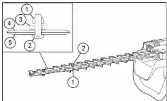
(21)
4 Hold the holding bolt (21-2) in place, and tighten the nut (21-1) securely. 5 Apply a little oil to the contact surfaces of the knives. 6 Start the motor and run it for one minute, during which time you repeatedly accelerate and decelerate. 7 Measure the time which the knives require to come to a stop after releasing the throttle lever. If this takes two seconds or longer, stop the motor and repeat steps 2 to 7. 8 Stop the motor and touch the surface of the knives. If the knives are not too hot to be touched, then the setting is correct. If the knives are too hot to be touched, loosen the holding bolt slightly (2), and repeat steps 6 to 8. 9 Re-attach the cutting blade to the machine, using the bolts.

Stop the motor and ensure that the cutting knives have come to a complete stop before you adjust settings.
There are slots in the knives close to bolt (21-2). If these slots are blocked with dust, clean them.
Checking and adjusting the idling speed
When the motor is idling, the cutting knives should be at a standstill.
The idling speed should be set to 3,100 min-1 (rpm). Use the idling speed screw to set the idling speed (when the motor is idling, the cutting knives must be at a standstill).
- If the knives move during idling, turn the idling speed screw anticlockwise in order to reduce the idling speed.
- If the motor stops while idling, turn the idling speed screw clockwise in order to increase the idling speed.
If the cutting knives continue to run even after setting the idling speed, contact your authorised service centre.
- The clutch should engage at 4,000 min-1 (rpm) at the earliest.
- Check the ON/OFF switch, the handle grip release lever, and the throttle lever for correct functioning.
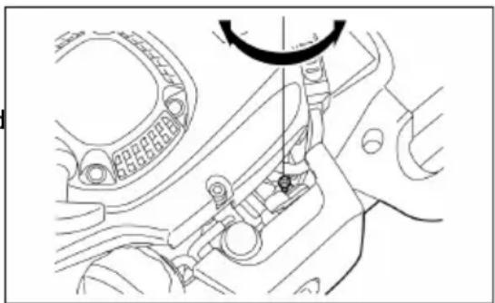
(22)
Cleaning the air filter

DANGER!
Open flames are strictly forbidden.
Check and clean the air filter every day, or after 15 operating hours at the most.
Turn the choke lever so that it is completely closed, and keep the carburettor free of dust and dirt.
■ Loosen the holding bolt (23-1).
■ Remove the air filter by pulling the air filter cover (on the filter's rear side) forwards.
If the insert (foam) (23-2) is contaminated with oil, forcefully press out the insert.
In the case of heavy contamination:
- Remove the insert (foam) (23-2), immerse it in hot water or in water with a diluted neutral cleaning agent, and then allow the insert to dry fully.
- Clean the insert (felt) (23-3) with petrol, and allow the insert to dry fully.
Let the inserts dry fully before you re-install the air filter. If the inserts are not dried sufficiently, difficulties in starting the motor may arise.
Use a cleaning rag to wipe off oil adhering around the air filter.
Fit the air filter cover immediately after cleaning, and secure the cover by means of the holding screw (23-1).

Important points when handling the air filter inserts
- Clean the inserts several times per day if excessive dust adheres.
If operation is continued when the inserts are contaminated with oil, oil can leak from the air filter and result in oil contamination.
Checking the spark plug
Check and clean the spark plug after 50 operating hours at the most.
Use only the supplied Universal bolt spanner to screw the spark plug in and out.
The separation between the two electrodes of the spark plug should be between 0.7 and 0.8 mm. Correct the separation if it is too large or too small. If the spark plug is affected or contaminated by carbon, clean it thoroughly or insert a new spark plug. Use only replacement spark plugs of the same type.
Lubrication
Every 50 operating hours, press lubricant grease into the grease nipple (26-1).

You must comply with the prescribed lubrication intervals and lubricant quantities.
- Otherwise, the machine may be damaged through insufficient lubrication.

(23)

(26)
Cleaning the fuel filter
(Suction head on the fuel tank)

WARNING!
Open flames are strictly forbidden.
Check and clean the fuel filter monthly, or after 50 operating hours at the most.
The fuel required by the carburettor is filtered by the fine filter (27-1) in the suction head. - Carry out regular visual inspections of the fine filter.
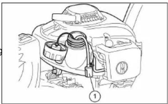
(27)
In order to inspect the fine filter (27-1), open the tank cap, and use a wire hook to pull the suction head out through the tank opening. If the fine filter (27-1) is hardened, contaminated, or blocked, then replace it (27-1) with a new filter. - Replace the fine filter (27-1) at least every 3 months, so that sufficient supply of fuel to the carburettor is ensured. An insufficient fuel supply results in difficulties when starting the motor, and to a reduction in the maximum rotational speed.
Replacement of the fuel pipe

WARNING!
Open flames are strictly forbidden.
Inspect and clean the fuel pipe (28-1) every day, or after 10 operating hours at the most.
- Replace the fuel pipe (28-1) after 200 operating hours or at least every year, regardless of the number of operating hours. Otherwise, a fire may occur because of leaking fuel. If you notice leaking fuel, replace the fuel pipe (28-1) immediately.
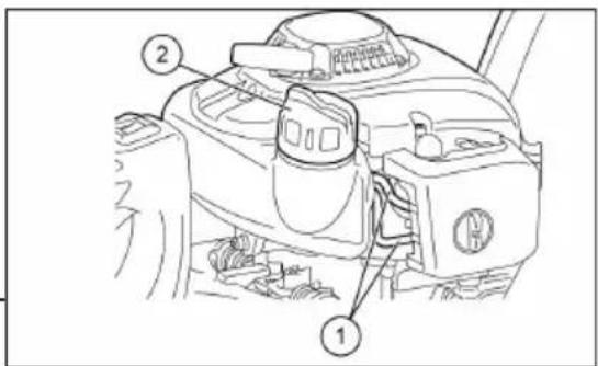
(28)
Replacing the tank cap
If the tank cap (28-2) is cracked or otherwise damaged, replace it. Over time, the tank cap shows signs of wear. Replace it every two to three years.
If maintenance work and settings need to be carried out which are not explained in these instructions for use, contact your authorised solo by AL-KO service centre.
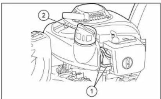
(28)
Daily inspections and maintenance tasks
Carry out the following maintenance tasks regularly, so that your machine has a long working life, and to avoid damage to the machine.
Before use:
Check the machine for loose bolts and missing parts. Ensure in particular that the bolts of the cutting knives are tightened correctly. - Confirm that the cooling air passages and cylinder fins are not blocked. Clean these when required. - Clean the fuel tank, and check for leaks and for foreign bodies in the tank.
After use:
- Clean the hedge trimmer externally, and check it for damage.
- Clean the air filter. If you are working under very dusty conditions, clean the filter several times each day.
- Check the cutting knives for damage, and ensure that they are correctly mounted.
Maintenance schedule
| - Throttle lever Confirm correct functioningAfter every refuelling | ||
| - ON/OFF switch Confirm correct functioning | ||
| Before every use | - Motor Visual inspection for damage and firm fit | |
| - Bolts and nuts Confirm general state and tight fit | ||
| - Air filter Clean | ||
| - Cooling air duct Clean | ||
| - Cutting equipment Check for damage and sharpness | ||
| - Idling speed Inspect (cutting equipment must not move) | ||
| - Fuel tank Inspect and clean | ||
| very 50 hours | - Transmission housing Lubrication | |
| - Spark plug | Inspect, and replace if necessary | |
| Every year | - Fuel pipe Replace | |
| Every two years | - Tank cap | Replace |
| Before long-term storage | - Fuel tank Empty and clean | |
| - Carburettor | Run the motor until the fuel has been fully consumed. | |
| - Suction head Replace | ||
TROUBLESHOOTING
| Problem System | Observed Cause | ||
| Motor does not start, or only with difficulty | Ignition system | Ignition spark present Defect in | fuel supply or compression system, mechanical defect |
| No ignition spark ON/OFF switch | actuated, defect or short circuit in wiring, spark plug or spark plug cap defective, ignition module defective | ||
| Fuel supply Fuel tank is not | empty Choke not in correct position, carburettor defective, suction head (fuel filter) contaminated, fuel pipe twisted or interrupted | ||
| Compression | Inside the motor Cylinder base | gasket defective, crankshaft seals damaged, cylinder or piston rings defective | |
| On the outside of the motor Spark plug seal defective | |||
| Mechanical defect | Starter does not engage Broken | starter spring, broken parts within the motor | |
| Hot start problems | Tank not empty, spark plug present | Carburettor contaminated | |
| Motor starts, but stops immediately | Fuel supply Tank not empty | Idling speed set incorrectly; suction head or carburettor contaminated | |
| Problem with ventilation opening in fuel tank, fuel supply pipe interrupted, cable or ON/OFF switch defective | |||
| Insufficient power | Several systems may be affected simultaneously | Motor is idling Air filter contaminated, carbu-rettor contaminated, silencer blocked, outlet duct in cylinder blocked | |
STORAGE
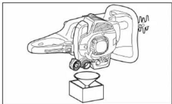
If you wish to store the machine for an extended period, completely drain the fuel from the tank and carburettor as described below: Empty the fuel tank completely. Unscrew the spark plug, and place a few drops of oil in through the spark plug opening. Then slowly pull the starter pull-cord, so that the whole inside of the cylinder film is covered with an oil film, and screw the spark plug back in.
(29)
Remove dust and dirt from the cutting knives and from the outside of the machine, wipe the knives and machine with an oily rag, and keep the machine in a very dry location.
FIRST AID
In case of an accident, ensure that there is a correctly filled First Aid box as per DIN 13164 close to the working location.
Immediately replace all materials removed from the First Aid box.
If you require emergency aid, provide the following information:
- Location of the accident
- What happened – Number of injured persons
- Severity of injuries - your name

EC DECLARATION OF CONFORMITY
We hereby declare that this product, in the version placed on the market by us, complies with the requirements of the harmonised EU Directives, EU safety standards and the product-specific standards.
Product Manufacturer Duly authorised person
| Petrol-driven hedge trimmer | AL-KO Geräte GmbH | Andreas Hedrich |
| Ichenhauser Str. 14 | Ichenhauser Str. 14 | |
| Serial number | 89359 Kötz | 89359 Kötz |
| G2442445 | DEUTSCHLAND | DEUTSCHLAND |
Type EU Directives Harmonised standards
| 163-55 | 2006/42/EG | EN ISO 10517 |
| 163-70 | 2000/14/EG | EN ISO 14982 |
| 2014/30/EU | EN ISO 22867 | |
| EN ISO 22868 |
Sound power level Conformity evaluation Kötz, 2016-08-26
| measured / guaranteed163-55104,3 dB(A) / 107 dB(A)163-70104,3 dB(A) / 107 dB(A) | 2000/14/EGAppendix V | Wolfgang HugotaManaging Director |
TRANSLATION OF THE ORIGINAL USER MANUAL
Table of contents
(1)
(2)
(3)
(4)
OPERATION
(6)
(8)
(9)
(13)
Fuel-oil mixture
(11)

(12)
(19)

CAUTION!
Cold start:
(16)
(6)
(10)
(21)
(22)
(23)
(26)
(27)
nl
(28)
(28)
(29)
EG DECLARATION OF CONFORMITY
(1)

(2)
(3)
(4)
USE
(6)
(8)
(9)
(13)
Fuel/oil mixture
(11)

(12)

(19)

WARNING!
Cold start:
(16)
(6)
Tool stop
(10)
(21)

(22)
(26)
(27)
(28)
(28)
(29)
CE DECLARATION OF CONFORMITY
(1)
(2)
(3)
(4)
OPERATION
(6)
(7)
(18)
(8)
(9)

(13)

(11)

(12)

(19)

ATTENTION!
(15)
(16)
(6)
(10)
(21)
(22)
(23)
(26)
(27)
(28)
(28)
(29)
(1)

(2)
(3)
(4)
USE
(6)
(18)
Refueling
(8)
(9)
(13)
Fuel-oil mixture
(11)
(12)

(19)

WARNING!
(16)
(6)
(10)
(21)

(22)
(23)
(26)
(27)
(28)
(28)
TROUBLESHOOTING SHEET
(29)
(1)
(2)
(3)
(4)
OPERATION
(6)
(7)
(8)
(9)
(13)

(11)
(12)

(19)

NOTE!
Cold start:
(16)
(6)
(10)

NOTE!
(20)
(21)
(22)
(23)

(26)
(27)
pl
(28)
(28)
(29)
EU DECLARATION OF CONFORMITY
(1)
(2)
(3)
(4)
USE
(6)
(18)
(8)
(9)

(13)
(11)
(12)

(19)

WARNING!
Cold start:
(16)
hu
(6)
(10)
(21)
(22)
(23)
(26)
(27)
(28)
Tank top replacement
(28)
(29)
EC DECLARATION OF CONFORMITY
SYMBOLS ON THE APPLIANCE
Symbols
(1)
(2)
(3)

(4)
OPERATION
(6)
(18)
(8)
(9)
(13)
(11)

(12)

(19)

NOTE!
Cold start:
(16)
(6)
(10)
(21)
(22)
(23)
(26)
(27)
(28)
(28)
(29)
EF DECLARATION OF CONFORMITY
(1)
(2)
(3)
(4)
USE
(6)
(18)
(8)
(9)
(13)
(11)
(12)

(19)

OBSERVA!
(15)
(16)
(6)
Stop the tool
(10)
(21)
(22)
(23)
(26)
(27)
(28)
Replacing the fuel tank cap
(28)
(29)
EC DECLARATION OF CONFORMITY

PART NAMES PART NAMES PART NAMES
| 1 Skjærekniv 7 Forgasser (ikke synlig) 13 Sperreknapp ved bakre | håndtak | ||
| 2 Stillestående sverd 8 På/av-bryter 14 Lyddemper | |||
| 3 Fremre håndtak 9 Tennplugg 15 Primer | |||
| 4 Starthåndtak 10 Sperreknapp 16 Drivstofftank | |||
| 5 Drivstofftanklokk 11 Gassknapp | 17 Beskyttelse for skjæreverk-tøyet | ||
| 6 Chokehendel | 12 Bakre håndtak | ||
TECHNICAL DATA
| Modell | 163-55Art.nr. 127325 | 163-70Art.nr. 127326 | |
| Mål (L x B x H) [mm] 1140 x 500 x 240 1220 x 500 x 240 | |||
| Vekt [kg] 5,2 5,4 | |||
| Volum (drivstofftank) [l] 0,4 0,4 | |||
| Slagvolum [cm3] 22,2 22,2 | |||
| Maksimal motoreffekt [kW] 0,68 0,68 | |||
| Skjærelengde [mm] 550 700 | |||
| Tomgangsturtall [min -1] 3100 ± 400 3100 ± 400 | |||
| Turtall for clutchinnkobling [min -1] 4500 4500 | |||
| Tennplugg | CDK CMR6A;TORCH CMR6A;NGK CMR6A;NHSP LD AL6RC | CDK CMR6A;TORCH CMR6A;NGK CMR6A;NHSP LD AL6RC | |
| Forgassertype | Walbro WYC35 | Walbro WYC35 | |
| Lydtrykksnivå LpA [dB(A)]EN ISO 10517 | 95 K = 3 | 94,2 K = 3 | |
| Lydeffekt LWA [dB(A)]EN ISO 10517 | 107 K = 3 | 104,3 K = 3 | |
| Vibrasjon | Fremre hånd-tak [m/s2] | 2,12 2,12 | |
| Bakre håndtak [m/s2] | 2,91 2,91 | ||
SAFETY INSTRUCTIONS
General safety rules
(1)
(2)
(3)
(4)
OPERATION
(6)
(18)
(8)
(9)

(13)
(11)
(12)

(19)

NOTE!
Cold start:
(16)
(6)
Stopping the tool
1. Release the throttle trigger completely.
2. Set the ON/OFF switch to "O" (OFF). The engine stops.

(7)
MAINTENANCE AND CARE
(10)
(21)
(22)
(23)
(26)
(27)
(28)
Replacing the fuel tank cap
(28)
(29)
EU DECLARATION OF CONFORMITY
(1)
(2)
(3)
(4)
OPERATION
(6)

(7)
(18)
(8)
(9)
(13)
(11)
(12)

(19)

CAUTION!
Cold start:
(16)
(6)
(10)
(21)

(22)
(23)
(26)
(27)
(28)
(28)
(29)
EU DECLARATION OF CONFORMITY

(1)

(2)
(3)

(4)
OPERATION
(6)
(18)
(8)
(9)

(13)
(11)

(12)
(19)

WARNING!

(15)
(16)
(6)
Stopping the device
(10)
(21)
(22)
(23)
(26)
(27)
(28)
Replacing the tank cover
(28)
(29)

- TABLE OF CONTENTS
- OPERATION
- (7)
- WARNING
- COLD START
- DESIGNATED USE
- SYMBOLS ON THE MACHINE
- SYMBOLS
- PRODUCT OVERVIEW
- SAFETY INSTRUCTIONS
- GENERAL SAFETY RULES
- PERSONAL PROTECTIVE EQUIPMENT
- SAFETY INSTRUCTIONS RELATING TO OPERATION
- FILLING
- FUEL/OIL MIXTURE
- HANDLING MINERAL OIL PRODUCTS
- ADJUSTING THE ANGLE OF THE REAR HANDLE
- CAUTION
- STARTING THE MACHINE
- STOPPING THE MACHINE
- MAINTENANCE AND CARE
- MAINTENANCE INSTRUCTIONS
- SHARPENING THE KNIVES
- RESETTING THE SEPARATION BETWEEN UPPER AND LOWER KNIVES
- CHECKING AND ADJUSTING THE IDLING SPEED
- CLEANING THE AIR FILTER
- IMPORTANT POINTS WHEN HANDLING THE AIR FILTER INSERTS
- CHECKING THE SPARK PLUG
- LUBRICATION
- CLEANING THE FUEL FILTER
- (SUCTION HEAD ON THE FUEL TANK)
- OPEN FLAMES ARE STRICTLY FORBIDDEN
- REPLACEMENT OF THE FUEL PIPE
- REPLACING THE TANK CAP
- DAILY INSPECTIONS AND MAINTENANCE TASKS
- BEFORE USE
- AFTER USE
- STORAGE
- FIRST AID
- EC DECLARATION OF CONFORMITY
- TRANSLATION OF THE ORIGINAL USER MANUAL
- FUEL-OIL MIXTURE
- NL
- EG DECLARATION OF CONFORMITY
- USE
- TOOL STOP
- CE DECLARATION OF CONFORMITY
- ATTENTION
- REFUELING
- NOTE
- PL
- EU DECLARATION OF CONFORMITY
- HU
- TANK TOP REPLACEMENT
- SYMBOLS ON THE APPLIANCE
- EF DECLARATION OF CONFORMITY
- OBSERVA
- STOP THE TOOL
- REPLACING THE FUEL TANK CAP
- STOPPING THE TOOL
- STOPPING THE DEVICE
- REPLACING THE TANK COVER
Brand : AL-KO
Model : Solo 16370
Category : Hedge Trimmers