
es1203 - DJ Equipment DB Technologies - Free user manual and instructions
Find the device manual for free es1203 DB Technologies in PDF.
| Product Type | Tri-amplified portable PA system (subwoofer + 2 tops) |
| Brand | DB Technologies |
| Model | ES1203 |
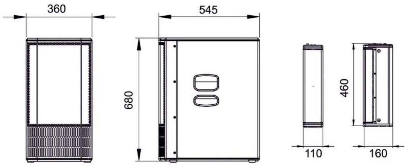
| Subwoofer Dimensions | 360 mm (W) x 680 mm (H) x 545 mm (D) |
| Top Dimensions (each) | 110 mm (W) x 460 mm (H) x 160 mm (D) |
| Subwoofer Weight | 29.3 kg |
| Top Weight (each) | 3.3 kg |
| Power Supply | Mains 100-120V~ or 220-240V~ (interchangeable fuse) |
| Amplifier Power | 1200 W RMS (class D, DIGIPRO G4) |
| Frequency Response | 35 Hz - 20 kHz (-10 dB), 41 Hz - 18 kHz (-6 dB) |
| Maximum SPL | 132 dB at 1 m |
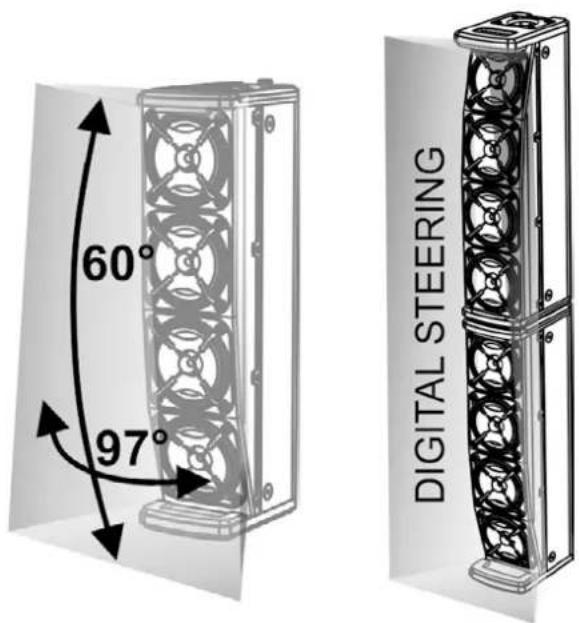
| Directivity (single top) | Horizontal 97°, vertical 60° (asymmetrical) |
| Digital Steering | Sound orientation up, straight, or down (via menu) |
| Audio Inputs | 1 x combo (XLR/Jack) MIC/INSTRUMENT, 2 x combo (XLR/Jack) MIC/LINE |
| Wireless Input | Bluetooth® (stereo) |
| Audio Output | 1 x XLR (AUX/MIX) |
| User Interface | OLED display + rotary encoder (push/turn) |
| Cabinet Material | Plywood |
| Protective Grille | Metal, thickness 1.5 mm, CNC machining |
| Included Accessories | Telescopic pole M20, connecting cables (2.5 m and 2 x 7 m), transport covers, fuse 100-120 V |
| Optional Accessories | Trolley DO-ES212, wall brackets WB-44, aesthetic column DP-ES1203 |
| Safety | Do not remove the front grille; use only the supplied cables; do not obstruct cooling vents |
| Maintenance and Cleaning | Clean with a soft dry cloth; do not use abrasive products or solvents |
| Repairability | Firmware update via USB port (mini-B); technical intervention by authorized service for repair |
| Warranty | Keep proof of purchase; register the product on DB Technologies website |
Frequently Asked Questions - es1203 DB Technologies
User questions about es1203 DB Technologies
0 question about this device. Answer the ones you know or ask your own.
Ask a new question about this device
Download the instructions for your DJ Equipment in PDF format for free! Find your manual es1203 - DB Technologies and take your electronic device back in hand. On this page are published all the documents necessary for the use of your device. es1203 by DB Technologies.
USER MANUAL es1203 DB Technologies
entertainment system

Bluetooth®
USER MANUAL - Section 1
The warnings in this manual must be observed together with the "User Manual - Section 2"
According to the standards EN 55103 this equipment is designed and suitable to operate in E3 (or lower E2, E1) Electromagnetic environments.
FCC CLASS B STATEMENT ACCORDING TO TITLE 47, CHAPTER I, SUBCHAPTER A, PART 15, SUBPART B
This equipment has been tested and found to comply with the limits for a Class B digital device, pursuant to part 15 of the FCC Rules. These limits are designed to provide reasonable protection against harmful interference in a residential installation. This equipment generates, uses and can radiate radio frequency energy and, if not installed and used in accordance with the instructions, may cause harmful interference to radio communications. However, there is no guarantee that interference will not occur in a particular installation. If this equipment does cause harmful interference to radio or television reception, which can be determined by turning the equipment off and on, the user is encouraged to try to correct the interference by one or more of the following measures:
—Reorient or relocate the receiving antenna.
—Increase the separation between the equipment and receiver.
—Connect the equipment into an outlet on a circuit different from that to which the receiver is connected.
—Consult the dealer or an experienced radio/TV technician for help.
Changes or modifications not expressly approved by the party responsible for compliance could void the user's authority to operate the equipment.
ES1203 contains transmitter module FCC ID:QOQWT32I (USA) IC:5123A-BGTWT32I (CANADA)
The Bluetooth ^® word mark and logos are registered trademarks owned by Bluetooth ^® SIG, Inc. and any use of such marks by AEB Industriale SRL is under license. Other Trademarks and trade names are those of their respective owner.
WARNING
Make sure that the loudspeaker is securely installed in a stable position to avoid any injuries or damages to persons or properties. For safety reasons di not place one loudspeaker on top of another without proper fastening systems. Before hanging the loudspeaker check all the components for damages, deformations, missing or damaged parts that may compromise safety during installation. If you use the loudspeakers outdoor avoid spots exposed to bad weather conditions.
Contact dBTechnologies for accessories to be used with the speakers. dBTechnologies will not accept any responsibility for damages caused by inappropriate accessories or additional devices.
ES-1203 Cod. 420120253 REV. 1.0
IMPORTANT SAFETY INSTRUCIONS:
- Read these instructions
- Keep these instructions.
- Heed all warnings.
- Follow all instructions.
- Do not use this apparatus near water.
- Clean only with dry cloth.
- Do not block any ventilation openings. Install in accordance with the manufacturer's instructions.
- Do not install near any heat sources such as radiators, heat registers, stoves, or other apparatus (including amplifiers) that produce heat.
- Do not defeat the safety purpose of the polarized or grounding-type plug. A polarazied plug has two blades with one wider than the other. A grounding type plug has two blades and a third grounding prong. The wide blade or the third prong are provided for your safety. If the provided plug does not fit into your outlet, consult an electrician for replacement of the obsolete outlet.
- Protect the power cord from being walked on or pinched particularly at plugs, convenience receptacles, and the point where they exit from the apparatus.
- Only use attachments/accessories specified by the manufacturer.
- Use only with the cart, stand tripod, bracket, or table specified by the manufacturer, or sold with the apparatus. When a cart is used, use caution, when moving the cart/apparatus combination to hold injury from tip-over.
- Unplug this apparatus during lightning storms or when unused for long periods of time.
- Refer all servicing to qualified service personnel. Servicing is required when the apparatus has benn damaged in any way, such as power-supply cord or plug is damaged, liquid has benn spilled or objects have fallen into the apparatusm the apparatus has been exposed to rain or moisture, does not operate normally, or has been dropped.

WARNING!
- Never remove the product's front protection mesh.
In order to prevent electric shock hazard, in the event of accidental damage or replacement of the protection mesh (which must be carried out by a service center), disconnect the power supply immediately.
Do not connect to the power supply while the mesh has been removed.

ATTENTION!
3. PRIMA ACCENSIONE.... 14
INGRESSI E USCITE 31
text_image
60° 97° DIGITAL STEERINGES-1203 Cod. 420120253 REV. 1.0
text_image
Diagram illustrating a mechanical assembly process with labeled components and directional arrows indicating motion or assembly steps.natural_image
Diagram of a device rear panel with internal circuit board and ports, showing directional arrows (no text or symbols)AMPUFICATORE

text_image
This device consists with part of the ICC tube. Operation is subject to the following two conditions: 1) This device may not cause harmful interference, but and all device reset should be performed. Including interference that may cause undetected operation. Power MAINS FUSE FULL RANGE MAINS INPUT "CAUTION" &I &II &III &IV &V &VI &V &V &V &V &V &V &V &V &V &V &V &V &V &V &V &V &V &V &V &V &V &V &V &V &V &V &V &V &V &V &V &V &V &V1. Balanced Input MIC/INSTRUMENT
2. Balanced Input LINE/MIC (CH.1)
3. Balanced Input LINE/MIC (CH.2)
5. Functions control (Push-rotary encoder)
text_image
This device complies with part 15 of the FCC Rules. Operation is subject to the following two conditions: (1) This device may not cause harmful interference, and (2) this device must accept any interference received, including interference that may cause undesired operation. POWER MAINS FUSE FULL RANGE MAINS INPUT "CAUTION" RISK OF ELECTRICAL SHOCK DO NOT OPEN "ATTENTION" BISQUE DE CHOCN ELECTRIQUE NE PAS OUTVER CE Made in China 12 13 11 10 DESIC & DEVELOPED IN ITALY 9 AEB INDUSTRIALE S.R.L. Via Brodolini, B Località Crispelliano 4083 VALSAMOGGIA (BO) ITALY POWER MAINS FUSE FULL RANGE MAINS INPUT TOP OUTPUTS STEREO (Right) STEREO (Left) MONO 10 DESIC & DEVELOPED IN ITALY9. Left TOP OUTPUT (MONO)
natural_image
Line drawing of a setup with two tall speakers, a central server unit, and a tripod-mounted stand (no text or symbols)C - DOPPIA COLONNA STEREO
natural_image
Technical line drawing of a multi-tiered device labeled 'MONO' (no other text or symbols)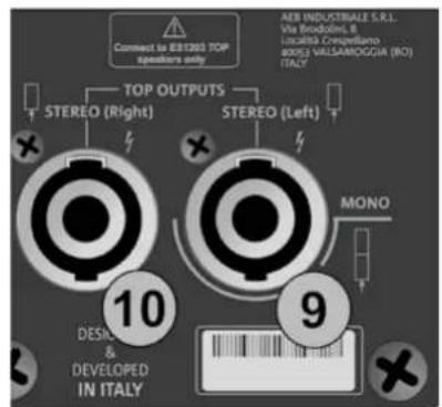
text_image
Connect to IER1200 TOP speakers only TOP OUTPUTS STEREO (Right) STEREO (Left) AER INDUSTRIALE S.R.L. Via Broodini, B Località Cresigliano BOSI VALLAMOGGIA (RO) ITALY 10 DESIGN & DEVELOPED IN ITALY 9 MONO
natural_image
Two identical electrical enclosure units with black cables inserted, shown from different angles (no text or symbols visible)STEREO
text_image
Connect to EBIT203 TDP speakers only TOP OUTPUTS STEREO (Right) STEREO (Left) AEB INDUSTRIALE S.R.L. Via Strodini, 8 Izraelis Cenipollano (ISO) VALSAMOGGIA (NO) ITALY 10 DESIGN & DEVELOPED IN ITALY 9 MONO
ES-1203 Cod. 420120253 REV. 1.0
COLLEGAMENTO DEGLI INGRESSI
PRIMO ESEMPIO
text_image
(1) This device may not cause harmful interference, and (2) this device must accept any interference received, including interference that may cause undesired operation. POWER MAINS FUSE FULL RANGE FAINS INPUT "CAUTION" RISK OF ELECTRICAL SHOCK DO NOT OPEN "ATTENTION" MISQUE DE CHICK ELECTRIQUE NE PAS OUTHER 12 13 11 100-24V~ 50Hz 220-240V~ 2.1A (T6.3A L 250V~) 100-120V~ 4.5A (T10A L 250V~) (REPLACE FUSE WITH SAME RATINGS) (REEMPLACER LE FUSIBLE AVEC LE MIME TYPE) Made in Chinanatural_image
Diagram of two vertical devices connected by a cable, labeled Figura 2 (no text or symbols on devices)text_image
LF +0.0 MF +0.0 Hz 4000 HF +0.0Figura 9
- INPUTS mixer
- OUTPUTS mixer
- AUX mixer
natural_image
Simple line drawing of a simple electrical device connected to a battery (no text or symbols)Figura 12
ES-1203 Cod. 420120253 REV. 1.0
text_image
hnologies 8 Service Data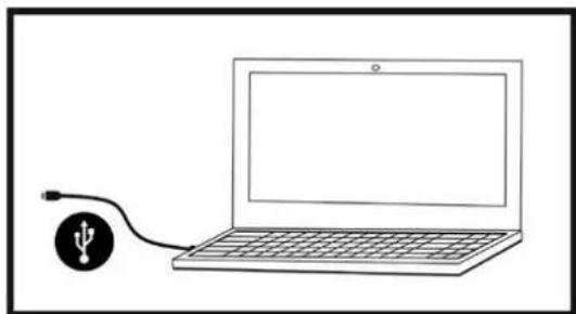
natural_image
Simple line drawing of a laptop connected to a USB symbol (no text or labels)ASSEMBLY (AND DISASSEMBLY) OF TWO TOPS (MONO CONFIGURATION).... 36
ASSEMBLING THE SUPPLIED TELESCOPIC POLE ON THE SUBWOOFER 37
USING THE PROTECTIVE COVERS 37
AMPLIFIER AND CONTROL SECTION FEATURES 38
INPUT, OUTPUT AND CONTROL SECTION 38
AMPLIFIER 38
POWER SUPPLY AND TOP CONNECTION SECTION 38
INPUT, OUTPUT AND CONTROL SECTION 39
POWER SUPPLY AND TOP CONNECTION SECTION 40
2. CONFIGURATION TYPES 41
A-MONO 41
B - STEREO.... 41
C - DOUBLE COLUMN STEREO 41
WALL MOUNTING 41
3. FIRST SWITCH-ON 42
CONNECTING THE TOPS TO THE SUBWOOFER 42
CONNECTING THE INPUTS 43
CONNECTING THE SYSTEM OUTPUT 44
CONNECTING POWER 45
4. HOME PAGE, QUICK CONTROLS, MIXER 46
-
EXTENDED SETTINGS MENU 50
-
ACCESSORIES.... 55
-
TROUBLESHOOTING 56
-
UPDATING THE FIRMWARE 57
9. TECHNICAL SPECIFICATIONS 58
GENERAL 58
ACOUSTIC DATA 58
AMPLIFIER 58
OPERATING TEMPERATURE.... 59
PROCESSOR 59
USER INTERFACE 59
INPUTS AND OUTPUTS.... 59
POWER SUPPLY SPECIFICATIONS (CONSUMPTION / INSTALLATION) 59
DIMENSIONS.... 60
1. GENERAL INFORMATION
WELCOME!
Thanks for purchasing a product that was designed and developed in Italy by dBTechnologies! This active, versatile and ergonomic system is the result of long experience in the field of sound diffusion. It uses optimised acoustic and electronic solutions as well as an optimal choice of materials.
INTRODUCTORY OVERVIEW
The ES 1203 is the top of the ES range. The acoustic design provides two tops with 4 x 4" mid-woofers each, with a "Logarithmic Curved Array" profile and phase plugs to optimise the acoustic coverage. Together with the powerful wooden subwoofer, equipped with 2 x 12" woofers, this design choice can achieve impressive sonic accuracy and depth for such a compact system.
Its versatility for both indoor and outdoor use is ensured by a generous array of inputs (including Bluetooth ^® ), by the possibility of cascading a second system and by the various parameters that can be configured through the OLED interface.
Various accessories are included in the package and others help with handling (DO-ES212 trolley) and use in a fixed installation (WB-44 wall brackets). The most important features are:
- compact high-quality system that is easy to transport, with the following configurations: MONO, STEREO, DOUBLE COLUMN (when used with a second system)
- optimised acoustic solutions to ensure excellent sound quality over a wide frequency range and perfect speech intelligibility
- new generation DIGIPRO G4 digital amplifier (1200 W RMS) with PFC.
- 1 MIC/INSTRUMENT input, 2 LINE/MIC inputs (stereo configuration), Bluetooth® connection
- OLED display and compact interface with rotary button for full system configuration.
PACKAGE CONTENTS
• 1 ES1203SUB subwoofer and 2 ES1203TOP tops
• 1 mountable telescopic pole (M20 threaded end)
- 3 cables for connecting the tops to the subwoofer (2 x 7 m for the stereo configuration, 1 x 2.5 m for the mono configuration) and 4 clips to organise the cabling
- 2 covers, which can be coupled, for transporting the system, cables and pole
- fuse for operation at 100-120 V\~
- power cable
- documentation
USER INFORMATION
To use your ES-1203 system in the best way, we recommend that you:
- read the quick start user manual in the package and all of this full user manual, and keep it for the whole life of the product.
- register the product in the "SUPPORT" section at http://www.dbtechnologies.com.
- keep proof of purchase and the WARRANTY (User manual "section 2").
ES-1203 Cod. 420120253 REV. 1.0
MECHANICAL AND ACOUSTIC FEATURES
DIMENSIONS
The measurements of the ES1203 system are:
SUBWOOFER: 360 mm x 680 mm x 545 mm
TOP: 110 mm x 460 mm x 160 mm
ACOUSTIC COVERAGE
The acoustic coverage of a single ES1203 top is 60° (vertical) and 97° (horizontal). The coverage is asymmetrical.
When the two tops are mounted one on top of the other (see the related section), you can use digital steering to direct the coverage upwards or downwards (selectable through the user interface).
ES-1203 Cod. 420120253 REV. 1.0
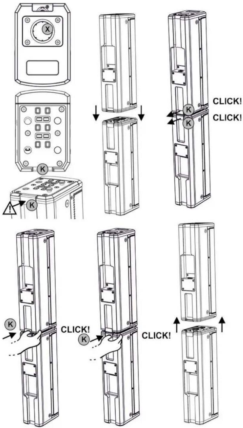
ASSEMBLY (AND DISASSEMBLY) OF TWO TOPS (MONO CONFIGURATION)
In the mono configuration, you must assemble the two tops (ES1203TOP) with one on top of the other.
Each top features two sides.
One side has a 36 mm diameter hole [X] for inserting the pole.
The other side has a locking system with a rear safety lever [K].

CAUTION!
- BEFORE ASSEMBLY, MAKE SURE THAT THE SAFETY LEVERS [K] ARE PUSHED INWARDS AND NOT IN THE RELEASED POSITION (OUTWARDS).
- Flip one of the two tops as shown in the figure
- Place one of the two tops on the other with the two locking systems aligned
- Apply pressure so that the two locking systems engage. When they are assembled correctly, the two rear safety levers [K] move outwards (released position) and each makes a "click".
To disassemble the two tops:
- Press the two rear safety levers
- Remove the two tops
text_image
X K K K K CLICK! CLICK! K K CLICK!ES-1203 Cod. 420120253 REV. 1.0
ASSEMBLING THE SUPPLIED TELESCOPIC POLE ON THE SUBWOOFER
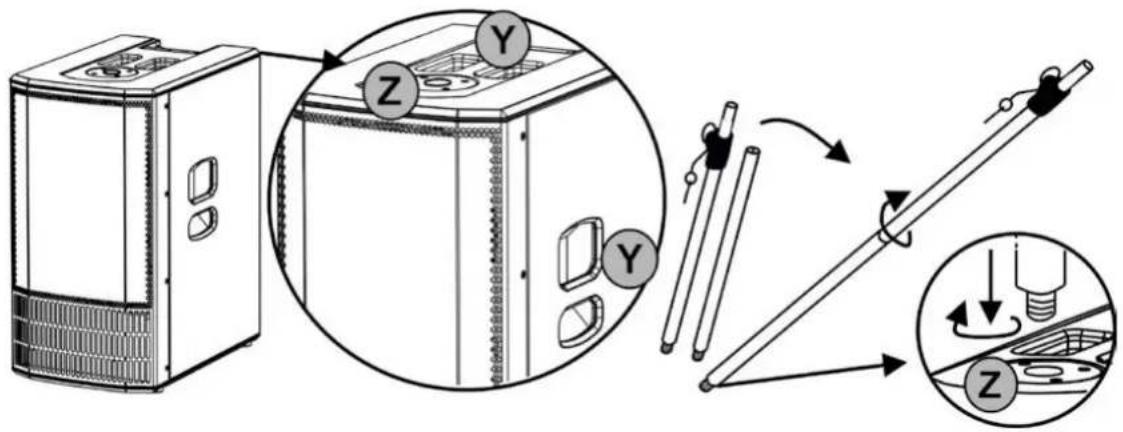
text_image
Diagram illustrating a device assembly process with labeled components and directional arrows indicating motion or assembly steps.The subwoofer (ES1203 SUB) has three transport handles [Y]: Two on the sides and one at the top. There is also an M20 threaded hole [Z] in the top for inserting the telescopic pole provided. To assemble the telescopic pole:
- Screw the top (telescopic) part onto the lower (fixed) part with a clockwise movement
- Screw the resulting pole into the hole [Z] with a clockwise movement
Insert the adjustable pole into the hole [X] on a single top, or on a double top in the MONO configuration.
Refer to chapter 2, CONFIGURATION TYPES, for further information and for the maximum allowed installation heights.
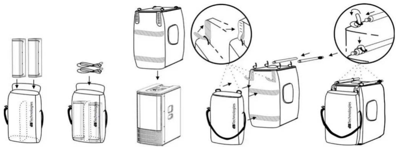
USING THE PROTECTIVE COVERS
flowchart
graph TD
    A["Device Packaging"] --> B["Assembly"]
    B --> C["Internal Components"]
    C --> D["Product Packaging"]
    D --> E["Final Packaging"]

    subgraph Component 1
        F["Device Packaging"] --> G["Assembly"]
        G --> H["Internal Components"]
        H --> I["Product Packaging"]
    end

    subgraph Component 2
        J["Device Packaging"] --> K["Assembly"]
        K --> L["Internal Components"]
        L --> M["Product Packaging"]
    end

    subgraph Component 3
        N["Device Packaging"] --> O["Assembly"]
        O --> P["Internal Components"]
        P --> Q["Product Packaging"]
    end

    subgraph Component 4
        R["Device Packaging"] --> S["Assembly"]
        S --> T["Internal Components"]
        T --> U["Product Packaging"]
    end

    subgraph Component 5
        V["Device Packaging"] --> W["Assembly"]
        W --> X["Internal Components"]
        X --> Y["Product Packaging"]
    end

    subgraph Component 6
        Z["Device Packaging"] --> AA["Assembly"]
        AA --> AB["Internal Components"]
        AB --> AC["Product Packaging"]
    end

    subgraph Component 7
        AD["Device Packaging"] --> AE["Assembly"]
        AE --> AF["Internal Components"]
        AF --> AG["Product Packaging"]
    end

    subgraph Component 8
        AH["Device Packaging"] --> AI["Assembly"]
        AI --> AJ["Internal Components"]
        AJ --> AK["Product Packaging"]
    end

    subgraph Component 9
        AL["Device Packaging"] --> AM["Assembly"]
        AM --> AN["Internal Components"]
        AN --> AO["Product Packaging"]
    end

    subgraph Component 10
        AP["Device Packaging"] --> AQ["Assembly"]
        AQ --> AR["Internal Components"]
        AR --> AS["Product Packaging"]
    end

    subgraph Component 11
        AT["Device Packaging"] --> AU["Assembly"]
        AU --> AV["Internal Components"]
        AV --> AW["Product Packaging"]
    end

    subgraph Component 12
        AX["Device Packaging"] --> AY["Assembly"]
        AY --> AZ["Internal Components"]
        AZ --> BA["Product Packaging"]
    end

    subgraph Component 13
        BB["Device Packaging"] --> BC["Assembly"]
        BC --> BD["Internal Components"]
        BD --> BE["Product Packaging"]
    end

    subgraph Component 14
        BF["Device Packaging"] --> BG["Assembly"]
        BG --> BH["Internal Components"]
        BH --> BI["Product Packaging"]
    end

    subgraph Component 15
        BJ["Device Packaging"] --> BK["Assembly"]
        BK --> BL["Internal Components"]
        BL --> BM["Product Packaging"]
    end

    subgraph Component 16
        BN["Device Packaging"] --> BO["Assembly"]
        BO --> BP["Internal Components"]
        BP --> BQ["Product Packaging"]
    end

    subgraph Component 17
        BR["Device Packaging"] --> BS["Assembly"]
        BS --> BT["Internal Components"]
        BT --> BU["Product Packaging"]
    end

    subgraph Component 18
        BV["Device Packaging"] --> BW["Assembly"]
        BW --> BX["Internal Components"]
        BX --> BY["Product Packaging"]
    end

    subgraph Component 19
        BZ["Device Packaging"] --> CA["Assembly"]
        CA --> CB["Internal Components"]
        CB --> CC["Product Packaging"]
    end

    subgraph Component 20
        DB["Device Packaging"] --> DC["Assembly"]
        DC --> DD["Internal Components"]
        DD --> DE["Product Packaging"]
Two protective bags are provided. To protect the system:
- Put the two tops and the cables into the smaller cover. Note that you can transport them separately, thanks to the shoulder strap
- Put the larger cover over the subwoofer from above
- Attach the two covers together using the Velcro bands as shown. Two bands are at the back of the two covers, thread the two smaller bands through the eyelets on the cover with the tops in it
- Put the two parts of the telescopic pole into the four eyelets at the top of the subwoofer cover and adjust the straps
ES-1203 Cod. 420120253 REV. 1.0
AMPLIFIER AND CONTROL SECTION FEATURES
The core of the ES range is the class-D digital amplifier. The system is silent and is controlled by a dedicated powerful DSP that manages various parameters. These are completely configurable, thanks to the control interface. The amplifier power is 1200 W RMS.
The ES1203 panel features:
- Input, Output and Control section
• Power supply and Top connection section

CAUTION!
- Do not obstruct the amplifier cooling fins at the back. In the event of overheating, the audio volume is gradually reduced until the module is thermally stable. The level is automatically restored on reaching the correct operating temperature.
- Do not attempt to open the amplifier.
- In the event of malfunction, immediately turn off the power, disconnect the module from the mains and contact an authorised repairer.
- Only use the cables provided.
-
The system comes with a fuse already fitted for operation in the 220 - 240 V range. If you need to operate it in the 100-120 V range:
-
Disconnect all connections, including the power supply.
- Wait for 5 minutes.
- Replace the fuse with the one supplied in the package for the 100-120 V range.

CAUTION!
- Never remove the protective grille from the front of the product. To prevent an electric shock hazard, immediately disconnect the power supply in the event of accidental damage or when replacing the protective grille (to be done by the assistance service). Never connect the mains power with the grille removed.
text_image
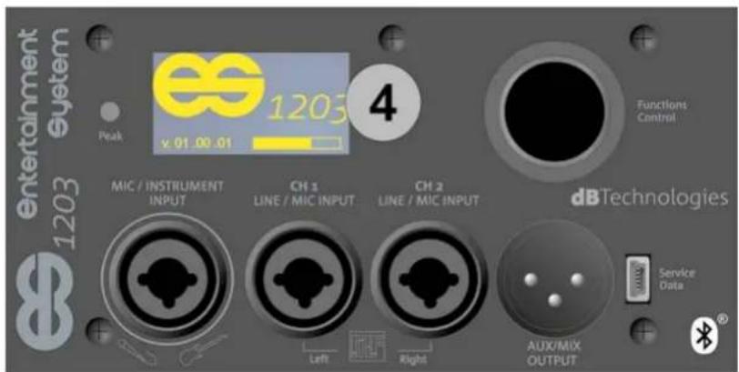
Entertainment System 1203 Pegal MIC / INSTRUMENT INPUT CH 4 LINE / MIC INPUT CH 2 LINE / MIC INPUT dBTechnologies Service Delta LAN Right AUX/MIX OUTPUTINPUT, OUTPUT AND
CONTROL SECTION
natural_image
Diagram of a computer monitor case with internal circuit board and ventilation slots (no text or labels)AMPLIFIER
text_image
This device compares with part to of the FCC Rule. Operation is subject to the following key conditions: (1) This device may not cause transverse interference, and (2) This device should be found instead of using a single component. Including interference that may issue undetected operation. POWER MAINS FUSE FULL RANGE MAINS INPUT CAUTION MINI MINI MINI MINI STEREO (Right) STEREO (Left) MONO DESIGNED DEVELOPED IN ITALY 300-240V* 50-60Hz 300-240V* 8.5A TIL 3.5-5.5pV* 300-240V* 8.5A (Tollb L 250V*) MODE TO CHINA MOMO Connected to ENTER STOP operations ring TOP OUTPUTS STEREO (Right) STEREO (Left) MINI MINI MINI MINI MINI MINI MINI MINIPOWER SUPPLY AND
TOP CONNECTION
SECTION
ES-1203 Cod. 420120253 REV. 1.0
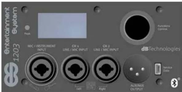
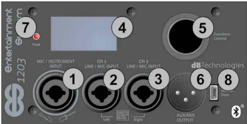
INPUT, OUTPUT AND CONTROL SECTION
text_image
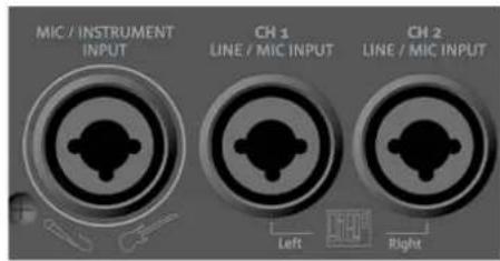
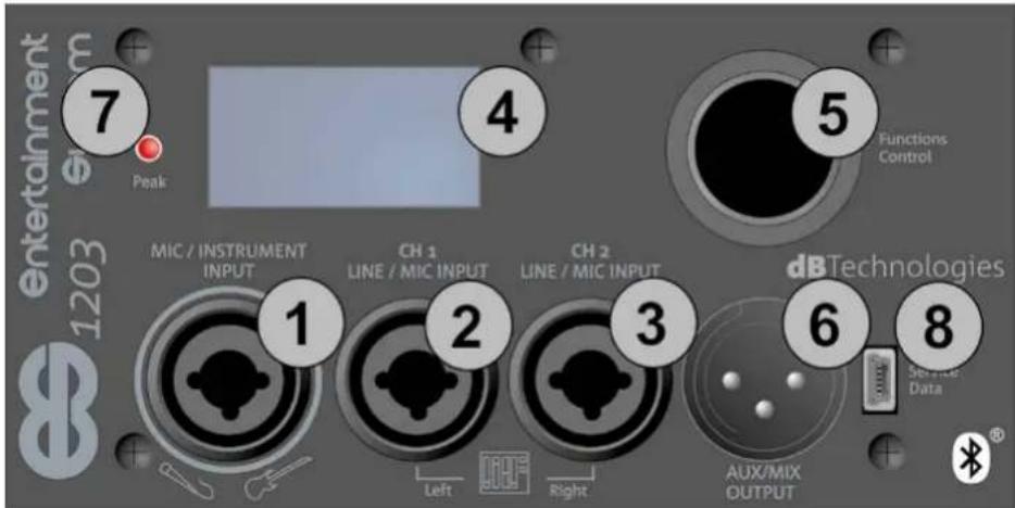
Entertainment 1203 Peak 7 4 5 Functions Control MIC / INSTRUMENT INPUT CH 1 LINE / MIC INPUT CH 2 LINE / MIC INPUT dB Technologies Service Data 1 2 3 6 8 Left Right AUX/MIX OUTPUT1. Balanced MIC/INSTRUMENT Input
This is an XLR or TRS (balanced or unbalanced) combo connector input.
It allows you to connect a microphone or instrument with a high output impedance (e.g. a guitar). See chapters 4 and 5 for details of the channel settings.
2. Balanced LINE/MIC Input (CH.1)
This is an XLR or TRS (balanced or unbalanced) combo connector input.
It allows you to connect a microphone or line signal (e.g. from a mixer or instrument with a line output impedance, such as an electronic keyboard).
It can function as a mono channel, or as the left channel in a stereo input connection, when used together with input [3]. See chapters 4 and 5 for details of the channel settings.
3. Balanced LINE/MIC Input (CH.2)
This is an XLR or TRS (balanced or unbalanced) combo connector input.
It allows you to connect a microphone or line signal (e.g. from a mixer or instrument with a line output impedance, such as an electronic keyboard).
It can function as a mono channel, or as the right channel in a stereo input connection, when used together with input [2]. See chapters 4 and 5 for details of the channel settings.
4. OLED Screen
This screen displays all the control settings and configurable system settings.
5. Functions control (Push-rotary encoder)
This push-rotary button selects or confirms a parameter, or passes from one screen to another (shortcut) when browsing the system menu.
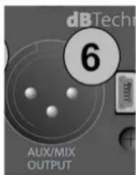
6. Aux/Mix Output
This is an XLR connector output.
It allows you to send the system total output signal (AUX) to a second speaker.
Alternatively, it allows you to send the appropriate channel (MIX: left or right) to a second ES1203 system to create a DOUBLE COLUMN configuration. See chapter 3 for further details.
7. "PEAK" LED
This lights to indicate when the amplifier protection circuit has intervened. Avoid using an input level that makes this circuit intervene too often.
8. "Service/Data" USB PORT
This is a mini type-B USB port to be used exclusively for updating the firmware. See the related section.
ES-1203 Cod. 420120253 REV. 1.0
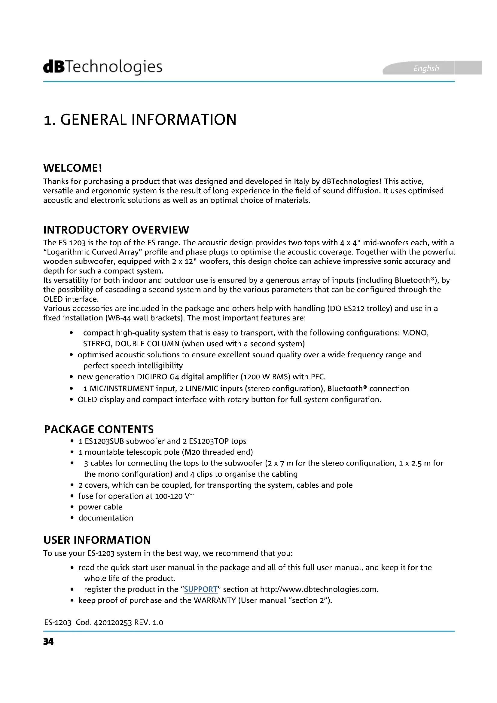
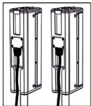
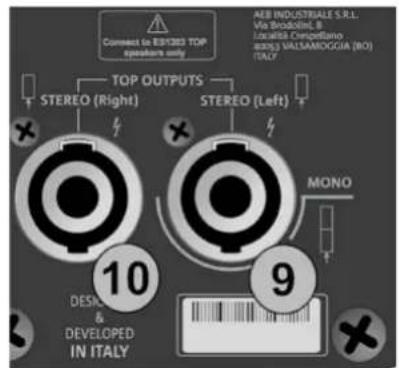
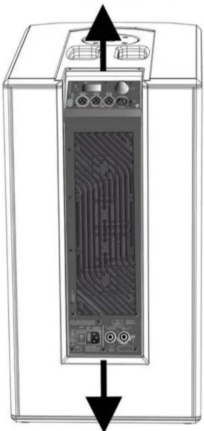
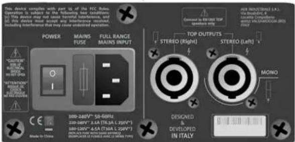
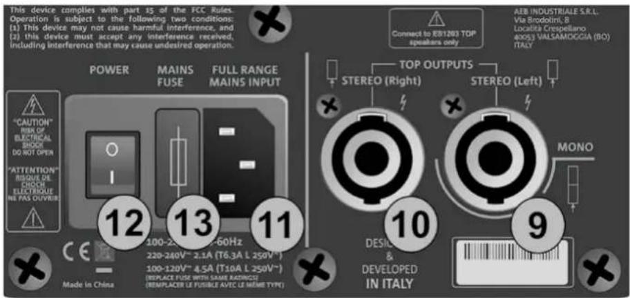
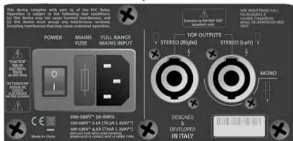
POWER SUPPLY AND TOP CONNECTION SECTION
text_image
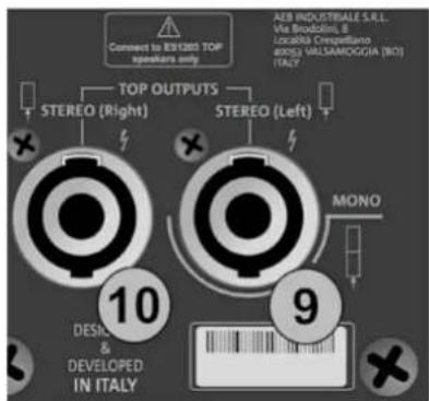
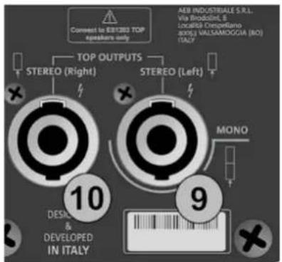
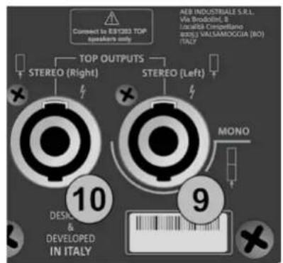
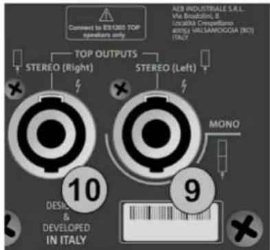
This device complies with part 15 of the FCC Rules. Operation is subject to the following two conditions: (1) This device may not cause harmful interference, and (2) this device must accept any interference received, including interference that may cause undesired operation. POWER MAINS FUSE FULL RANGE MAINS INPUT "CAUTION" RISK OF ELECTRICAL SHOCK DO NOT OPEN "ATTENTION" BISQUE DE CHOCH ELECTRIQUE NE PAS OLIVIER 12 13 11 Made in China 100-2.0V~ 60Hz 220-240V~ 2.1A (T6.3A L 250V ~) 100-120V~ 4.5A (T10A L 250V ~) (REPLACE FUSE WITH SAME RADIUS) (REPLACER LE FUSIBLE AVEC LE MÊME TYPE) Connect to KB1203 TOP speakers only TOP OUTPUTS STEREO (Right) STEREO (Left) MONO DESICIL & DEVELOPED IN ITALY AEB INDUSTRIALE S.R.L. Via Broodolini, B Località Crespellano 40053 VALSAMOGGIA (BO) ITALY X9. Left TOP OUTPUT (MONO)
This connector is for connecting a top (left) in the STEREO configuration, or for connecting the double top in the mono configuration.
10. Right TOP OUTPUT
This connector is for connecting a top (right) in the STEREO configuration.
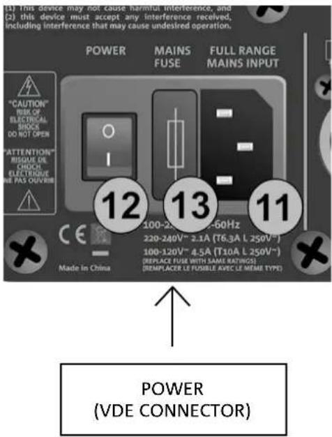
11. MAINS INPUT
This is a VDE connector input. It is for connecting the power line, using the cable provided.
12. ON-OFF SWITCH
This switch turns the system on ("I" position) or off ("O" position)
13. MAINS FUSE
This is the mains fuse holder (replaceable when blown or for operation in the 100-120 V\~ range)

CAUTION!
- Connect only ES1203TOP passive diffusers to the TOP OUTPUTS connectors!
ES-1203 Cod. 420120253 REV. 1.0
2. CONFIGURATION TYPES

• Installation types other than those illustrated here are not allowed.
- Never hang the subwoofer by its handles
- Always check that placement is stable and the installation is not a hazard to people, animals or things.
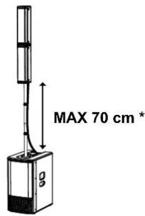
A - MONO
In the MONO configuration, the double head is mounted on the subwoofer using a telescopic pole with adjustable height.

CAUTION!
- In this configuration, if the distance from the top of the subwoofer to the bottom of the lower top is greater than 70 cm, you must also anchor the system to the ground with straps and suitable mechanical means (not supplied).
text_image
MAX 70 cm *B - STEREO
In the STEREO configuration, use two tripods with a 35 mm diameter pole (SK36 TT kit accessory) as shown in the figure.
natural_image
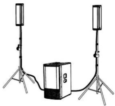
Illustration of two tall-mounted devices connected to a central server unit, with no visible text or symbols.C - DOUBLE COLUMN STEREO
In the DOUBLE COLUMN STEREO configuration, use two MONO systems connected together as explained in the CONNECTING THE OUTPUT FROM ONE SYSTEM TO ANOTHER paragraph.

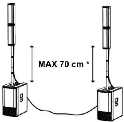
CAUTION!
- In this configuration, if the distance from the top of the subwoofer to the bottom of the lower top is greater than 70 cm, you must also anchor the system to the ground with straps and suitable mechanical means (not supplied).
text_image
MAX 70 cm *WALL MOUNTING
For each of the configuration types A, B or C illustrated above, you can use the optional WB-44 (wall mounting brackets kit) accessory to mount the system tops on the wall as part of a fixed installation.
See the ACCESSORIES chapter for further information.
ES-1203 Cod. 420120253 REV. 1.0
3. FIRST SWITCH-ON
CONNECTING THE TOPS TO THE SUBWOOFER
MONO CONFIGURATION
When using a MONO configuration, mount the two heads as described in the related paragraph and then you only need one connection from the subwoofer to one of the two tops:
- Insert the double top onto the telescopic pole mounted previously on the subwoofer (it makes no difference whether you choose hole [X] or the other one)
- Use the 2.5 m cable provided.
- Connect the bottom connector on the double top as shown
- Connect it to the MONO connector [9] on the sub
- Use the clips provided to secure the cable to the telescopic pole

natural_image
Technical line drawing of a multi-tiered device labeled 'MONO' (no other text or symbols)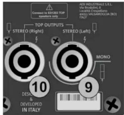
text_image
Connect to ER1283 TOP speakers only TOP OUTPUTS STEREO (Right) STEREO (Left) AER INDUSTRIALE S.R.L. Via Broodine, B LocalBIS Cesqueillane 40051 VALSAMDOGGIA (NO) ITALY 10 DESIGN & DEVELOPED IN ITALY 9 MONO
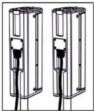
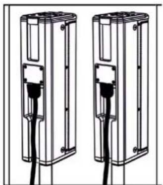
- Insert each top onto its own pole (e.g. using the SK 36 TT kit)
- Use the two 7 m cables provided.
- Connect each top as shown
- Connect the left cable connector [9] and the right cable connector [10] to the subwoofer.
- Use the clips provided to secure the cables to the telescopic poles
natural_image
Two identical mechanical components with black connectors and a central connector, shown side by side (no text or symbols)STEREO
text_image
Connect to 8/1200 TOP speakers only TOP OUTPUTS STEREO (Right) STEREO (Left) AEB INDUSTRIALE S.R.L. Via Brodolini, B. Località Crespelliano 6005) VALLSAMOGGIA (N1) ITALY 10 DESIGN & DEVELOPED IN ITALY 9 MONO
ES-1203 Cod. 420120253 REV. 1.0
CONNECTING THE INPUTS
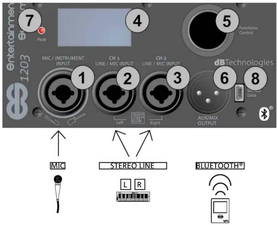
FIRST EXAMPLE
- Connect a microphone to connector [1]
- Connect a stereo source (e.g. a keyboard or mixer) to the two channels [2] and [3]. The left output channel from the source should be connected to CH1 [2], and the right channel to CH2 [3].
- Enable Bluetooth® transmission on a multimedia device (e.g. MP3 player)
- To set the input type (MIC/INSTRUMENT or LINE/MIC) and adjust the levels and parameters, refer to chapter 3: HOME PAGE, QUICK CONTROLS, MIXER.
SECOND EXAMPLE
- Connect an instrument with a high output impedance (e.g. a guitar) to connector [1].
- Connect a microphone to connector [2].
- Connect the mono output of an instrument with a line output (such as a keyboard) to connector [3].
- Enable Bluetooth® transmission on a multimedia device (e.g. MP3 player).
- To set the input type (MIC/INSTRUMENT or LINE/MIC) and adjust the levels and parameters, refer to chapter 4: HOME PAGE, QUICK CONTROLS, MIXER.
text_image
entertainmen 1203 7 Peak 4 5 Functions Control MIC / INSTRUMENT INPUT CH 1 LINE / MIC INPUT CH 2 LINE / MIC INPUT dB Technologies Service Data 1 2 3 6 8 Left Right AUX/MIX OUTPUT MIC STEREO LINE L R BLUETOOTH®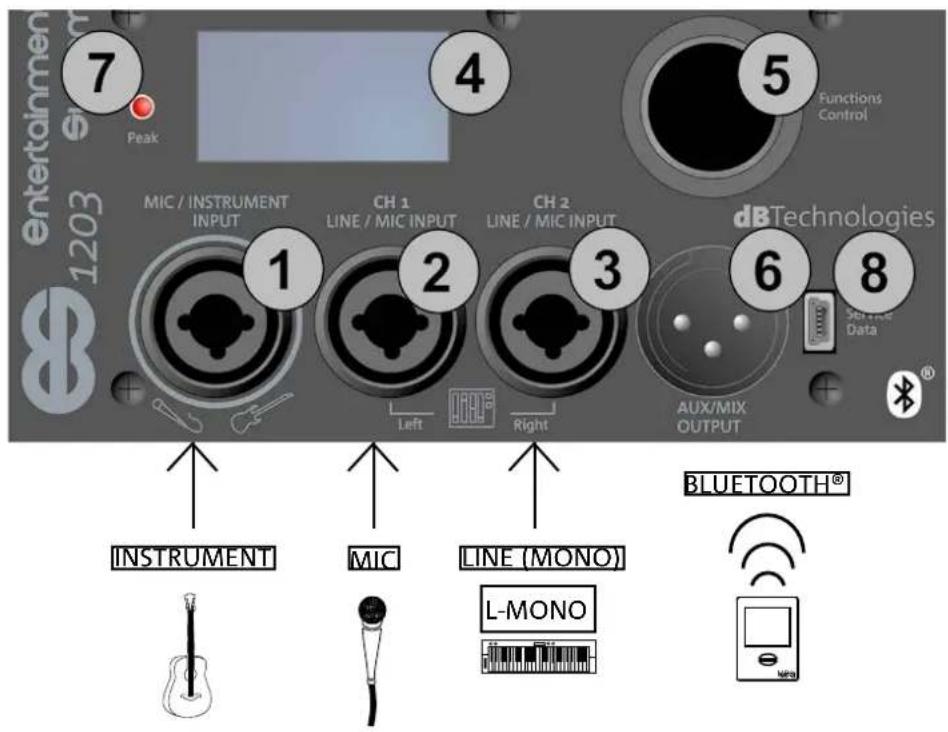
text_image
Entertainmen 1203 7 Peak 4 5 Functions Control MIC / INSTRUMENT INPUT CH 1 LINE / MIC INPUT CH 2 LINE / MIC INPUT dB Technologies Set time Data 1 2 3 6 8 Left Right AUX/MIX OUTPUT INSTRUMENT MIC LINE (MONO) BLUETOOTH® L-MONOES-1203 Cod. 420120253 REV. 1.0
CONNECTING THE SYSTEM OUTPUT
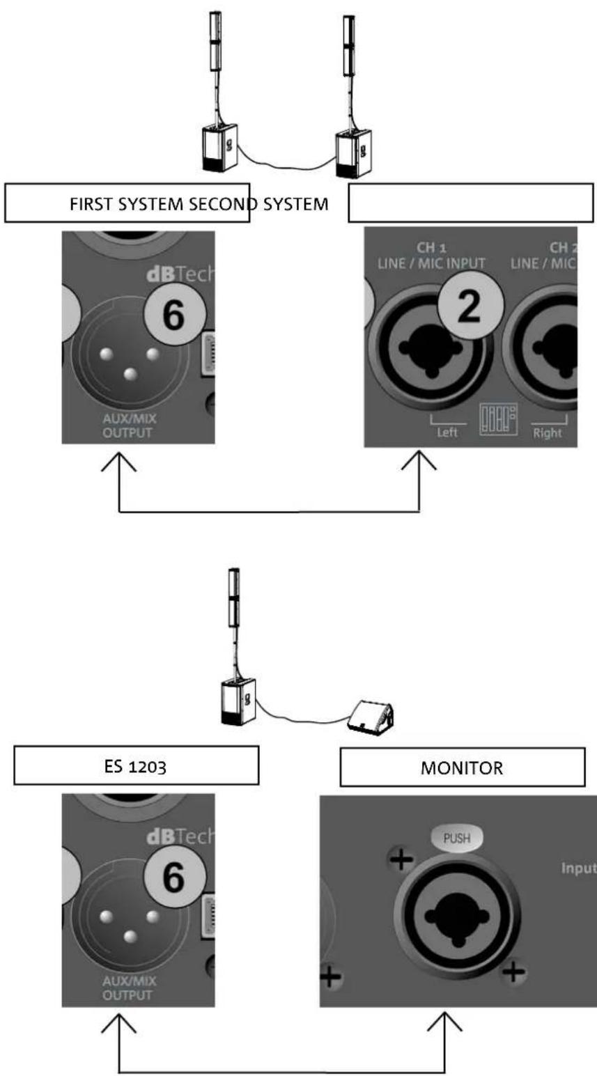
DOUBLE COLUMN STEREO CONFIGURATION (MIX)
To send the audio to a second ES1203 system (DOUBLE COLUMN configuration):
- Connect output connector [6] on the first ES1203 to the CH1 Left input [2]
- To set stereo operation (left and right) and the output levels and parameters, refer to chapter 4: QUICK AND MIXER CONTROLS.
OUTPUT (AUX)
To send the audio to another amplified diffuser:
- Connect output connector [6] on the first ES1203 to the Input on the second amplified diffuser.
• To set the levels and parameters, refer to chapter 4: QUICK AND MIXER CONTROLS.
flowchart
graph TD
    A["First System Second System"] --> B["ES 1203"]
    B --> C["MONITOR"]
    C --> D["Output"]
    style A fill:#f9f,stroke:#333
    style B fill:#ccf,stroke:#333
    style C fill:#cfc,stroke:#333
ES-1203 Cod. 420120253 REV. 1.0
CONNECTING POWER
- Insert the VDE connector of the provided cable into the "MAINS INPUT" [11].
- Insert the plug into a power socket with an earth conductor.
- Press the POWER switch [12] to the "I" position.
• The OLED screen [4] will light up. - The system will take a few seconds to load the firmware and any saved user settings. The current firmware version will be shown in the start page and a bar will show the loading progress.
text_image
(1) this device may not cause harmful interference, and (2) this device must accept any interference received, including interference that may cause undesired operation. POWER MAINS FUSE FULL RANGE FAINS INPUT "CAUTION" RISK OF ELECTRICAL SHOCK DO NOT OPEN "ATTENTION" RESUSE DE CHICK ELECTRIOUE WE PAS OUTRUN 12 13 11 100-25V~ 60Hz 220-240V~ 2.1A (T6.3A L 250V~) 100-120V~ 4.5A (T10A L 250V~) (REPLACE FUSE WITH SAME RATINGS) (REPLACE LE FUABLE AVEC LE MEMI TYPE) Made in China POWER (VDE CONNECTOR)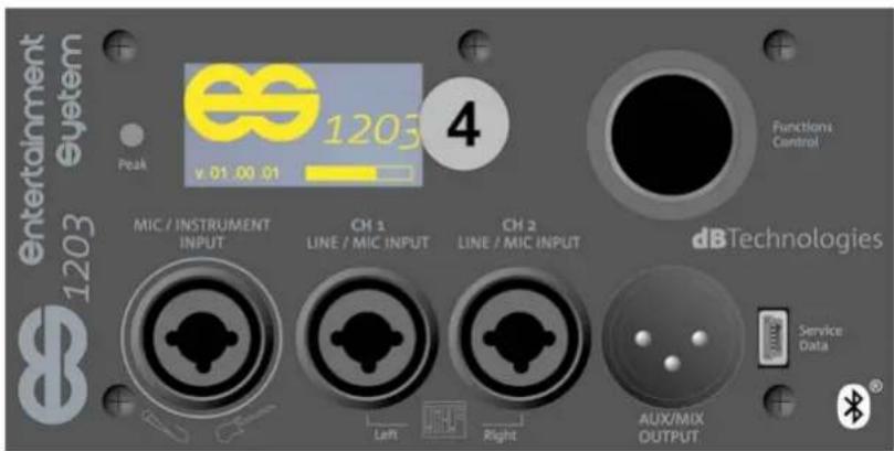
text_image
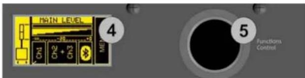
entertainment 1203 System Peak v.01.00.01 4 Functions Control MIC / INSTRUMENT INPUT CH 1 LINE / MIC INPUT CH 2 LINE / MIC INPUT dBTechnologies Service Data Aux/MIX OUTPUT4. HOME PAGE, QUICK CONTROLS, MIXER
text_image
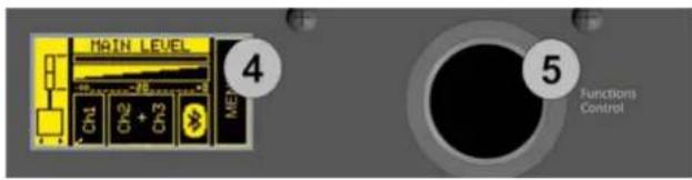
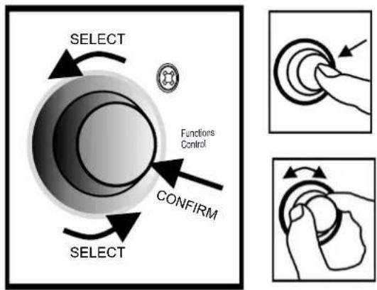
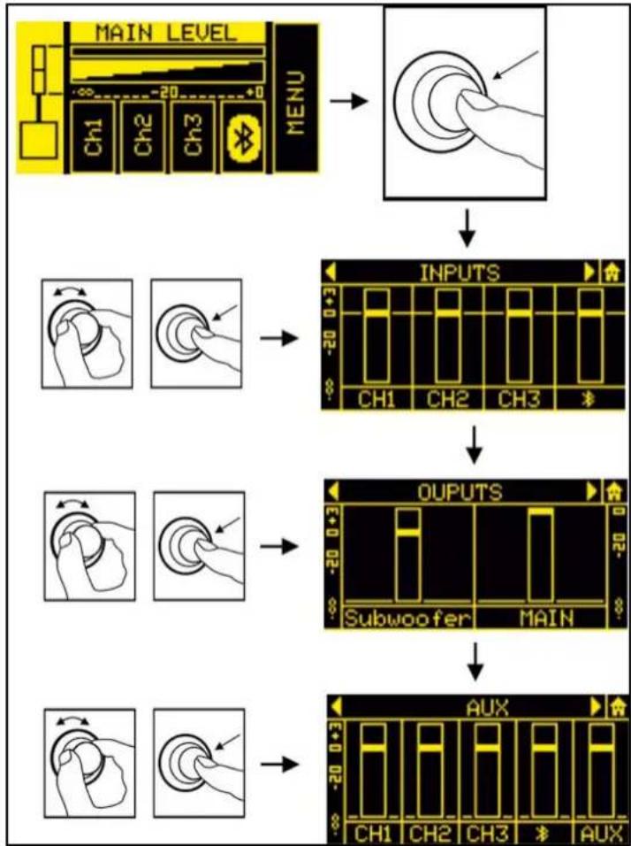
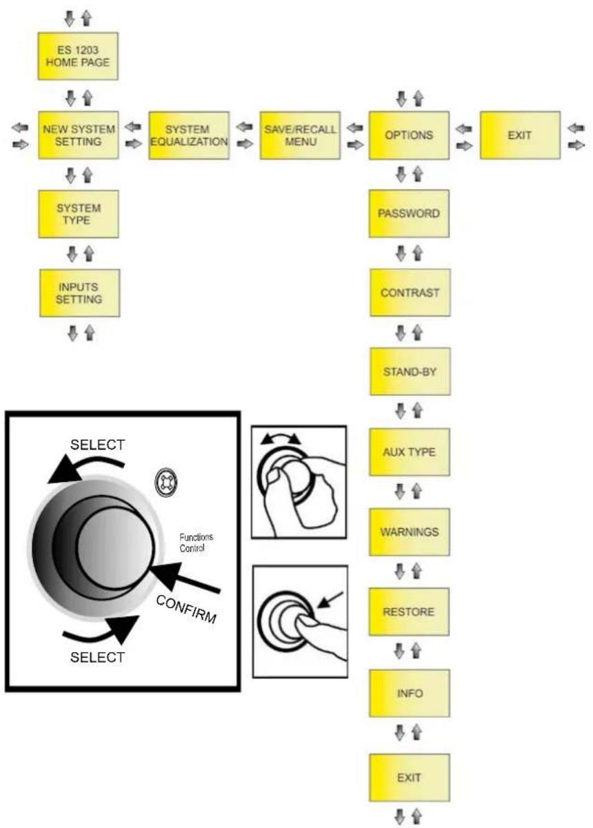
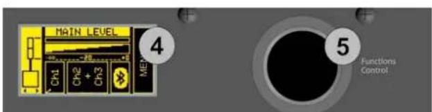
MAIN LEVEL 4 CH1 CH2 + CH3 ME 5 Functions ControlYou can view and configure the various ES1203 system parameters using the OLED screen [4] and the rotary button [5] in the Functions Control section.
Pressing [5] selects and confirms a page or parameter. Pressing it for a few seconds jumps to other pages (shortcut).
Turning it lets you browse the various pages or, if you are in the parameters on a page, increase or decrease the selected value.
flowchart
graph TD
    A["SELECT"] --> B["Functions Control"]
    B --> C["CONFIRM"]
    C --> D["SELECT"]
    style A fill:#f9f,stroke:#333
    style B fill:#ccf,stroke:#333
    style C fill:#cfc,stroke:#333
    style D fill:#fcc,stroke:#333
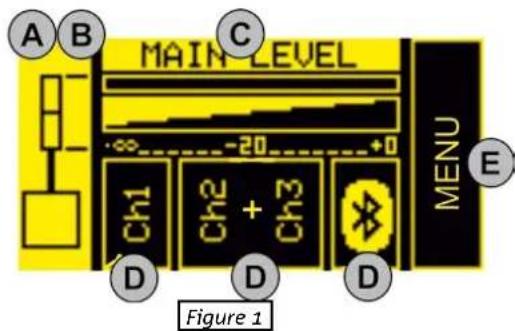
HOME PAGE AND QUICK CONTROLS
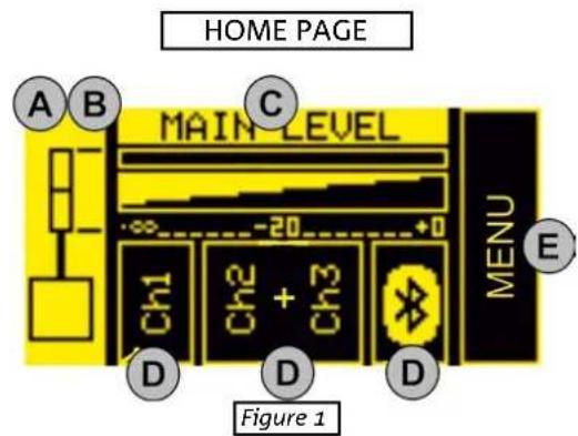
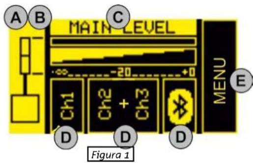
You can perform the following basic operations from the HOME page (figure 1):
A. set the configuration type
B. select the digital steering (coverage angle)
C. set the MAIN LEVEL system volume
D. access the input configuration pages
E. access the extended MENU (see the EXTENDED SETTINGS MENU chapter)
From this page, you can use a shortcut to access the system mixers (see the INPUT, OUTPUT AND AUX MIXERS paragraph).

In the DOUBLE COLUMN STEREO configuration (figure 2), each individual ES1203 is identified as the right or left Master or Slave. There must be one Master and one Slave. Master means the ES1203 system to which the inputs are connected and on which you set up all the adjustments, which will consequently control the Slave system. Therefore, adjustments will be disabled on the Slave system.
text_image
HOME PAGE A B C MAIN LEVEL MENU E Ch1 Ch2 + Ch3 D D D Figure 1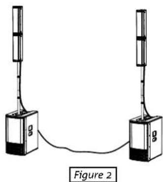
natural_image
Simple line drawing of two vertical devices connected by a cable, labeled Figure 2 (no text or symbols on devices)Lets see the steps listed above in detail:
A. use [5] to select the left box (figure 1) and highlight it. Confirm and turn to select the appropriate configuration. You can set the ES1203 system as:
- MONO
• STEREO
• DOUBLE COLUMN STEREO MASTER LEFT (ML)
• DOUBLE COLUMN STEREO SLAVE LEFT (SL)
• DOUBLE COLUMN STEREO MASTER RIGHT (MR)
• DOUBLE COLUMN STEREO SLAVE RIGHT (SR)
ES-1203 Cod. 420120253 REV. 1.0
B. You can change the digital steering of the tops by selecting and pressing [5] after you have confirmed a MONO or DOUBLE COLUMN STEREO configuration, choosing from:
- UP (upwards)
- FAR (no angle)
- DOWN (downwards)
Press [5] again to confirm your chosen option (e.g. figure 3)

While choosing the configuration, left and right arrows appear under the system diagram.
While choosing the steering, up and down arrows appear under the system diagram.

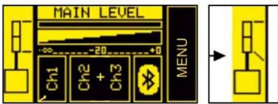
C. Select and confirm MAIN LEVEL (figure 4) to increase or decrease the overall ES1203 system volume.
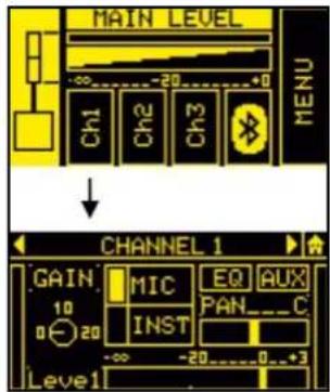
D. Select and confirm the desired input to access the corresponding sub page. The available inputs are:
- CH1
- CH2
- CH3
- BLUETOOTH®

The CH2 and CH3 inputs are initially set as a single stereo channel (L+R). Once you have accessed the sub page, you can use them as two separate mono channels by selecting the input type.
The table below shows the adjustable parameters for inputs CH1, CH2 and CH3:
text_image
MAIN LEVEL Ch1 Ch2 + Ch3 MENUFigure 3

Figure 4
text_image
MIC / INSTRUMENT INPUT CH 1 LINE / MIC INPUT CH 2 LINE / MIC INPUT Left RightFigure 5
text_image
MAIN LEVEL Ch1 Ch2 Ch3 MENU ↓ CHANNEL 1 GAIN MIC EQ AUX 10 INST PAN_C 0 20 -∞ -20 0 3 Level1Figure 6
| NAME PARAMETER RANGE | ||
| GAIN | INPUT GAIN [0, 10, 20] dB | |
| LEVEL | OUTPUT LEVEL (SENT TO THE INTERNAL MIXER) -∞ ÷ 3 dB | |
| TYPE | INPUT TYPE | CH1: MIC/INST - CH2, CH3:MIC/LINE |
| EQ | FILTERS THAT CAN BE APPLIED TO MICROPHONE, INSTRUMENT OR LINE INPUTS | SEE THE TABLE ON PAG. 48 |
| AUX | AUXILIARY SEND MIXER (NOT AVAILABLE IN THE DOUBLE COLUMN CONFIGURATION) | -∞ ÷ 3 dBSEE: INPUT, OUTPUT AND AUX MIXERS PARAGRAPH |
| PAN | PANNING EFFECT (NOT AVAILABLE IN THE MONO CONFIGURATION) L ÷ R | |
ES-1203 Cod. 420120253 REV. 1.0
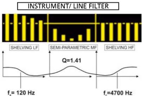
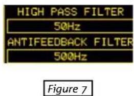
Specifically, you can select the following filters from the EQ submenu (figures 7, 8, 9):
| INPUT FILTER TYPE RANGE | ||
| MIC | HIGH PASS (HP) / ANTIFEEDBACK | HIGH PASS (HP): 50 ÷ 200 HzANTIFEEDBACK: 500 ÷ 12000 Hz |
| INSTRUMENT/LINE | LF: SHELVING / MF: SEMIPARAMETRIC / HF: SHELVING | LF/HF: -6 ÷ 4 dBMF: -6 ÷ 4 dB150 ÷ 4000 Hz (CENTER-FREQUENCY) |
bar
| Frequency | Value | | --------- | ----- | | f_a = 120 Hz | 1.41 | | f_c = 4700 Hz | 1.41 |Figure 8
text_image
HIGH PASS FILTER 50Hz ANTIFEEDBACK FILTER 500Hz Figure 7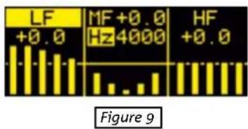
text_image
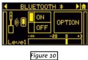
LF +0.0 MF+0.0 Hz4000 HF +0.0 Figure 9The stereo BLUETOOTH® channel sub page (figure 10) lets you set:
| NAME PARAMETER RANGE | ||
| ON/OFF | RECEIVER ON/OFF ON/OFF | |
| LEVEL | OUTPUT LEVEL (SENT TO THE INTERNAL MIXER) -∞ ÷ 3 dB | |
| OPTION | GAIN (INPUT GAIN) 0 ÷ 15 dB | |
| NAME (BLUETOOTH® SYSTEM NAME) | 16 ALPHANUMERIC CHARACTERS | |
| PASSWORD (BLUETOOTH® SYSTEM PASSWORD) 4 NUMERIC DIGITS | ||
| AUX | AUXILIARY SEND MIXER (NOT AVAILABLE IN DOUBLE COLUMN CONFIGURATION) | -∞ ÷ 3 dBSEE THE INPUT AND AUX MIXERS PARAGRAPH |
E. Select and confirm the MENU box to access the extended MENU (see the EXTENDED SETTINGS MENU chapter)
text_image
BLUETOOTH ON OPTION OFF Level -∞ -20 0 +3 Figure 10ES-1203 Cod. 420120253 REV. 1.0
RETURNING TO THE HOME PAGE WHILE BROWSING
To return to the HOME page from a sub page, select and confirm the symbol shown in figure 10. Alternatively, hold button [5] pressed for a few seconds (shortcut).
text_image
MAIN LEVEL Ch1 Ch2 Ch3 MENUFigure 10
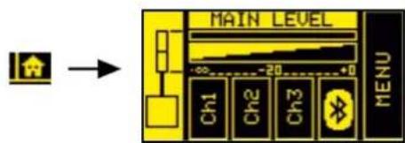
INPUT, OUTPUT AND AUX MIXERS
From the HOME page, hold button [5] pressed for a few seconds to access the input, output and AUX (auxiliary buses) mixer. The main pages are shown in figure 11.

In the DOUBLE COLUMN STEREO configuration, you cannot make any adjustments from the SLAVE system. You must set all the parameters on the MASTER system.
The mixer pages are:
- INPUTS mixer
- OUTPUTS mixer
- AUX mixer
To enter one of these 3 pages, select the corresponding word INPUTS, OUTPUTS or AUX, confirm and turn button [5].
The INPUTS page displays the CH1, CH2, CH3 and Bluetooth® levels.
The OUTPUTS page only displays the levels of the separate subwoofer sections and the system MAIN (total) section.
The AUX section has the levels of the channels that function as auxiliary buses in the mixer.
The latter section is especially useful when you want personalised monitoring assigned to the AUX output [6].
Consider the configuration shown in figure 12, in which output [6] of the ES1203 system is connected to a monitor.
You can, for example, use the INPUTS mixer to mix four sources connected to the system inputs, and make only two of them play through the connected monitor by adjusting the AUX levels independently.
flowchart
graph TD
    A["MAIN LEVEL MENU"] --> B["Input"]
    B --> C["INPUTS CH1 CH2 CH3"]
    C --> D["OUTPUTS Subwoofer MAIN"]
    D --> E["AUX"]
Figure 11
text_image
dBTech 6 AUX/MIX OUTPUT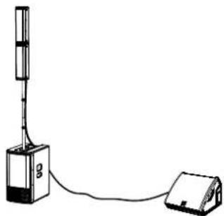
natural_image
Simple line drawing of a simple electrical device connected to a battery (no text or symbols)Figure 12
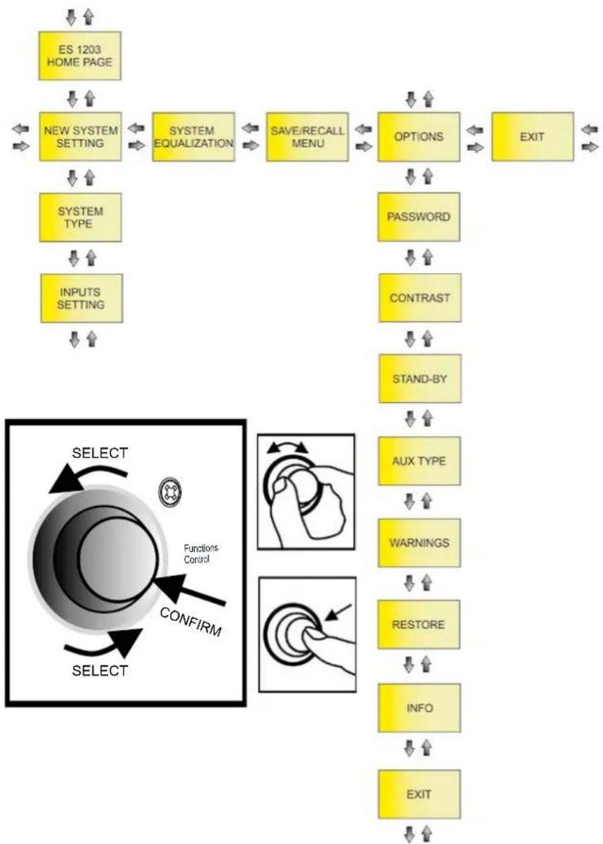
5. EXTENDED SETTINGS MENU
flowchart
graph TD
    A["ES 1203 HOME PAGE"] --> B["NEW SYSTEM SETTING"]
    B --> C["SYSTEM EQUALIZATION"]
    C --> D["SAVE/RECALL MENU"]
    D --> E["OPTIONS"]
    E --> F["EXIT"]
    G["SYSTEM TYPE"] --> H["INPUTS SETTING"]
    H --> I["PASSWORD"]
    I --> J["CONTRAST"]
    J --> K["STAND-BY"]
    K --> L["AUX TYPE"]
    L --> M["WARNINGS"]
    M --> N["RESTORE"]
    N --> O["INFO"]
    O --> P["EXIT"]
    Q["SELECT"] --> R["Functions Control"]
    R --> S["CONFIRM"]
    S --> T["SELECT"]
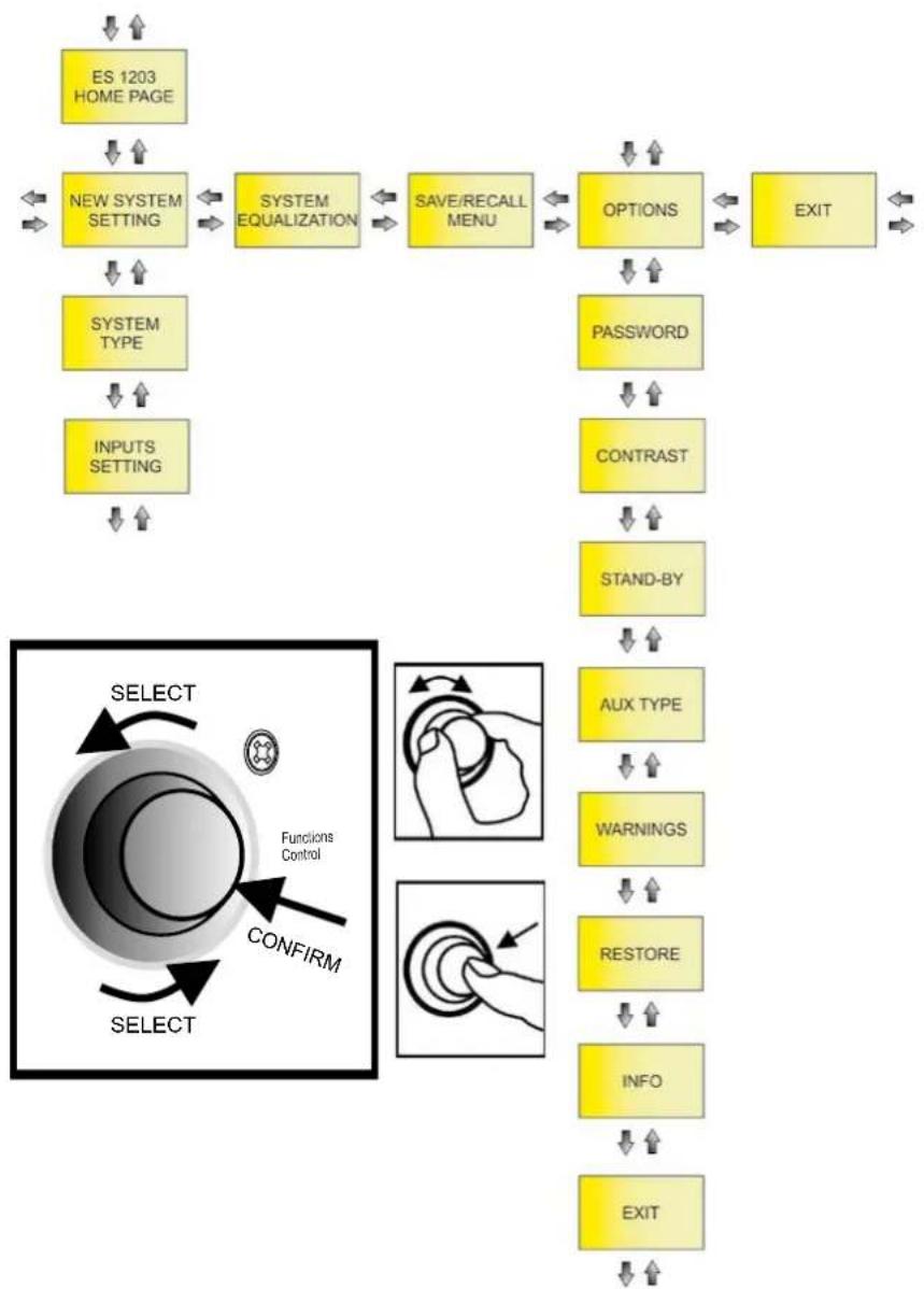
You can configure the ES1203 system in detail by accessing this MENU from the HOME page.
The main pages are:
- NEW SYSTEM SETTING
• SYSTEM EQUALIZATION - SAVE/RECALL MENU
- OPTIONS
As shown in the figure above, once you have accessed NEW SYSTEM SETTING and OPTIONS, you can access other settings sub pages (which differ according to the chosen main configuration). Use the Functions Control rotary button to confirm and select the pages as shown.
ES-1203 Cod. 420120253 REV. 1.0
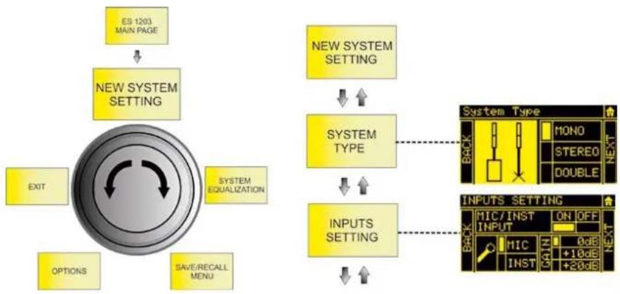
NEW SYSTEM SETTING
flowchart
graph TD
    A["ES 1203 MAIN PAGE"] --> B["NEW SYSTEM SETTING"]
    B --> C["EXIT"]
    B --> D["SYSTEM EQUALIZATION"]
    B --> E["OPTIONS"]
    B --> F["SAVE/RECALL MENU"]
    G["NEW SYSTEM SETTING"] --> H["SYSTEM TYPE"]
    H --> I["INPUTS SETTING"]
    I --> J["INPUTS SETTING"]
    K["System Type"] --> L["MONO"]
    K --> M["STEREO"]
    K --> N["DOUBLE"]
    O["BACK"] --> P["MONO"]
    O --> Q["STEREO"]
    O --> R["DOUBLE"]
    S["INPUTS SETTING"] --> T["MIC/INST ON OFF INPUT"]
    S --> U["MIC INST ON OFF INPUT"]
This sub page lets you quickly configure the system using the parameters listed in the table below:
| SYSTEM TYPE → | STEERING → | INPUTS SETTING | ||||
| MONO | MONO | UP | CH1, CH2, CH3 | ON/OFF | ||
| TYPE | MIC/INST (CH1) | |||||
| FAR | MIC/LINE/L+R (CH2, CH3) | |||||
| GAIN (0, +10, +20) dB | ||||||
| DOWN | BLUETOOTH | ON/OFF | ||||
| STEREO | STEREO | - | CH1, CH2, CH3 | ON/OFF | ||
| TYPE | MIC/INST (CH1) | |||||
| MIC/LINE/L+R (CH2, CH3) | ||||||
| GAIN (0, +10, +20) dB | ||||||
| BLUETOOTH | ON/OFF | |||||
| DOUBLE (MASTER) | DOUBLE | ML | UP | CH1, CH2, CH3 | ON/OFF | |
| TYPE | MIC/INST (CH1) | |||||
| FAR | MIC/LINE/L+R (CH2, CH3) | |||||
| MR | GAIN (0, +10, +20) dB | |||||
| DOWN | BLUETOOTH | ON/OFF | ||||
| DOUBLE (SLAVE) | SL | UP | - | |||
| FAR | ||||||
| SR | ||||||
| DOWN | ||||||
ES-1203 Cod. 420120253 REV. 1.0
SYSTEM EQUALIZATION
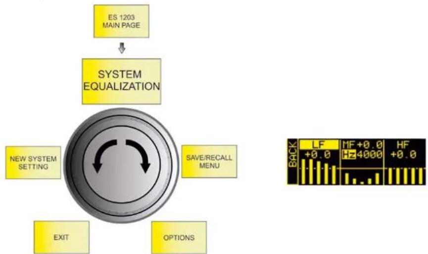
flowchart
graph TD
    A["ES 1203 MAIN PAGE"] --> B["SYSTEM EQUALIZATION"]
    B --> C["NEW SYSTEM SETTING"]
    B --> D["SAVE/RECALL MENU"]
    B --> E["EXIT"]
    B --> F["OPTIONS"]
    G["BACK"] --> H["LF +0.0 Hz 4000 HF +0.0"]
Sets the filtering that you want to apply to the system output sound:
| FILTER TYPE RANGE | |
| LF: SHELVING / MF: SEMIPARAMETRIC / HF: SHELVING | LF/HF: -6 - 4 dBMF: -6 - 4 dB150 - 4000 Hz (band centre) |
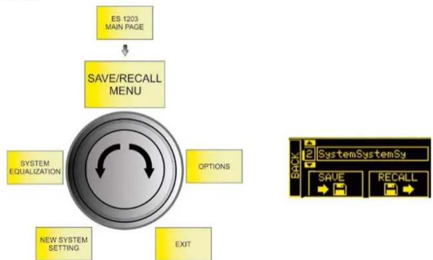
SAVE/RECALL MENU
flowchart
graph TD
    A["ES 1203 MAIN PAGE"] --> B["SAVE/RECALL MENU"]
    B --> C["SYSTEM EQUALIZATION"]
    B --> D["OPTIONS"]
    B --> E["NEW SYSTEM SETTING"]
    B --> F["EXIT"]
    G["System SystemSy"] --> H["BACK"]
    H --> I["SAVE"]
    H --> J["RECALL"]
- Highlight the SAVE image to save your settings
- Give a name to the configuration
- Highlight the RECALL image to recall a named configuration saved previously
ES-1203 Cod. 420120253 REV. 1.0
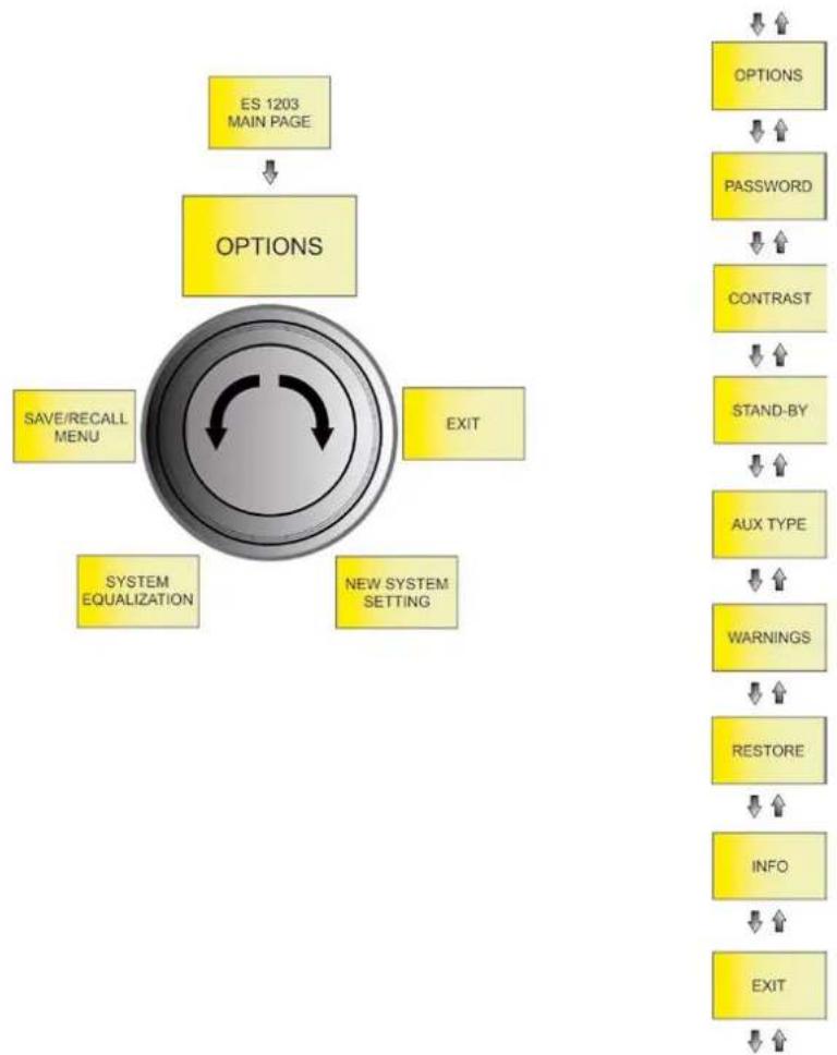
OPTIONS
flowchart
graph TD
    A["ES 1203 MAIN PAGE"] --> B["OPTIONS"]
    B --> C["SAVE/RECALL MENU"]
    B --> D["SYSTEM EQUALIZATION"]
    B --> E["EXIT"]
    B --> F["NEW SYSTEM SETTING"]
    G["OPTIONS"] --> H["PASSWORD"]
    H --> I["CONTRAST"]
    I --> J["STAND-BY"]
    J --> K["AUX TYPE"]
    K --> L["WARNINGS"]
    L --> M["RESTORE"]
    M --> N["INFO"]
    N --> O["EXIT"]
PASSWORD
-
Enables/disables the use of a password to protect the systems settings. There are three protection levels:
-
LEVEL 1 - Lets you operate at the general MAIN LEVEL and load presets but not save them
- LEVEL 2 - Lets you operate only at the general MAIN LEVEL
-
LEVEL 3 - Does not let you change any system settings
-
Enter a password.
You can only use a 6-digit numeric password.
If you lose it, use the SUPERUSER code: Q2R5D9.
ES-1203 Cod. 420120253 REV. 1.0
CONTRAST
Adjusts the OLED screen contrast (from 0% to 100% in steps of 5%).
STAND-BY
- Enables/disables OLED screen auto power-off (the system remains on)
- Choose the time after which the screen turns off (from 10 seconds to 10 minutes in steps of 10 seconds)
AUX TYPE
As in a mixer, the AUX sends may be affected by fader adjustments or not:
- PRE - the AUX send is taken before the system mixer settings, which is particularly suited to using the ES1203 system output for sending a signal to a separate monitor. In this case, the output signal is independent of the internal mixer settings.
- POST - the AUX send is taken after all the system adjustments, so the ES1203 system outputs a signal that is affected by all the internal mixer settings.
WARNINGS
This page displays any active system warnings.
RESTORE
Lets you return the system to its factory settings.
INFO
Displays the system firmware revision.
EXIT
Exits from the OPTIONS page.
ES-1203 Cod. 420120253 REV. 1.0
6. ACCESSORIES
The following optional accessories are available to complete the range:
• DO-ES212 trolley - helps you move the disassembled system
- DP-ES1203 design pole - gives you a more uniform appearance in the MONO / DOUBLE COLUMN STEREO configuration
- WB-44 wall bracket - lets you wall-mount a single top or a double top (for fixed installation of any system configuration type)
Check for new compatible accessories at www.dbtechnologies.com.
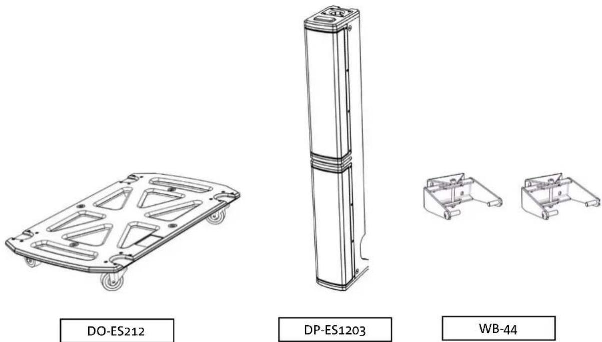
Consult the accompanying instructions for further details on using accessories.
ES-1203 Cod. 420120253 REV. 1.0
7. TROUBLESHOOTING
The system will not turn on:
- Check that the system is connected to a working power supply.
- Check that the power cable with VDE connector is plugged in properly and that the power switch is in the ON position.
The diffuser turns on but does not emit any sound:
- Check that the audio signal input is connected correctly.
- Check that the cables used are not damaged.
- Check the connections between the tops and the subwoofer.
- Check that the mixer or audio source is on and clearly shows an output signal.
- Check that the input level, input type and output level are suitable.
The sound emitted by the diffuser is insufficient or distorted:
- Check that the cables used are not damaged. If they are, replace them (a damaged cable may cause signal loss or alteration).
- Check that the input level, input type and output level are suitable.
The OLED screen appears to be off:
- Check that the STAND-BY option in the OPTION menu is not enabled
ES-1203 Cod. 420120253 REV. 1.0
8. UPDATING THE FIRMWARE
It is very important to keep the product firmware updated to ensure full functionality. Periodically check the "DOWNLOADS" section of the http://www.dbtechnologies.com website.

text_image
hnologies 8 Service Data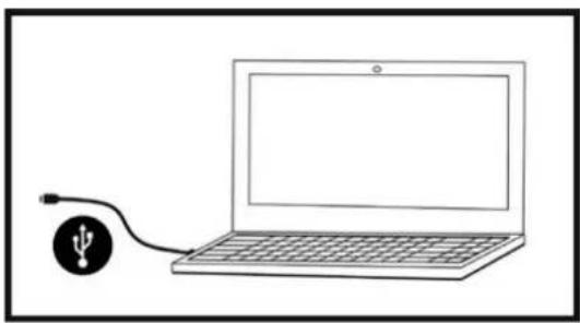
natural_image
Simple line drawing of a laptop connected to a USB cable (no text or symbols)- Download and install the USB BURNER MANAGER onto your computer from the "SOFTWARE & CONTROLLER" section.
- Download the .zip file for your product from the "DOWNLOADS" section.
- Connect the product to the PC using a USB cable (not supplied) with the correct connector type (see this detail in the AMPLIFIER AND CONTROL SECTION FEATURES chapter).
- Select "Open File" at the top right of the USB BURNER MANAGER screen.
- Select the previously downloaded firmware file.
- Follow the instructions shown on the screen.
- Click "UPDATE".
9. TECHNICAL SPECIFICATIONS
GENERAL
Type: Tri-amplified system (Mono/Stereo)
ACOUSTIC DATA
| Frequency response [-10dB]: | 35 - 20000 Hz |
| Frequency response [-6dB]: | 41 - 18000 Hz |
| Max SPL (1 m): | 132 dB |
| MF-HF mid woofer: | 4 x 4" (each TOP) |
| MF-HF voice coil: | 25 mm |
| LF woofer: | 2 x 12" (subwoofer) |
| LF voice coil: | 64 mm |
| Crossover frequency: | 160 Hz (24 dB/oct) |
| Directivity: | Asymmetrical vertical |
| Coverage (HxV): | 97° x 60° (single top) |
AMPLIFIER
| Type: | DIGIPRO G4 |
| Amplification class | Class D |
| Power connection | 1 x VDE |
| RMS amplification power: | 1200 W |
ES-1203 Cod. 420120253 REV. 1.0
| Internal controller: | 28/56 bit DSP |
| A/D D/A converter: | 24 bit/48 kHz |
| Limiter: | Peak, RMS, Thermal |
USER INTERFACE
| Controls: | OLED display, push/rotary encoder |
INPUTS AND OUTPUTS
| Inputs: | 1 x Combo (XLR/Jack) MIC/INSTRUMENT, 2 x Combo (XLR/Jack) MIC/LINE |
| Built-in input: | 1x Bluetooth® |
| Output: | 1 x XLR output |
POWER SUPPLY SPECIFICATIONS (CONSUMPTION / INSTALLATION)
| Consumption at 1/8 of the power under normal operating conditions (*): | 1.1 A (220 - 240 V~) - 2.2 A (100 - 120 V~) |
| Consumption at 1/3 of the power under maximum operating conditions (**): | 2.1 A (220 - 240 V~) - 4.5 A (100 - 120 V~) |
| Consumption with speaker on and no signal (idle): | 26 W |
| Inrush current: | 9.15 A (230 V~) |
* NOTE FOR THE INSTALLER: Values refer to 1/8 of the power under normal operating conditions (musical program with rare or no clipping). For any configuration type, we recommend considering them to be the minimum values for dimensioning.
** NOTE FOR THE INSTALLER: Values refer to 1/3 of the power under heavy operating conditions (musical program with frequent clipping and limiting). We recommend dimensioning according to these values for installations and professional tours.
ES-1203 Cod. 420120253 REV. 1.0
DIMENSIONS
| Material: | Wood (plywood) |
| Grille: | Metal, 1.5 mm thick, CNC machined |
| Handles: | 3 (2 at the sides, 1 on top) |
| Pole mounting: | Yes, M20 |
| Width: | 360 mm (subwoofer) / 110 mm (top) |
| Height: | 680 mm (subwoofer) / 460 mm (top) |
| Depth: | 545 mm (subwoofer) / 160 mm (top) |
| Weight: | 29.3 kg (subwoofer) / 3.3 kg (top) |
Product features, specifications and appearance are subject to change without prior notice. dBTechnologies reserves the right to make changes or improvements in design or manufacturing without any obligation to change or improve previously manufactured products.

text_image
AEBA.E.B. Industriale Srl
Via Brodolini, 8
text_image
Diagram illustrating the assembly of a server rack with labeled components and tool path, showing internal components and assembly steps.natural_image
Diagram of a computer tower case showing internal circuit board and ventilation slots (no text or labels)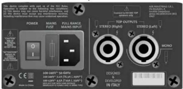
text_image
This device varies with part of the ICC-400. Operation is subject to the following two conditions: (1) This device may use one case harmful interference, and (2) This device may use another sound artifact or sound artifact, including interference that may issue undesired operation. POWER MAINS FUSE FULL RANGE MAINS INPUT *CAUTION *ONION *STATION *ONION *STATION *STATION *STATION *STATION *STATION *STATION *STATION *STATION *STATION *STATION *STATION *STATION *STATION *STATION *STATION *STATION *STATION *STATION *STATION *STATION *STATION *STATION *STATION *STATION *STATION *STUTION *STUTION *STUTION *STUTION *STUTION *STUTION *STUTION *STUTION *STUTION *STUTION *STUTION *STUTION *STUTION *STUTION *STUTION *STUTION *STUTION *STUTION *STUTION *STUTION *STUTION *STUTION *STUTION *STUTION *STUTION *STUTRONE TOP OUTPUTS STEREO (Right) STEREO (Left) MONO DESIGNED DEVELOPED IN ITALYBEREICH FÜR INPUT, OUTPUT UND CONTROL

text_image
Entertainment 1203 gm 7 Peak 4 5 Functions Control MIC / INSTRUMENT INPUT CH 1 LINE / MIC INPUT CH 2 LINE / MIC INPUT dB Technologies 6 8 Service Data Left Right AUX/MIX OUTPUT1. Balanced Input MIC/INSTRUMENT
2. Balanced Input LINE/MIC (CH.1)
3. Balanced Input LINE/MIC (CH.2)
5. Functions control (Push-rotary encoder)
text_image
This device complies with part 15 of the FCC Rules. Operation is subject to the following two conditions: (1) This device may not cause harmful interference, and (2) this device must accept any interference received, including interference that may cause undesired operation. POWER MAINS FUSE FULL RANGE MAINS INPUT "CAUTION" RISK OF ELECTRICAL BLOCK DO NOT OPEN "ATTENTION" BISQUE DE CHOCHE ELECTRICUE NE PAS OUVERIK Made in China 12 13 11 10 DESIC & DEVELOPED IN ITALY 9 AEB INDUSTRIALE S.R.L. Via Brodiolini, 8 Località Crespeliano 400S3 VALSAMOGGIA (BO) ITALY POWER MAINS FUSE FULL RANGE MAINS INPUT TOP OUTPUTS STEREO (Right) STEREO (Left) MONO *9. Left TOP OUTPUT (MONO)
natural_image
Illustration of a setup with two tall-mounted devices and a central server unit connected to a tripod (no text or symbols visible)natural_image
Technical line drawing of a multi-tiered device labeled 'MONO' (no other text or symbols)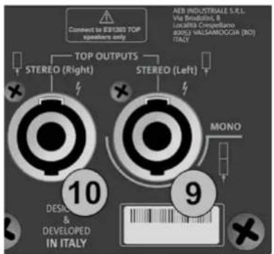
text_image
Connect to EBIT200 TOP speakers only TOP OUTPUTS STEREO (Right) STEREO (Left) AER INDUSTRIALE S.R.L. Via Broodini, B Lucatista Crespellano BOSI MALSAMOGGIA (NO) ITALY 10 DESIC & DEVELOPED IN ITALY 9 MONO
natural_image
Two identical electrical enclosure units with black cables inserted, no text or symbols visibleSTEREO
text_image
Connect to EBIT280 TOP speakers only TOP OUTPUTS STEREO (Right) STEREO (Left) AEB INDUSTRIALE S.R.L. Via Broodini, B Localisi Despiellano 30/51) VALSAMOGGIA (BO) ITALY 10 DESCI & DEVELOPED IN ITALY 9 MONO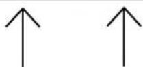
ES-1203 Cod. 420120253 REV. 1.0
text_image
(1) This device may not cause minimum interference, and (2) this device must accept any interference received, including interference that may cause undesired operation. POWER MAINS FUSE FULL RANGE FAINS INPUT "CAUTION" RISK OF ELECTRICAL SHOCK DO NOT OPEN "ATTENTION" RISQUE DE CREAST ELECTROUPE NE PAS OUVRIN 12 13 11 100-250V~ 60Hz 220-240V~ 2.1A (T6.3A L 250V~) 100-120V~ 4.5A (T10A L 250V~) (DRPLACE FUSE WITH SAME RATINGS) (REEMPLACER LE PUSIBLE AVEC LE MÊME TYPE) Made in China STROMVERSORGUNG (VDE-STECKER)
text_image
entertainment 1203 System Peak es 1203 v 01 00 01 4 Functions Control MIC / INSTRUMENT INPUT CH 1 LINE / MIC INPUT CH 2 LINE / MIC INPUT dBTechnologies Service Data Left Right AUX/MIX OUTPUT4. HOMEPAGE, QUICK CONTROLS, MIXER
text_image
MAIN LEVEL CH1 CH2 CH3 ME 4 5 Functions Controltext_image
LF +0.0 MF +0.0 Hz 4000 HF +0.0Abbildung 9
- INPUTS mixer
- OUTPUTS mixer
- AUX mixer
natural_image
Simple line drawing of a simple electrical device connected to a battery (no text or symbols)Abbildung 12
text_image
hnologies 8 Service Data
natural_image
Simple line drawing of a laptop connected to a USB symbol (no text or labels)CONNEXION DES COUVERCLES AU SUBWOOFER 98
CONNEXION DES ENTRÉES.... 99
CONNEXION DE LA SORTIE DU SYSTÈME 100
CONNEXION DE L'ALIMENTATION EN ÉNERGIE ÉLECTRIQUE 101
4. PAGE D'ACCUEIL, CONTRÔLES RAPIDES, MÉLANGEURS.... 102
5. MENU ÉTENDU DES PARAMÉTRAGES 106
6. ACCESSOIRES.... 111
7. DÉPANNAGE 112
8. MISE À JOUR DU MICROLOGICIEL 113
9. SPÉCIFICATIONS TECHNIQUES 114
GÉNÉRALES 114
DONNÉES ACOUSTIQUES 114
AMPLIFICATEUR.... 114
TEMPÉRATURE D'UTILISATION.... 115
PROCESSEUR.... 115
INTERFACE UTILISATEUR 115
ENTRÉES ET SORTIES.... 115
1. GÉNÉRALITÉS
BIENVENUE !
text_image
Diagram illustrating the assembly of a server unit with labeled components and a mechanical tool mechanism.flowchart
graph TD
    A["Raw Materials"] --> B["Coated Bags"]
    B --> C["Coated Pressers"]
    C --> D["Packaging Unit"]
    D --> E["Internal Components"]
    E --> F["Assembly Paper Cases"]
    F --> G["Final Packaging Box"]

    subgraph Component 1
        H["Coated Bags & Paper"] --> I["Coated Pressers"]
        J["Coated Paper Cases"] --> K["Coated Pressers"]
    end

    subgraph Component 2
        L["Coated Bags & Paper"] --> M["Coated Pressers"]
        N["Coated Paper Cases"] --> O["Coated Pressers"]
    end

    subgraph Component 3
        P["Coated Bags & Paper"] --> Q["Coated Pressers"]
        R["Coated Paper Cases"] --> S["Coated Pressers"]
    end

    subgraph Component 4
        T["Coated Bags & Paper"] --> U["Coated Pressers"]
        V["Coated Paper Cases"] --> W["Coated Pressers"]
    end

    subgraph Component 5
        X["Coated Bags & Paper"] --> Y["Coated Pressers"]
        Z["Coated Paper Cases"] --> AA["Coated Pressers"]
    end

    subgraph Component 6
        AB["Coated Bags & Paper"] --> AC["Coated Pressers"]
        AD["Coated Paper Cases"] --> AE["Coated Pressers"]
    end

    subgraph Component 7
        AF["Coated Bags & Paper"] --> AG["Coated Pressers"]
        AH["Coated Paper Cases"] --> AI["Coated Pressers"]
    end

    subgraph Component 8
        AJ["Coated Bags & Paper"] --> AK["Coated Pressers"]
        AL["Coated Paper Cases"] --> AM["Coated Pressers"]
    end

    subgraph Component 9
        AN["Coated Bags & Paper"] --> AO["Coated Pressers"]
        AP["Coated Paper Cases"] --> AQ["Coated Pressers"]
    end

    subgraph Component 10
        AR["Coated Bags & Paper"] --> AS["Coated Pressers"]
        AT["Coated Paper Cases"] --> AU["Coated Pressers"]
    end
natural_image
Diagram of a device rear panel with internal circuit board and ports, showing directional arrows (no text or symbols)AMPLIFICATEUR

text_image
This device sample with part 31 of the FCC Rules. Operation to export in the following two conditions: (1) This device may not close harmful interconnects, and in particular, double-tensile input and output. Including interference that may cause undistorted operation. POWER MAINS FUSE FULL RANGE MAINS INPUT "CAUTION" FOR IN LXXX FOR IN LXXX FOR IN LXXX FOR IN LXXX MODE IN CHINA 180V-240V~ 200V-340V~ 300V-440V~ 400V-540V~ 500V-640V~ 600V-740V~ 700V-840V~ 800V-940V~ 900V-1040V~ MINIMUM OUTPUTS STEREO (Right) STEREO (Left) MONO DESIGNED A DEVELOPED IN ITALYSECTION D'ALIMENTATION ET DE CONNEXION DES << TOP >>
SECTION D'ENTRÉE, DE SORTIE ET DE CONTRÔLE
text_image
entertainment 1203 Peak 7 4 5 Functions Control MIC / INSTRUMENT INPUT CH 1 LINE / MIC INPUT CH 2 LINE / MIC INPUT dB Technologies Service Data 1 2 3 6 8 Left Right AUX/MIX OUTPUT1. Balanced Input MIC/INSTRUMENT
2. Balanced Input LINE/MIC (CH.1)
3. Balanced Input LINE/MIC (CH.2)
5. Functions control (Push-rotary encoder)
text_image
This device complies with part $5 of the FCC Rules. Operation is subject to the following two conditions: (1) This device may not cause harmful interference, and (2) this device must accept any interference received, including interference that may cause undesired operation. POWER MAINS FUSE FULL RANGE MAINS INPUT "CAUTION" RISK OF ELECTRICAL BROCK DO NOT OPEN "ATTENTION" RISQUE DE CHICK ELECTROUZ NE PAS OUVIR Made in China 12 13 11 10 10 9 TOP OUTPUTS STEREO (Right) STEREO (Left) MONO DESICUM & DEVELOPED IN ITALY9. Left TOP OUTPUT (MONO)
natural_image
Diagram of a vertical cylindrical device with a base and height measurement arrow, no text or symbols presentMAX 70 cm *
B - STÉRÉO
natural_image
Line drawing of a setup with two tall-mounted devices and a central server unit connected to a tripod (no text or symbols)C - DOUBLE COLONNE STÉRÉO
CONNEXION DES COUVERCLES AU SUBWOOFER
CONFIGURATION MONO
natural_image
Technical line drawing of a multi-tiered device labeled 'MONO' (no other text or symbols)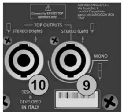
text_image
Connect to BYRBO TOP speakers only TOP OUTPUTS STEREO (Right) STEREO (Left) AER INDUSTRIALE S.R.L. Via Broodini, 8 Locatella Crispellano (ISO) VALSAMOGGIA (RO) ITALY 10 DESIC & DEVELOPED IN ITALY 9 MONO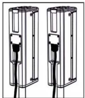
natural_image
Two identical electrical enclosure units with black cables inserted, no text or symbols visibleSTEREO
text_image
Connect to EBITED TOP speakers only TOP OUTPUTS STEREO (Right) STEREO (Left) MONO 10 DESIGN & DEVELOPED IN ITALY 9 AEB INDUSTRIATE S.R.L. Via Brocolini, B Ivarialia Compellano 800,3 VILLAMIOOGIA (BO) ITALY
ES-1203 Cod. 420120253 REV. 1.0
CONNEXION DES ENTRÉES
PREMIER EXAMPLE
text_image
(1) This device may not cause harmful interference, and (2) this device must accept any interference received, including interference that may cause undesired operation. POWER MAINS FUSE FULL RANGE FAILS FUSE MAINS INPUT "CAUTION" RISK OF ELECTRICAL SHORT DO NOT OPEN "ATTENTION" RISQUE DE CHOCHE ELECTRIOUE IN PAS OUVERI! 12 13 11 CE 100-240V~ 60Hz 220-240V~ 2.1A (T6.3A L 250V~) 100-120V~ 4.5A (T10A L 250V~) (REPLACE FUSE WITH SAME RATINGS) (REPLACER LE FUSIBLE AVECLE RIME TYPE) Made in China ↑ALIMENTATION (CONNECTEUR VDE)
text_image
entertainment 1203 System Peak es 1203 v.01.00.01 4 Functions Control MIC / INSTRUMENT INPUT CH 1 LINE / MIC INPUT CH 2 LINE / MIC INPUT dBTechnologies Service Data Left Right AUX/MIX OUTPUT4. PAGE D'ACCUEIL, CONTRÔLES RAPIDES, MÉLANGEURS
text_image
MAIN LEVEL 4 CH1 CH2 CH3 ME 5 Functions Controlnatural_image
Two-step diagram showing hand press application on a circular button, with arrows indicating rotation direction (no text or symbols)PAGE D'ACCUEIL
text_image
A B C MAIN LEVEL MENU E Ch1 Ch2 + Ch3 D D D Figure 1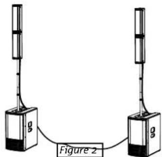
text_image
g Figure 2text_image
LF +0.0 MF +0.0 Hz 4000 HF +0.0Figure 9
- INPUTS mixer
- OUTPUTS mixer
- AUX mixer
natural_image
Simple line drawing of a simple electrical device with a vertical pole and connected to a base (no text or symbols)Figure 12
ES-1203 Cod. 420120253 REV. 1.0
5. MENU ÉTENDU DES PARAMÉTRAGES
flowchart
graph TD
    A["ES 1203 HOME PAGE"] --> B["NEW SYSTEM SETTING"]
    B --> C["SYSTEM EQUALIZATION"]
    C --> D["SAVE/RECALL MENU"]
    D --> E["OPTIONS"]
    E --> F["EXIT"]
    G["SYSTEM TYPE"] --> H["INPUTS SETTING"]
    H --> I["PASSWORD"]
    I --> J["CONTRAST"]
    J --> K["STAND-BY"]
    K --> L["AUX TYPE"]
    L --> M["WARNINGS"]
    M --> N["RESTORE"]
    N --> O["INFO"]
    O --> P["EXIT"]
    Q["SELECT"] --> R["Functions Control"]
    R --> S["CONFIRM"]
    S --> T["SELECT"]
text_image
hnologies 8 Service Data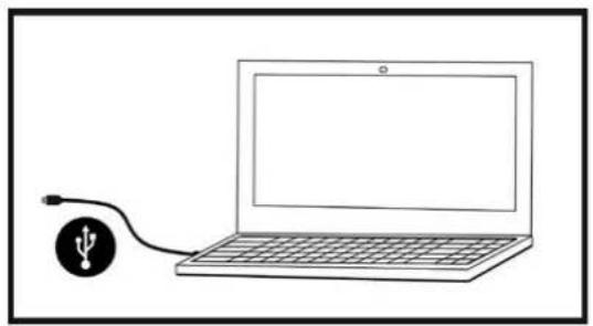
natural_image
Simple line drawing of a laptop connected to a USB symbol (no text or labels)C - DOBLE COLUMN A ESTÉREO 125
text_image
60° 97° DIGITAL STEERINGES-1203 Cód. 420120253 REV. 1.0
text_image
Diagram illustrating a mechanical assembly process with labeled components and directional arrows indicating motion or assembly steps.flowchart
graph TD
    A["Device Packaging"] --> B["Assembly"]
    B --> C["Assembly with Paper Towels"]
    C --> D["Assembly with Paper Towels"]
    D --> E["Assembly with Paper Towels"]
    E --> F["Assembly with Paper Towels"]
    F --> G["Final Product Delivery"]

    subgraph Initial Assembly
        H["Two 3D Systems with Cable"] --> I["Add Cable to Device"]
        J["Add Cable to Device"] --> K["Add Cable to Device"]
    end

    subgraph Equipment Setup
        L["Assembly with Paper Towels"] --> M["Assembly with Paper Towels"]
        N["Assembly with Paper Towels"] --> O["Assembly with Paper Towels"]
        P["Assembly with Paper Towels"] --> Q["Assembly with Paper Towels"]
        R["Assembly with Paper Towels"] --> S["Assembly with Paper Towels"]
        T["Assembly with Paper Towels"] --> U["Assembly with Paper Towels"]
        V["Assembly with Paper Towels"] --> W["Assembly with Paper Towels"]
        X["Assembly with Paper Towels"] --> Y["Assembly with Paper Towels"]
        Z["Assembly with Paper Towels"] --> AA["Assembly with Paper Towels"]
    end

    subgraph Final Assembly
        AB["Assembly with Paper Towels"] --> AC["Assembly with Paper Towels"]
        AD["Assembly with Paper Towels"] --> AE["Assembly with Paper Towels"]
        AF["Assembly with Paper Towels"] --> AG["Assembly with Paper Towels"]
        AH["Assembly with Paper Towels"] --> AI["Assembly with Paper Towels"]
        AJ["Assembly with Paper Towels"] --> AK["Assembly with Paper Towels"]
        AL["Assembly with Paper Towels"] --> AM["Assembly with Paper Towels"]
        AN["Assembly with Paper Towels"] --> AO["Assembly with Paper Towels"]
        AP["Assembly with Paper Towels"] --> AQ["Assembly with Paper Towels"]
        AR["Assembly with Paper Towels"] --> AS["Assembly with Paper Towels"]
        AT["Assembly with Paper Towels"] --> AU["Assembly with Paper Towels"]
        AV["Assembly with Paper Towels"] --> AW["Assembly with Paper Towels"]
        AX["Assembly with Paper Towels"] --> AY["Assembly with Paper Towels"]
natural_image
Diagram of a computer monitor case with internal circuit board and ventilation slots (no text or labels)AMPLIFICADOR
text_image
This device contains with part of the FCC Rules Operation is subject to the following two conditions: SO THIS device may not close harmful interference, and this device must be heard and therefore read. Including Interference that may cause ordered operation. POWER MAINS FUSE FULL RANGE MAINS INPUT "CAUTION" BEET GELIC IN FOR IN ATTENTION RANGE OF DESCRIPTION WEED OUTDOOR 100-240V~ 50-60Hz 200-340V~ 2.1A (TR/3A L 200V~) 100-120V~ 4.5A (TR/3A L 200V~) DESIGNED DEVELOPED IN ITALY STEREO (Right) STEREO (Left) MONO ENGLISHING OR IL- FOR RESOLVED, COORDING CYPICALS, AND VALUATION (BOS) ONLY1. Balanced Input MIC/INSTRUMENT
2. Balanced Input LINE/MIC (CH.1)
3. Balanced Input LINE/MIC (CH.2)
5. Functions control (Push-rotary encoder)
text_image
This device complies with part 15 of the FCC Rules. Operation is subject to the following two conditions: (1) This device may not cause harmful interference, and (2) this device must accept any interference received, including interference that may cause undesired operation. POWER MAINS FUSE FULL RANGE MAINS INPUT "CAUTION" RMS OF ELECTRICAL BROCK DO NOT OPEN "ATTENTION" BISQUE DE CROCK ELECTRIOUE NE PAS OÜVIER 12 13 11 10 9 AEB INDUSTRIALE S.R.L. Via Brodalini, 8 Località Crespettano 40053 VALSAMOGGIA (BO) ITALY POWER MAINS FUSE FULL RANGE MAINS INPUT STEREO (Right) STEREO (Left) MONO DESICUM & DEVELOPED IN ITALY Made in China9. Left TOP OUTPUT (MONO)
natural_image
Illustration of a setup with two tall speakers and a central computer case connected to a tripod, no text or symbols present.C - DOBLE COLUMNNA ESTÉREO
natural_image
Technical line drawing of a multi-tiered device labeled 'MONO' (no other text or symbols)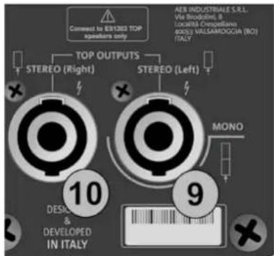
text_image
Connect to 63/1203 TOP speakers only TOP OUTPUTS STEREO (Right) STEREO (Left) AER INDUSTRIALE S.R.L. Via Strodoline, B Localita Crespellano NOSO VALLSAMDOGGA (NO) ITALY 10 DESIC & DEVELOPED IN ITALY 9 MONO

natural_image
Two identical mechanical components with black connectors and a central connector, shown side by side (no text or symbols)STEREO
text_image
Comment to 891205 TOP speakers only TOP OUTPUTS STEREO (Right) STEREO (Left) AEB INDUSTRIALE S.R.L. Via Broodini, B LocalBA Crempellano 600G VALIAMOGGIA (NO) (ITA) 10 DESIGN & DEVELOPED IN ITALY 9 MONO
ES-1203 Cód. 420120253 REV. 1.0
text_image
(1) this device may not cause harmful interference, and (2) this device must accept any interference received, including interference that may cause undesired operation. POWER MAINS FUSE FULL RANGE FAINS INPUT "CAUTION" RISK OF ELECTRICAL STOCK DO NOT OPEN "ATTENTION" RISQUE DE CHICK ELECTRISQUE NE PAS OUTVIRI 12 13 11 100-250V~ 60Hz 220-240V~ 2.1A (T6.3A L 250V~) 100-120V~ 4.5A (T10A L 250V~) (REPLACE FUSE WITH SAME RATINGS) (REEMPLACER LE FUSIBLE AVEC LE MEME TYPE) Made in Chinanatural_image
Two-step diagram showing hand press application on a circular button, with arrows indicating rotation (no text or symbols)PÁGINA DE INICIO
text_image
MAIN LEVEL Ch1 Ch2 + Ch3 Ch1 Ch2 Ch3 Ch3 Ch3 Ch3 Ch3 Ch3 Ch3 Ch3 Ch3 Ch3 Ch3 Ch3 Ch3 Ch3 Ch3 Ch3 Ch3 Ch3 Ch3 Ch3 Ch3 Ch3 Ch3 Ch3 Ch3 Ch3 Ch3 Ch3 Ch3 Ch3 Ch3 Ch3 Ch3 Ch3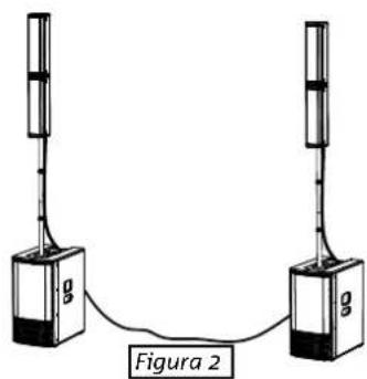
text_image
g g Figura 2text_image
LF +0.0 MF +0.0 Hz 4000 HF +0.0Figura 9
- INPUTS mixer
- OUTPUTS mixer
- AUX mixer
natural_image
Simple line drawing of a simple electrical device with a vertical tube connected to a base and a small box (no text or symbols)Figura 12
5. MENÚ AMPLIADO DE AJUSTES
flowchart
graph TD
    A["ES 1203 HOME PAGE"] --> B["NEW SYSTEM SETTING"]
    B --> C["SYSTEM EQUALIZATION"]
    C --> D["SAVE/RECALL MENU"]
    D --> E["OPTIONS"]
    E --> F["EXIT"]
    G["SYSTEM TYPE"] --> H["INPUTS SETTING"]
    H --> I["PASSWORD"]
    I --> J["CONTRAST"]
    J --> K["STAND-BY"]
    K --> L["AUX TYPE"]
    L --> M["WARNINGS"]
    M --> N["RESTORE"]
    N --> O["INFO"]
    O --> P["EXIT"]
    Q["SELECT"] --> R["Functions Control"]
    R --> S["CONFIRM"]
    S --> T["SELECT"]
text_image
hnologies 8 Service Data