
ZIABH1500D - Hammer Zipper - Free user manual and instructions
Find the device manual for free ZIABH1500D Zipper in PDF.

| Product Type | Breaker Hammer |
| Brand | Zipper |
| Model | ZIABH1500D |
| Motor Power | 1500 W |
| Impact Frequency | 1900 blows/min |
| Impact Energy | 45 J |
| Supply Voltage | 230 V / 50 Hz |
| Weight | 14 kg |
| Protection Class | II |
| Protection Rating | IP 20 |
| Sound Pressure Level (LpA) | 93 dB(A) |
| Sound Power Level (LwA) | 105 dB(A) |
| Vibration (ah, Cheq) | 20.706 m/s² |
| Tool Dimensions | 30 x 410 mm (hexagonal) |
| Recommended Oil | 15W40 |
| Oil Tank Capacity | Approximately 20 days of operation (3-4 h/day) |
| Delivery Contents | Flat chisel, point chisel, carbon brushes, filling oil, Allen key, fork wrench |
| Intended Use | Chiseling in concrete, brick, and stone |
| Ambient Operating Temperature | +5 °C to +40 °C |
| Max Ambient Humidity | 70 % |
| Carbon Brush Maintenance | Replacement recommended every 100 operating hours |
Frequently Asked Questions - ZIABH1500D Zipper
User questions about ZIABH1500D Zipper
0 question about this device. Answer the ones you know or ask your own.
Ask a new question about this device
Download the instructions for your Hammer in PDF format for free! Find your manual ZIABH1500D - Zipper and take your electronic device back in hand. On this page are published all the documents necessary for the use of your device. ZIABH1500D by Zipper.
USER MANUAL ZIABH1500D Zipper
ATTENTION: Check Oil (15W40)!
CE
[Non-Text]

1 INHALT / INDEX
1 INHALT / INDEX 2
11.1 Intended Use....20
11.2 Remaining risk factors.... 22
12 OPERATION
22
12.1 Operation instructions.... 22
12.2 Operation 23
12.2.1 Insert chisel 23
12.2.2 Switch on....23
12.2.3 Switch off....24
12.2.4 Filling with oil 24
13 MAINTENANCE
25
13.1 Maintenance plan 25
13.2 Changing the carbon brushes 25
13.3 Cleaning 26
13.4 Disposal....26
14 TROUBLE SHOOTING
26
15 PREFACE (FR)
27
16 TECHNIQUE
28
EN CE-CONFORM: This product complies with EC-directives
EN READ THE MANUAL! Read the user and maintenance manual carefully and get familiar with the controls in order to use the machine correctly and to avoid injuries and machine defects.
EN ATTENTION! Ignoring the safety signs and warnings applied on the machine as well as ignoring the security and operating instructions can cause serious injuries and even lead to death.
EN Protective clothing!
FR Vêtement de protection!
EN Stop and pull out the power plug before any break and engine maintenance!
EN Operation with jewelry forbidden!
EN Operation with tie forbidden!
EN Operation with long hair forbidden!
EN Warning of rotating parts!
EN Protect from moisture!
EN Protection class II!
FR Protection classe II!
SL Zaščitni razred II!
natural_image
Close-up of a metallic mechanical component with hexagonal bolt and threaded shaft (no visible text or symbols)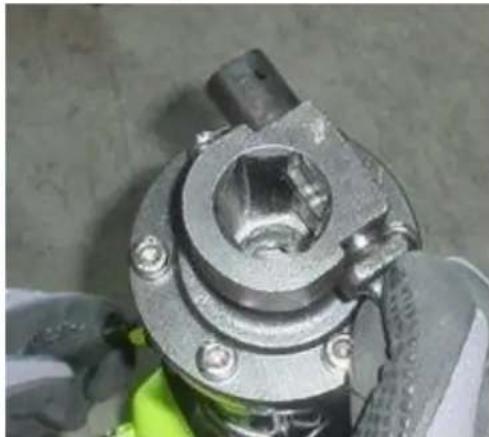
natural_image
Close-up of a mechanical component with bolts and a central hub, partially covered by gloved hands (no visible text or symbols)natural_image
Close-up of a metallic mechanical component with bolts and a cylindrical shaft (no visible text or symbols)6.2.2 Einschalten
natural_image
Close-up of a hand holding a green spray gun and black textured object against a concrete wall (no text or symbols visible)
natural_image
Close-up of a hand holding a green and black plastic object against a textured wall (no text or symbols visible)6.2.3 Ausschalten
natural_image
Close-up of a mechanical device with a metallic bolt and green base, showing no visible text or symbols.
natural_image
Close-up of a mechanical component with a green base and metal housing, showing a yellow label and a hexagonal bolt (no readable text or symbols)natural_image
Close-up of a green ER water heater with a screwdriver inserted, no visible text or symbols
natural_image
Close-up of a green industrial machine component with a metallic tool inserted, no visible text or symbols
natural_image
Close-up of a green industrial machine component with a metal screw inserted, no visible text or symbolsThis manual contains important information and advice for the correct and safe use and maintenance of the demolition hammer ZI-ABH1500D / ZI-ABH1700D.
Following the usual commercial name of the device (see cover) is substituted in this manual with the name "machine".
The manual is part of the machine and may not be stored separately. Read it profoundly before first use of the machine and keep it for later reference. When the machine is handed to other persons always put the manual to the machine.
Please follow the security instructions!
Please read the entire manual, to prevent misunderstandings, machine damage or even injuries!

Due to continuous development of our products illustrations, pictures might differ slightly.
If you however find errors in this manual, please inform us.
Technical changes excepted!
Copyright law
© 2017
This manual is protected by copyright law – all rights reserved. Especially the reprinting as well as the translation and depiction of pictures will be prosecuted by law. Court of jurisdiction is the Landesgericht Linz or the competent court for 4707 Schlüsslberg, AUSTRIA.
Customer Support
| 1 | Auxiliary handle | 5 | Oil lever / Oil filling |
| 2 | ON- / OFF-switch | 6 | Tool mount |
| 3 | Handle | 7 | Tool |
| 4 | Carbon brush cap |
10.2 Delivery content
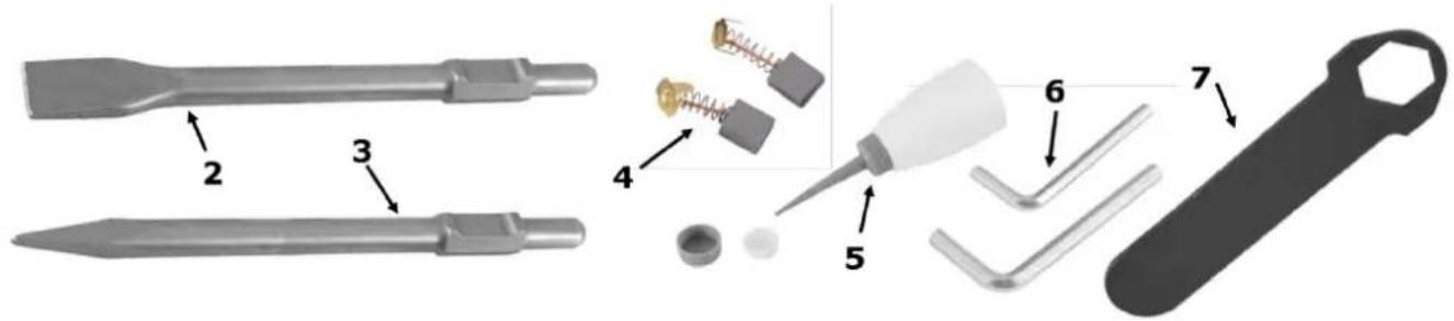
| 2 | Flat chisel | 5 | Oil filler |
| 3 | Point chisel | 6 | Allen key |
| 4 | Carbon brushes | 7 | Spanner |
10.3 Technical details
| ZI-ABH1500D | ZI-ABH1700D | |
| Voltage | 230 V / 50 Hz | 230 V / 50 Hz |
| Motor power | 1500 W | 1700 W |
| Hits / minute | 1900 | 1900 |
| Weight | 14 kg | 18,5 kg |
| Single hit power | 45 J | 65 J |
| Sound-pressure level L_PA (K=3dB(A)) | 93 dB(A) | 84,77 dB(A) |
| Sound-power level L_WA (K=3dB(A)) | 105 dB(A) | 105 dB(A) |
| Vibration a_h, C_Heq (K=1,5 m/s ^2 ) | 20,706 m/s ^2 | 21,343 m/s ^2 |
| Tool dimensions | 30x410mm (hexagonal) | 30x410mm (hexagonal) |
| Protection class | II | II |
| Protection mode | IP 20 | IP 20 |
The declared vibration total value has been measured in accordance with a standard test method and may be used for comparing one tool with another.
The declared vibration total value may also be used in a preliminary assessment of exposure.
WARNING
The vibration emission during actual use of the power tool can differ from the declared total value depending on the ways in which the tool is use!
11 SAFETY
11.1 Intended Use
The machine must only be used for its intended purpose! Any other use is deemed to be a case of misuse.
To use the machine properly you must also observe and follow all safety regulations, the assembly instructions, operating and maintenance instructions lay down in this manual.
All people who use and service the machine have to be acquainted with this manual and must be informed about the machine's potential hazards.
It is also imperative to observe the accident prevention regulations in force in your area.
The same applies for the general rules of occupational health and safety.
The machine is used for:
Chiselling in concrete, brick and stone.
Any manipulation of the machine or its parts is a misuse, in this case ZIPPER-MASCHINEN and its sales partners cannot be made liable for ANY direct or indirect damage.

WARNING
- Use only chisels allowable for this machine!
- Never use a damaged chisel!
- Use the machine never with defective or without mounted guard HIGHEST RISK OF INJURY!
Ambient conditions
The machine may be operated:
humidity
max. 70%
temperature
+5°C to +40°C (+41°F to +104°F)
The machine shall not be operated in areas exposed to increased fire or explosion hazard.
Prohibited use
- The operation of the machine outside the stated technical limits described in this manual is forbidden.
• The use of the machine not according with the required dimensions is forbidden. - The use of the machine not being suitable for the use of the machine and not being certified is forbidden.
- Any manipulation of the machine and parts is forbidden.
• The use of the machine for any purposes other than described in this manual is forbidden.
• The unattended operation on the machine during the working process is forbidden! - It is not allowed to leave the immediate work area during the work is being performed. Security instructions
Missing or non-readable security stickers have to be replaced immediately!
The locally applicable laws and regulations may specify the minimum age of the operator and limit the use of this machine!
To avoid malfunction, machine defects and injuries, read the following security instructions!

- Keep your work area dry and tidy! An untidy work area may cause accidents. Avoid slippery floor.

- Make sure the work area is lighted sufficiently

- Do not overload the machine

- Provide good stability and keep balance all times

- Avoid abnormal working postures! Make sure you stand squarely and keep balance at all times.

- Keep away from the running tool!

- Always stay focused when working. Reduce distortion sources in your working environment. The operation of the machine when being tired, as well as under the influence of alcohol, drugs or concentration influencing medicaments is forbidden.

• Respectively trained people only and only one person shall operate the machine.

- Do not allow other people, particularly children, to touch the machine or the cable. Keep them away from your work area.

- Make your workshop childproof.
- Avoid body contact with earthed
• Before starting the machine remove any adjusting wrenches and screwdrivers - Parts can cause severe cut injuries
- Keep the chisels sharp and clean, so they get stuck less often and are easier to guide
- Keep any machine that is not being used out of reach of children
11.2 Remaining risk factors

WARNING
It is important to ensure that each machine has remaining risks. In the execution of all work (even the simplest) greatest attention is required. A safe working depends on you!
Even if the machine is used as required it is still impossible to eliminate certain residual risk factors totally. The following hazards may arise in connection with the machine's construction and design:
• Risk of injury to the hands / fingers by the tool and tool mount during operation.
- Risk of injury due to sharp edges of the workpiece, especially in non-fixed with a suitable tool / device workpiece.
- Risk of injury: hair and loose clothing, etc. can be captured and wound up! Safety regulations must be observed with regard to clothing.
- Risk of injury due to contacting with live electrical components.
• Risk of injury due to dust emissions, treated with harmful agents workpieces
• Risk of injury to the hearing by prolonged labor without hearing protection
• Risk of injury to the eye by flying debris, even with safety goggles.
• Health damage caused by hand-arm vibrations if the equipment is used over a prolonged period or is not properly guided and maintained.
These risk factors can be minimized through obeying all security and operation instructions, proper machine maintenance, proficient and appropriate operation by persons with technical knowledge and experience.
12 OPERATION
Device to be operated in a perfect state only. Inspect the device visually every time it is to be used. Check in particular the safety equipment, electrical controls, electric cables and screwed connection for damage and if tightened properly. Replace any damaged parts before operating the device.
12.1 Operation instructions

WARNING
Perform all machine settings with the machine being disconnected from the power supply!

ATTENTION
Excessive pressure may cause material damage!
- When chiselling only slight pressure is required
- Too much pressure unnecessarily overload the motor and cause damage!

NOTICE
- Use auxiliary handles supplied with the tool Loss of control can cause personal injury
- Hold the machine by insulated gripping surface The contact with a live wire can cause electric shock
- Prior to chiselling into walls, ceilings or floors, ensure there are no electric cables or conduits inside.
- Checking the mains, whether they comply with the relevant national standards and guidelines (especially Assemblies for Construction Sites)
- Use only clean working tool. Lightly lubricate the chisel shank before use with a grease.
12.2 Operation
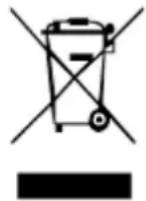
12.2.1 Insert chisel
Clean the tool shank of deposits and grease it lightly one.
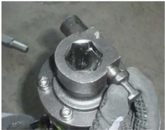
- The clamp bolt from the tool shaft pull and turn 90^ clockwise
natural_image
Close-up of a mechanical component with a hexagonal bolt and threaded shaft (no visible text or symbols)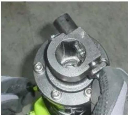
natural_image
Close-up of a mechanical component with metallic and green base, no visible text or symbols- Set the tool and rotate the clamp bolt back to 90 degrees and let it snap back into the tool shank.
- Check by pulling the tool if the tool is firmly held in place.
• Tool shank should always be greased before insertion. - When removing the tool. Follow the above procedure in reverse order.
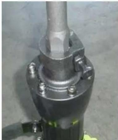
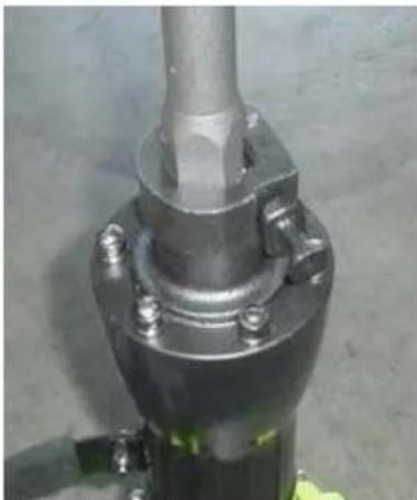
natural_image
Close-up of a metallic mechanical component with bolts and a cylindrical shaft (no visible text or symbols)12.2.2 Switch on
- Press the Power push button to the start the engine and set the stroke to move.
• By pressing the locking button can be switched to continuous operation.
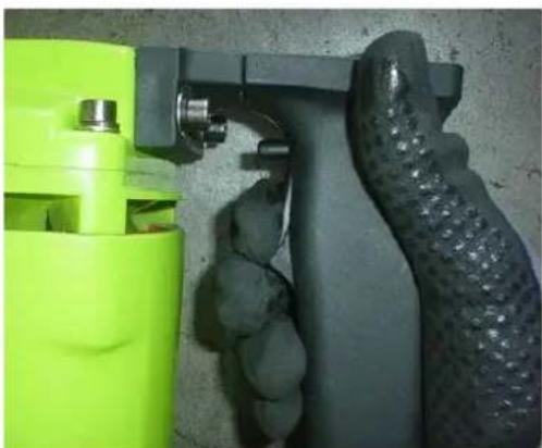
natural_image
Close-up of a hand holding a green spray gun and black textured object against a concrete wall (no text or symbols visible)
natural_image
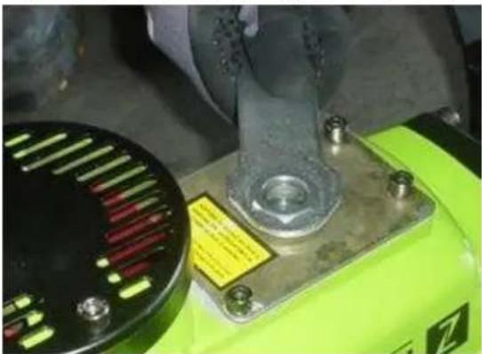
Close-up of a hand holding a green and black plastic tool, with no visible text or symbols.12.2.3 Switch off
• Take the pressure off switch push button to stop the stroke.
• For continuous operation, press and release the push button switch to release the fixation.
12.2.4 Filling with oil

WARNING
• The gear motor is supplied without oil!
- Fill gearbox-lubricating oil before starting the E-motor!
Before adding gearbox lubrication oil, disconnect the demolition hammer from the mains.
As an oil tank is installed, the demolition hammer can be used about 20 days to refill without oil. The daily use is about 3 - 4 hours.
Recommended gear oil: 15W40
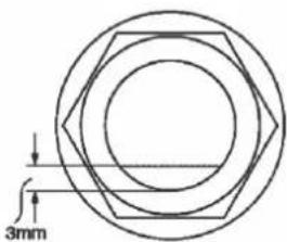
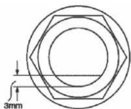
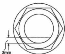
- Add oil, if in this position (or upright) in the oil level is less than 3mm, or no oil is visible.
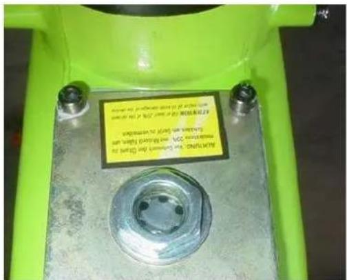
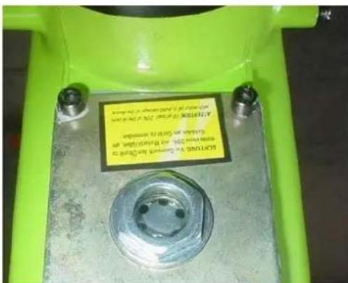
- Remove the oil level using the supplied Allen wrench. Make sure that the rubber seal on the thread fits well and is not damaged when screwing
natural_image
Close-up of a green industrial machine with a metallic bolt and a circular component, no visible text or symbols.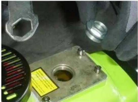
natural_image
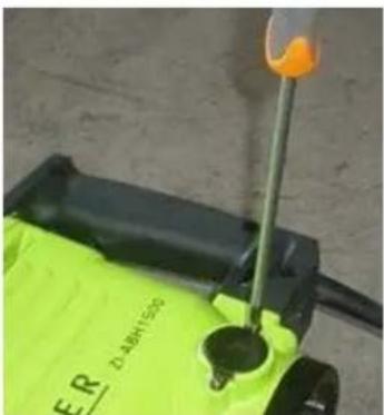
Close-up of a mechanical component with a metallic housing and bolted base, partially covered by gloved hands (no visible text or symbols)- To check, insert the oil level indicator and pull easily fixed.
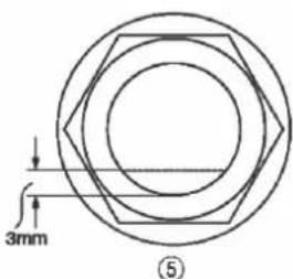
⑤
- Oil level should be around 3 mm from the lower edge
• After filling of oil drag the oil level again firmly
Perform all maintenance machine settings with the machine being disconnected from the power supply! Serious injury due to unintentional or automatic activation of the machine!

The machine does not require extensive maintenance. If malfunctions and defects occur, let it be serviced by trained persons only.
Before first operation as well as later on every 100 operation hours you should lubricate all connecting parts (if required, remove beforehand with a brush all swarfs and dust).
Check regularly the condition of the security stickers. Replace them if required.
Check regularly the condition of the machine.
The good condition and perfect adjustment of the guiding rollers is essential for a smooth band guidance and a clean cut.
Store the machine in a closed, dry location.
NOTICE
Clean your machine regularly after every usage – it prolongs the machines lifespan and is a prerequisite for a safe working environment.
Repair jobs shall be performed by respectively trained professionals only!
13.1 Maintenance plan
| Inspections for the maintenance of the machine | |
| Loose or missing screws | Daily before starting |
| Damage to any part | Daily before starting |
| Clean the machine | Daily before starting |
| Filling with grease | Every 25 working hours |
| Check tool mount to wear of | Every 100 working hours |
| Change carbon brushes | Every 100 working hours |
13.2 Changing the carbon brushes
If the carbon brushes are worn down to the wear limit may result in engine damage. Both carbon brushes should be replaced together. The procedure is ident in both models.
- Loosen the screws of the cover M4X12.
• Take off the cover and unscrew the brush cap. - Remove the carbon brushes.
natural_image
Close-up of a green safety device with a yellow screwdriver inserted, no visible text or symbols
natural_image
Close-up of a green industrial machine component with a metal clamp and cylindrical housing (no visible text or symbols)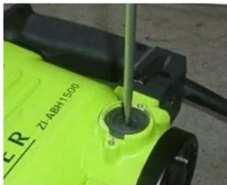
natural_image
Close-up of a green industrial water heater with a screwdriver inserted, no visible text or symbols on the device itself.• After replacing the carbon brushes rotate the brush cap back on.
- Screw the cover back on.
13.3 Cleaning
After each workshift the machine has to be cleaned. Remove chips etc. with a suitable tool. Do not remove them by hand (cutting injury!). Remove dust as well.

NOTICE
The usage of certain solutions containing ingredients damaging metal surfaces as well as the use of scrubbing agents will damage the machine surface!
Clean the machine surface with a wet cloth soaked in a mild solution
13.4 Disposal
Do not dispose the machine in residual waste. Contact your local authorities for information regarding the available disposal options. When you buy at your local dealer for a replacement unit, the latter is obliged to exchange your old.
14 TROUBLE SHOOTING
Disconnect the machine from the power supply prior to any checks performed at the machine itself!
| Trouble | Possible cause | Solution |
| Machine stops or will not start | Machine unpluggedCord damagedOverload tripped | Check all power connectionsChange cableAllow motor to cool and reset by pushing off switch |
| Impact system blocks | High fat friction due to low temperaturesMoving parts are blocked | Warm up the machine in a warm environmentChange damaged parts |
| Drill stucks | Disruptive reinforced steel | Fix new hole |
MANY MALFUNCTIONS AND DEFECTS CAN BE AVOIDED BY LETTING THE MACHINE BE CONNECTED TO YOUR POWER SUPPLY BY A CERTIFIED ELECTRICIAN

NOTICE
Should you in necessary repairs not able to properly to perform or you have not the prescribed training for it always attract a workshop to fix the problem.
15 PRÉFACE (FR)
Cher client!
natural_image
Close-up of a mechanical component with a hexagonal nut and bolted base, held by gloved hands (no visible text or symbols)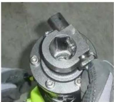
natural_image
Close-up of a mechanical component with bolts and a central hexagonal hole, partially covered by gloved hands (no visible text or symbols)natural_image
Close-up of a mechanical device with green and black components, no visible text or symbols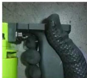
natural_image
Close-up of a hand holding a green and black plastic object, no visible text or symbolsnatural_image
Close-up of a mechanical device with a metallic bolt and green base, showing a tool interacting with it (no visible text or symbols)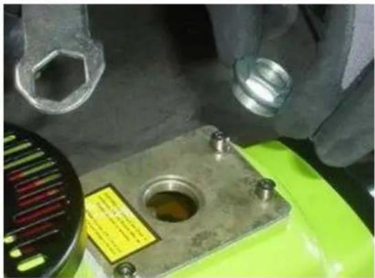
natural_image
Close-up of a mechanical component with a green base and metal housing, hands adjusting parts (no visible text or symbols)natural_image
Illustration of a laboratory instrument with labeled parts (no text or symbols present)19 MAINTENANCE

ATTENTION
natural_image
Close-up of a green electric shaver with a screwdriver inserted, no visible text or symbols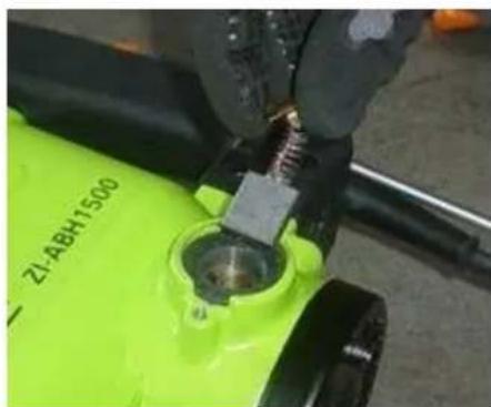
natural_image
Close-up of a green industrial machine component being adjusted by a hand, no visible text or symbols on the device itself.
natural_image
Close-up of a green industrial water purifier with a metal screw inserted, no visible text or symbols on the device itself.natural_image
Close-up of a mechanical component with a hexagonal bolt and threaded shaft (no visible text or symbols)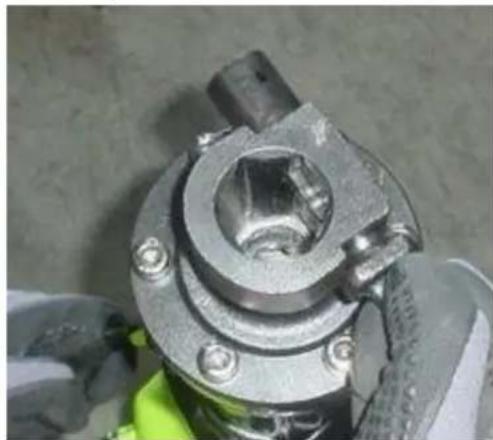
natural_image
Close-up of a mechanical component with bolts and a central hexagonal hole, partially covered by gloved hands (no visible text or symbols)- Vstavite orodje, zasučite zatič nazaj za 90° in pustite, da se orodje ujame v držalo orodja.
natural_image
Close-up of a mechanical component with a metallic cylindrical body and bolted flange (no visible text or symbols)24.2.2 Vklop
- Pritisnite tipko za vklop, da zaženete stroj in začnete z dolbenjem.
natural_image
Close-up of a hand gripping a green and black plastic object against a concrete wall (no text or symbols visible)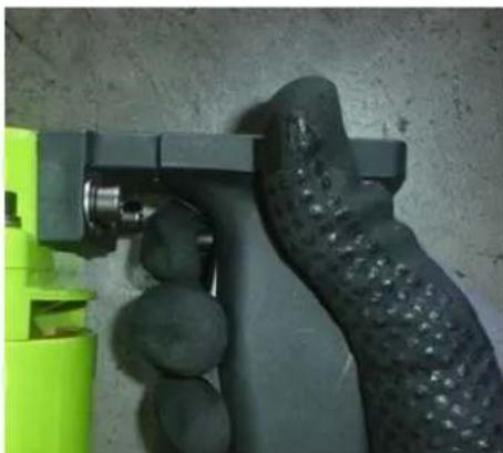
natural_image
Close-up of a hand holding a green and black mechanical device with circular components, against a plain concrete wall (no text or symbols visible)24.2.3 Izklop
- Prenehajte pritiskati na gumb za vklop, da zaustavite napravo.
• Pri neprekinjenem delu na kratko pritisnite tipko za vklop, da sprostite fiksiranje.
24.2.4 Vlivanje olja

POZOR!
- Vaš motor z vgrajenim rezervoarjem za olje je izdobavljen brez olja.
- Napolnite olje za pogon orodja, preden zaženete motor!
natural_image
Close-up of a green industrial machine with a metal bolt and yellow warning label (no readable text or symbols)
natural_image
Close-up of industrial machinery components including a metallic housing, bolted joints, and a green base (no visible text or symbols)• Preverite, će ste vlili dovolj olja tako, da vstavite prikaz nivoja olja in lahno zategnete.
⑤
• Nivo olja mora biti ca. 3 mm od spodnjega roba
• Po polnjenju mazalnega olja spet dobro zategnite prikaz nivoja olja.
25 VZDRŽEVANJE

POZOR!
natural_image
Close-up of a green ER water heater with a screwdriver inserted, no visible text or symbols on the device itself.
natural_image
Close-up of a green industrial machine component with a metal screw and central hub (no visible text or symbols)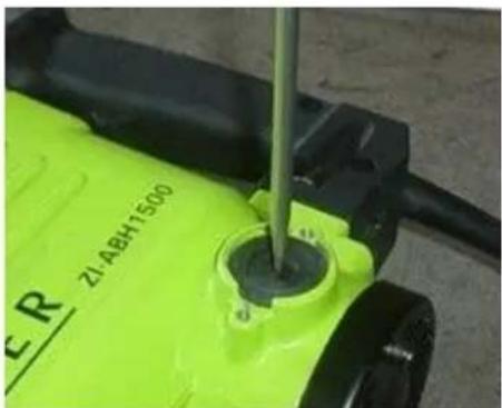
natural_image
Close-up of a green industrial water heater with a screwdriver inserted, no visible text or symbols on the device itself.| 2 | Plosnato dlijeto | 5 | Lijevak za ulje |
| 3 | Šiljato dlijeto | 6 | Imbus ključ |
| 4 | Rezervne ugljene četke | 7 | Ključ za vijke |
natural_image
Close-up of a metallic mechanical component with a hexagonal bolt and threaded shaft (no visible text or symbols)
natural_image
Close-up of a mechanical component with bolts and a central hub, partially covered by gloved hands (no visible text or symbols)- Umetnite alat i stezni svornjak okrenite za 90° te pustite da zahvati u prihvatu alata.
natural_image
Close-up of a metallic mechanical valve or fitting with bolted components (no visible text or symbols)30.2.2 Uključivanje
natural_image
Close-up of a green spray gun with attached black rubber head and metal fittings (no text or symbols visible)
natural_image
Close-up of a hand holding a green and black handheld device against a textured concrete wall (no visible text or symbols)natural_image
Close-up of a mechanical device with a metallic bolt and green base, no visible text or symbols
natural_image
Close-up of a mechanical component with a green base and metallic housing, no visible text or symbols- Za provjeru stavite prikaz razine ulja i lagano ga zategnite.

⑤
natural_image
Close-up of a green and black electric water heater with a screwdriver inserted, no visible text or symbols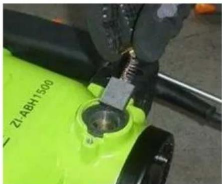
natural_image
Close-up of a green industrial machine component with a metal screw and cylindrical housing (no visible text or symbols)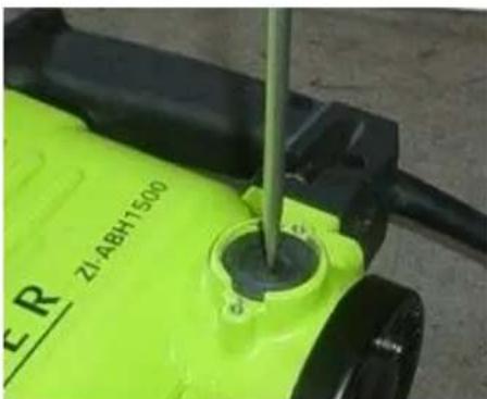
natural_image
Close-up of a green industrial water heater with a screwdriver inserted, no visible text or symbols on the device itself.| 2 | Sekač | 5 | Levak za ulje |
| 3 | Špic | 6 | Imbus ključ |
| 4 | Rezervne ugljene četke | 7 | Ključ za vijke |
natural_image
Close-up of a metallic mechanical component with hexagonal bolt and threaded shaft (no visible text or symbols)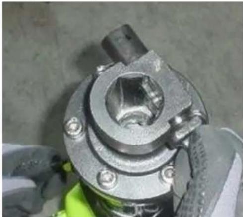
natural_image
Close-up of a mechanical component with bolts and a central hub, partially covered by gloved hands (no visible text or symbols)- Umetnite alat i stezni vijak okrenite za 90° te pustite da zahvati u prihvatu alata.
- Izvlačenjem alata proverite da li čvrsto naleže.
• Za uklanjanje alata postupajte obrnutim redosledom
natural_image
Close-up of a metallic mechanical component with bolted flange and bolted end (no visible text or symbols)36.2.2 Uključivanje
natural_image
Close-up of a green spray gun with attached black rubber hose, no visible text or symbols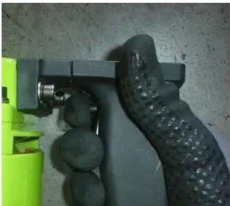
natural_image
Close-up of a hand holding a green and black plastic tool against a textured wall (no text or symbols visible)natural_image
Close-up of a mechanical device with a metallic bolt and screw base, no visible text or symbols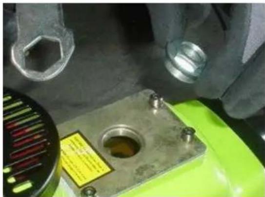
natural_image
Close-up of industrial machinery components including a metal mounting bracket and bolts, with no visible text or symbols.- Za proveru stavite prikaz nivoa ulja i lagano ga zategnite.
⑤
• Nivo ulja treba biti oko 3mm od donjeg ruba

natural_image
Close-up of a green and black device with a yellow screwdriver inserted, no visible text or symbols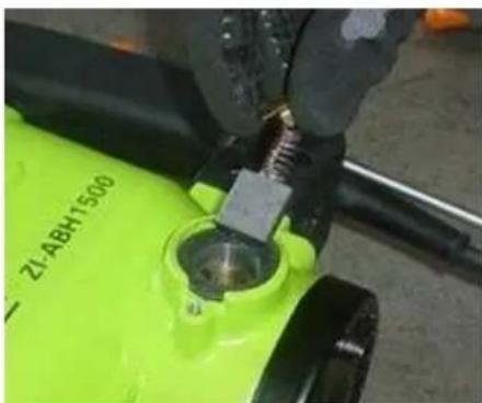
natural_image
Close-up of a green industrial machine component being adjusted by a hand, no visible text or symbols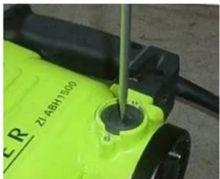
natural_image
Close-up of a green CR water heater with a screwdriver inserted, showing internal components (no readable text or symbols)• Nakon zamene ugljenih četki opet zavrnite kapicu četkica
- Opet zavrnite poklopac.
37.3 Čišćenje
Nakon svakog stavljanja u pogon mašinu i sve negove delove treba temeljno očistiti.
Mašinu nakon rada redovno čistite od strugotina i prašine od bušenja.

NAPOMENA
Upotreba otapada, agresivnih hemikalija ili abrazivnih sredstava dovodi do materijalne štete na mašini!
Prilikom čišćenja koristite samo vodu i po potrebi blaga sredstva za čišćenje!
37.4 Odlaganje
natural_image
Close-up of a metallic mechanical component with bolts and a hexagonal nut, held by gloved hands (no visible text or symbols)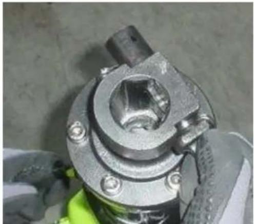
natural_image
Close-up of a mechanical component with metallic parts and bolts, no visible text or symbolsnatural_image
Close-up of a metallic mechanical component with flanged ends and bolted joints (no visible text or symbols)42.2.2 Accendere
natural_image
Close-up of a hand holding a green spray gun and black textured object against a concrete wall (no text or symbols visible)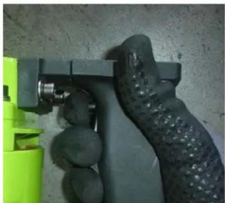
natural_image
Close-up of a hand holding a green and black plastic tool against a textured concrete wall (no text or symbols visible)42.2.3 Spegnere
natural_image
Close-up of a mechanical device with a metallic bolt and green base, showing a yellow label on the component (no readable text or symbols)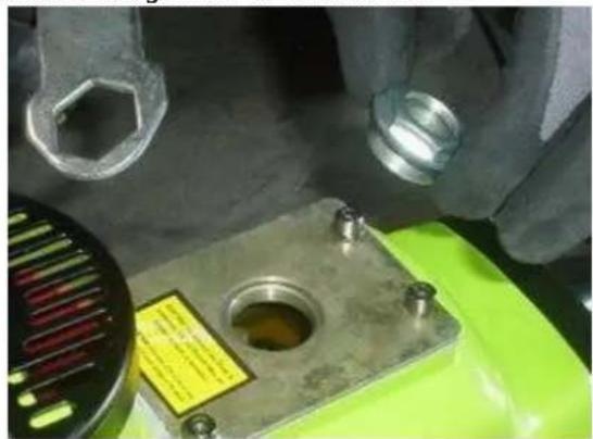
natural_image
Close-up of hands assembling a mechanical component with a green base and a yellow label (no visible text or symbols)natural_image
Close-up of a green and black electric shaver with a screwdriver inserted, no visible text or symbols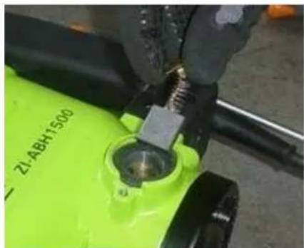
natural_image
Close-up of a green industrial machine component with a metal screw and cylindrical housing (no visible text or symbols)
natural_image
Close-up of a green industrial machine with a screwdriver inserted, no visible text or symbols on the device itself.natural_image
Close-up of a metallic mechanical component with bolts and a hexagonal nut (no visible text or symbols)
natural_image
Close-up of a mechanical component with bolts and a central hexagonal hole, partially covered by gloved hands (no visible text or symbols)natural_image
Close-up of a hand holding a spray gun and a black textured object, next to a green safety container (no visible text or symbols)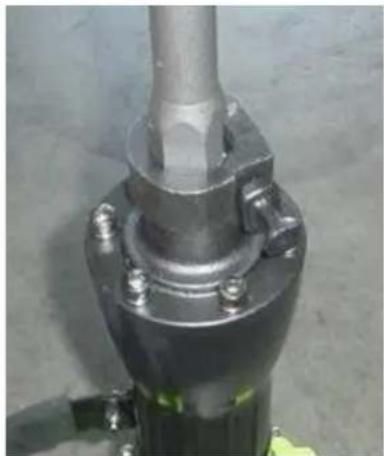
natural_image
Close-up of a metallic mechanical component with bolts and a central shaft (no visible text or symbols)
natural_image
Close-up of a green and black handheld device with textured grip, mounted on a wall (no visible text or symbols)48.2.3 Vypnutí
natural_image
Close-up of a green industrial machine with a metallic screw and a black circular component, no visible text or symbols.
natural_image
Close-up of a mechanical component with a green base, bolt holes, and a yellow label (no readable text or symbols)49 ÚDRŽBA

POZOR
natural_image
Close-up of a green electric shock absorber with a screwdriver inserted, showing orange liquid (no text or symbols visible)
natural_image
Close-up of a green industrial machine component being adjusted by a hand using a tool (no visible text or symbols)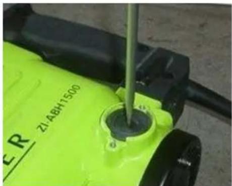
natural_image
Close-up of a green electric water heater with a screwdriver inserted, showing no visible text or symbols on the device itself.natural_image
Close-up of a mechanical component with a hexagonal bolt and threaded shaft (no visible text or symbols)
natural_image
Close-up of a mechanical component with bolts and a central hexagonal hole, partially covered by gloved hands (no visible text or symbols)natural_image
Close-up of a mechanical component with a metallic shaft and flange (no visible text or symbols)natural_image
Close-up of a hand holding a green spray gun and black textured object against a concrete wall (no text or symbols visible)
natural_image
Close-up of a hand holding a green and black plastic tool against a textured concrete wall (no text or symbols visible)54.2.3 Vypnutie
natural_image
Close-up of a green industrial machine with a metallic bolt and circular component, no visible text or symbols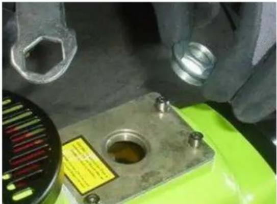
natural_image
Close-up of a mechanical component with bolts and a yellow label, partially mounted on a green base (no visible text or symbols)- Ku kontrole nasadte kontrolné sklíčko a dotiahnite.
55 ÚDRŽBA

POZOR
natural_image
Close-up of a green industrial water heater with a yellow tool inserted, showing internal components and a small orange object (no readable text or symbols)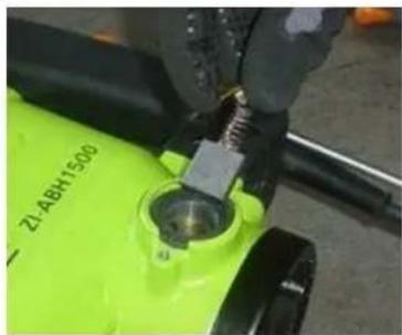
natural_image
Close-up of a green industrial machine component with a metallic tool inserted, no visible text or symbols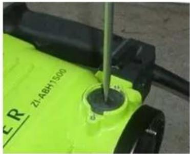
natural_image
Close-up of a green industrial water heater with a metal screwdriver inserted, no visible text or symbolsnatural_image
Close-up of a mechanical component with a hexagonal bolt and threaded shaft (no visible text or symbols)
natural_image
Close-up of a mechanical component with bolts and a central hole, partially covered by gloved hands (no visible text or symbols)natural_image
Close-up of a metallic mechanical component with bolted flange and bolt holes (no visible text or symbols)60.2.2 Bekapcsolás
natural_image
Close-up of a green and black plastic tool with a textured grip, mounted on a wall (no visible text or symbols)
natural_image
Close-up of a hand holding a green and black plastic tool against a textured wall (no text or symbols visible)60.2.3 Kikapcsolás
natural_image
Close-up of a mechanical device with a metallic bolt and green base, no visible text or symbols
natural_image
Close-up of industrial machinery components with a green base and metal housing, no visible text or symbolsnatural_image
Close-up of a green safety device with a yellow-orange probe inserted, no visible text or symbols•

natural_image
Close-up of a green industrial machine component with a metallic screw and cylindrical housing (no visible text or symbols)• A

natural_image
Close-up of a green industrial machine with a screwdriver inserted, no visible text or symbols on the device itself.natural_image
Close-up of a mechanical component with a hexagonal bolt and threaded shaft, held by gloved hands (no visible text or symbols)
natural_image
Close-up of a mechanical component with metallic parts and bolts, no visible text or symbolsnatural_image
Close-up of a metallic mechanical component with bolted flange and bolted end (no visible text or symbols)66.2.2 Encendido
natural_image
Close-up of a hand gripping a green plastic lever and black textured object against a concrete wall (no text or symbols visible)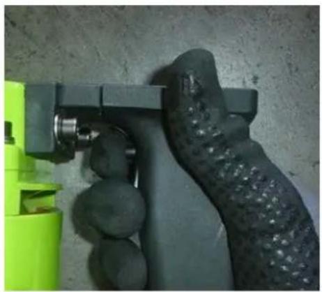
natural_image
Close-up of a hand holding a green and black handheld device against a textured gray wall (no visible text or symbols)66.2.3 Apagado
natural_image
Close-up of a green industrial machine with a metal base and screw bolts, no visible text or symbols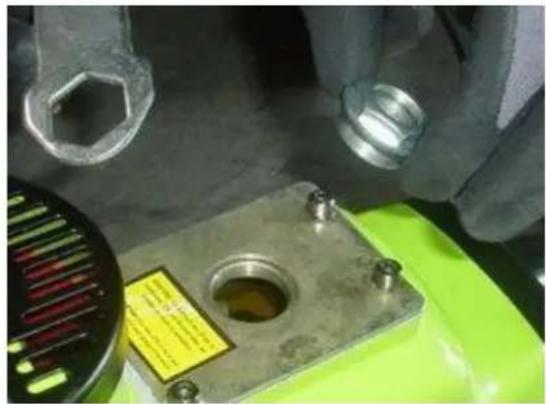
natural_image
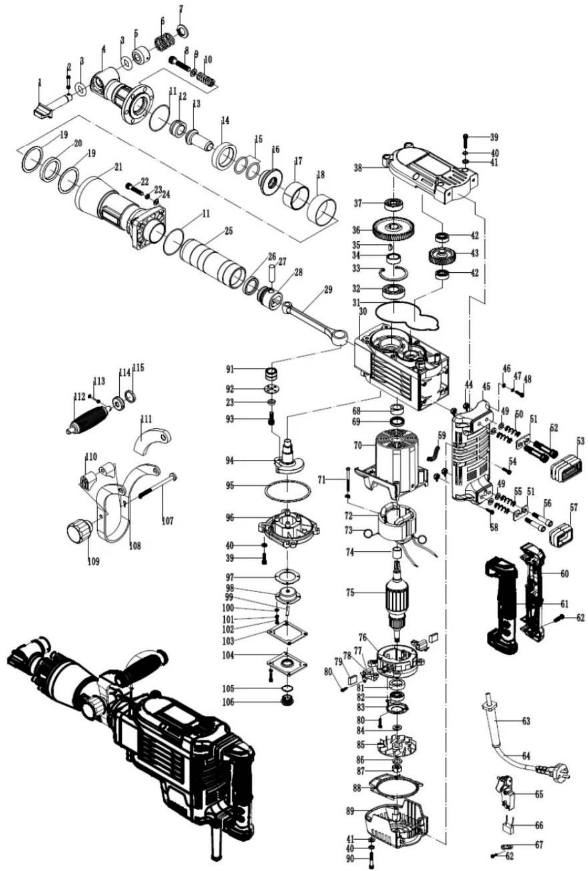
Close-up of a mechanical component with a green base and yellow label, hands visible adjusting parts (no readable text or symbols)With original ZIPPER spare parts you use parts that are attuned to each other shorten the installation time and elongate your machines lifespan.
IMPORTANT
The installation of other than original spare parts voids the warranty!
So you always have to use original spare parts
When you place a spare parts order please use the service formular you can find in the last chapter of this manual. Always take a note of the machine type, spare parts number and partname. We recommend to copy the spare parts diagram and mark the spare part you need.
You find the order address in the preface of this operation manual.
| 1 | washer 12.5x18x0.8 | 1 | 51 | nylock hex.socket bolt M6x14 | 2 |
| 2 | washer 12.4x17.6x2.6 | 1 | 52 | rotor | 1 |
| 3 | spring 17.5x1.3x26.5 | 1 | 53 | bearing 6201-2rs | 1 |
| 4 | spring case 23x28 | 1 | 54 | washer 31x25x0.5 | 1 |
| 5 | pin ∅ 4x18 | 1 | 55 | stator | 1 |
| 6 | nylock hex.socket bolt M10x35 | 6 | 56 | hex.socket ST4.8x60 | 2 |
| 7 | washer 10 | 12 | 57 | ststor housing | 1 |
| 8 | stop lever | 1 | 58 | switch | 1 |
| 9 | block blessing | 1 | 59 | handle | 1 |
| 10 | damper 47.5x66.5x14.3 | 1 | 60 | handle cover | 1 |
| 11 | o-ring 23.6x5 | 1 | 61 | nylock hex.socket bolt M6x25 | 4 |
| 12 | shank sleeve | 1 | 62 | self-tapping screw ST3.9x20 | 3 |
| 13 | ring | 1 | 63 | capacitance 0.33μf | 1 |
| 14 | ring 64.5x67.5x27.5 | 1 | 64 | cable plate | 1 |
| 15 | ring 68.4x57.6x2 | 2 | 65 | nylock hex.socket bolt M3.9x14 | 2 |
| 16 | damper 58x68x9.3 | 1 | 66 | cable cover | 1 |
| 17 | cylinder house | 1 | 67 | cable | 1 |
| 18 | nylock hex.socket bolt M8x35 | 4 | 68 | chassis | 1 |
| 19 | washer8 | 5 | 69 | nylock hex.socket bolt M5x12 | 6 |
| 20 | washer8 | 4 | 70 | spring | 2 |
| 21 | o-ring ∅ 58x ∅ 2 | 1 | 71 | brush washer | 2 |
| 22 | cylinder | 1 | 72 | brush holder | 2 |
| 23 | o-ring | 1 | 73 | nylock hex.socket bolt M5x8 | 2 |
| 24 | piston | 1 | 74 | carton brush | 2 |
| 25 | pin 12x44 | 1 | 75 | brush holder cap | 2 |
| 26 | connecting rod | 1 | 76 | washer 10x26x3 | 2 |
| 27 | pin ∅ 5x14 | 2 | 77 | brush cover | 2 |
| 28 | housing | 1 | 78 | washer 4 | 4 |
| 29 | ring | 1 | 79 | hex.socket ST4x16 | 8 |
| 30 | crankshaft 26.5 | 1 | 80 | oil gauge | 1 |
| 31 | key 4x16 | 2 | 81 | o-spring W 23x2 | 1 |
| 32 | nylock hex.socket bolt M5x25 | 7 | 82 | oil box cover | 1 |
| 33 | washer 5 | 13 | 83 | washer | 1 |
| 34 | bearing board | 1 | 84 | washer4 | 4 |
| 35 | bearing 6205 | 1 | 85 | felt holder | 1 |
| 36 | inner cover | 1 | 86 | oil felt | 1 |
| 37 | ring 22.5x34x7.5 | 1 | 87 | o-ring | 1 |
| 38 | gear 73 | 1 | 88 | nylock hex.socket bolt M8x30 | 1 |
| 39 | ring 22 | 1 | 89 | board 34x2.3 | 1 |
| 40 | bearing 6302 | 1 | 90 | needle bearing NK18/20 | 1 |
| 41 | gear cover | 1 | 91 | bolted joint M8x110 | 1 |
| 42 | nylock hex.socket bolt M6x45 | 6 | 92 | hand seat | 2 |
| 43 | washer 6 | 10 | 93 | hand grip | 1 |
| 44 | washer 6 | 10 | 94 | knob | 1 |
| 45 | bearing 6201 | 1 | 95 | rubber sleeve | 2 |
| 46 | gear 43 | 1 | 96 | handshaft | 2 |
| 47 | bearing 6001 | 1 | 97 | handshaft ∅ 32.5x23.5x4.5 | 2 |
| 48 | bearing cover(6203) | 1 | 98 | pin | 2 |
| 49 | 6203 bearing washer 29.4x40x2.2 | 1 | 99 | auxiliary | 1 |
| 50 | bearing 6203 | 1 |
70.2.2 ZI-ABH1700D
| 1 | lock rod | 1 | 59 | insulation tube | 1 |
| 2 | round pin | 1 | 60 | right handle | 1 |
| 3 | o-ring 18x8 | 2 | 61 | left handle | 1 |
| 4 | headstrong | 1 | 62 | screw ST3.9x16 | 7 |
| 5 | lock rod cover | 1 | 63 | cable sleeve | 1 |
| 6 | spring | 1 | 64 | cable 2 × 1 mm^2 | 1 |
| 7 | washer | 1 | 65 | switch | 1 |
| 8 | screw M10x65 | 6 | 66 | capacitance | 1 |
| 9 | washer 10 | 6 | 67 | cable board | 1 |
| 10 | spring | 6 | 68 | bearing NK18/20 | 1 |
| 11 | o-ring 60x2 | 2 | 69 | oil seal | 1 |
| 12 | ram hammer cover | 1 | 70 | chassis | 1 |
| 13 | ram hammer | 1 | 71 | screw | 2 |
| 14 | damper ø47.5x ø 66.5x14.3 | 1 | 72 | stator | 1 |
| 15 | o-ring 18 x 8 | 1 | 73 | tension spring | 2 |
| 16 | aluminum sleeve | 1 | 74 | washer | 1 |
| 17 | split sleeve | 1 | 75 | rotor | 1 |
| 18 | split sleeve cover | 1 | 76 | brush | 1 |
| 19 | washer ø 57.5x ø 68.4x2 | 2 | 77 | brush holder | 2 |
| 20 | damper ø 58x ø 68x9.3 | 1 | 78 | coil spring | 2 |
| 21 | cylinder house | 1 | 79 | brush | 2 |
| 22 | seal look hex. socket hd. bolt | 4 | 80 | screw | 4 |
| 23 | spring washer 8 | 5 | 81 | bearing sleeve | 1 |
| 24 | plat washer 8 | 4 | 82 | bearing 6201-2RS | 1 |
| 25 | cylinder | 1 | 83 | bearing board | 1 |
| 26 | piston seal | 1 | 84 | washer | 1 |
| 27 | piston pin | 1 | 85 | fan | 1 |
| 28 | position | 1 | 86 | washer 12 | 1 |
| 29 | connecting rod | 1 | 87 | nut M12 x 1.25 | 1 |
| 30 | gear box | 1 | 88 | fan guide | 1 |
| 31 | oil ring | 1 | 89 | chassis | 1 |
| 32 | bearing 6205-2RS | 1 | 90 | screw M8 x 75 | 4 |
| 33 | washer 52 | 1 | 91 | bearing NK18/20 | 1 |
| 34 | range ring | 1 | 92 | bearing cover 24.5 x 2.3 | 1 |
| 35 | woodruff key | 2 | 93 | screw M8 x 10 | 1 |
| 36 | gear 63 | 1 | 94 | crankshaft | 1 |
| 37 | bearing 6205-2RZ | 1 | 95 | oil seal | 1 |
| 38 | cover | 1 | 96 | oil house | 1 |
| 39 | seal look hex. socket hd. bolt | 10 | 97 | felt holder seal | 1 |
| 40 | plat washer 6 | 14 | 98 | felt holder | 1 |
| 41 | spring washer 6 | 10 | 99 | oil felt 7 x 70 | 1 |
| 42 | bearing 6201-2RZ | 2 | 100 | washer | 4 |
| 43 | gear 37 | 1 | 101 | washer | 4 |
| 44 | nut | 4 | 102 | screw | 4 |
| 45 | handle holder | 1 | 103 | washer | 1 |
| 46 | flat washer 5 | 2 | 104 | oil box cover | 1 |
| 47 | spring | 2 | 105 | o-ring W23 x 2 | 1 |
| 48 | nylock hex.socket hd.bolt M5x16 | 2 | 106 | oil gauge | 1 |
| 49 | flat washer 8 | 4 | 107 | nut M8 x 10 | 1 |
| 50 | damping spring | 2 | 108 | hand grip | 1 |
| 51 | damping board | 2 | 109 | knob | 1 |
| 52 | damping screw | 4 | 110 | plastic block | 2 |
| 53 | upper damping sleeve | 2 | 111 | rubber cover | 2 |
| 54 | nylock hex.socket hd.bolt M5x22 | 2 | 112 | auxiliary handle | 1 |
| 55 | damping spring | 2 | 113 | round pin | 2 |
| 56 | damping screw | 2 | 114 | handshaft | 2 |
| 57 | under damping spring | 1 | 115 | handshaft cover | 2 |
| 58 | screw ST4.8 x 25 | 2 |
Company ZIPPER Maschinen GmbH grants for mechanical and electrical components a warranty period of 2 years for amateur use; and warranty period of 1 year for professional use, starting with the purchase of the final consumer. In case of defects during this period, which are not excluded by paragraph 3, ZIPPER will repair or replace the machine at its own discretion.
2.) Report:
In order to check the legitimacy of warranty claims, the final consumer must contact his dealer. The dealer has to report in written form the occurred defect to ZIPPER. If the warranty claim is legitimate, ZIPPER will pick up the defective machine from the dealer. Returned shippings by dealers which have not been coordinated with ZIPPER, will not be accepted and refused.
3.) Regulations:
a) Warranty claims will only be accepted, when a copy of the original invoice or cash voucher from the trading partner of ZIPPER is enclosed to the machine. The warranty claim expires if the accessories belonging to the machine are missing.
b) The warranty does not include free checking, maintenance, inspection or service works on the machine. Defects due to incorrect usage of the final consumer or his dealer will not be accepted as warranty claims either. Some examples: usage of wrong fuel, frost damages in water tanks, leaving fuel in the tank during the winter, etc.
c) Defects on wear parts are excluded, e.g. carbon brushes, collection bags, knives, cylinders, cutting blades, clutches, sealings, wheels, saw blades, splitting crosses, riving knives, riving knife extensions, hydraulic oils, oil/air/fuel filters, chains, spark plugs, sliding blocks, etc.
d) Also excluded are damages on the machine caused by incorrect or inappropriate usage, if it was used for a purpose which the machine is not supposed to, ignoring the user manual, force majeure, repairs or technical manipulations by not authorized workshops or by the customer himself, usage of non-original ZIPPER spare parts or accessories.
e) After inspection by our qualified personnel, resulted costs (like freight charges) and expenses for not legitimated warranty claims will be charged to the final customer or dealer.
f) In case of defective machines outside the warranty period, we will only repair after advance payment or dealer's invoice according to the cost estimate (incl. freight costs) of ZIPPER.
g) Warranty claims can only be granted for customers of an authorized ZIPPER dealer who directly purchased the machine from ZIPPER. These claims are not transferable in case of multiple sales of the machine.
4.) Claims for compensation and other liabilities:
The liability of company ZIPPER is limited to the value of goods in all cases. Claims for compensation because of poor performance, lacks, damages or loss of earnings due to defects during the warranty period will not be accepted. ZIPPER insists on its right to subsequent improvement of the machine.
74 GARANTIE ET SERVICE (FR)
1.) Garantie:
Product experience form
We observe the quality of our delivered products in the frame of a Quality Management policy.
Your opinion is essential for further product development and product choice. Please let us know about your:
- Impressions and suggestions for improvement.
- experiences that may be useful for other users and for product design
- Experiences with malfunctions that occur in specific operation modes
We would like to ask you to note down your experiences and observations and send them to us via FAX, E-Mail or by post:
Erworben von / purchased from:
E-Mail/ e-mail:
Please describe amongst others in the problem: What has cause the problem/defect, what was the last activity before you noticed the problem/defect? For electrical problems: Have you had checked you electric supply and the machine already by a certified electrician?
3. Bitte beachten
/ Additional information
INCOMPLETELY FILLED SERVICE FORMS CANNOT BE PROCESSED! FOR GUARANTEE CLAIMS PLEASE ADD A COPY OF YOUR ORIGINAL SALES / DELIVERY RECEIPT OTHERWISE IT CANNOT BE ACCEPTED. FOR SPARE PART ORDERS PLEASE ADD TO THIS SERVICE FORM A COPY OF THE RESPECTIVE EXPLODED DRAWING WITH THE REQUIRED SPARE PARTS BEING MARKED CLEARLY AND UNMISTAKABLE. THIS HELPS US TO IDENTIFY THE REQUIRED SPARE PARTS FASTLY AND ACCEL- LERATES THE HANDLING OF YOUR INQUIRY.

- INHALT / INDEX
- INHALT / INDEX 2
- OPERATION
- MAINTENANCE
- TROUBLE SHOOTING
- PREFACE (FR)
- TECHNIQUE
- Einschalten
- Ausschalten
- Please follow the security instructions!
- Copyright law
- Customer Support
- Delivery content
- Technical details
- WARNING
- SAFETY
- Intended Use
- Ambient conditions
- Prohibited use
- Missing or non-readable security stickers have to be replaced immediately!
- The locally applicable laws and regulations may specify the minimum age of the operator and limit the use of this machine!
- Remaining risk factors
- Operation instructions
- ATTENTION
- NOTICE
- Operation
- Insert chisel
- Switch on
- Switch off
- Filling with oil
- Maintenance plan
- Changing the carbon brushes
- Cleaning
- Disposal
- PRÉFACE (FR)
- Cher client!
- MAINTENANCE
- Vklop
- Izklop
- Vlivanje olja
- POZOR!
- VZDRŽEVANJE
- Uključivanje
- Uključivanje
- Čišćenje
- NAPOMENA
- Odlaganje
- Accendere
- Spegnere
- Vypnutí
- ÚDRŽBA
- POZOR
- Vypnutie
- ÚDRŽBA
- Bekapcsolás
- Kikapcsolás
- Encendido
- Apagado
- IMPORTANT
- The installation of other than original spare parts voids the warranty!
- 2.) Report:
- 3.) Regulations:
- 4.) Claims for compensation and other liabilities:
- GARANTIE ET SERVICE (FR)
- 1.) Garantie:
- Product experience form
- Bitte beachten
- / Additional information
Brand : Zipper
Model : ZIABH1500D
Category : Hammer