
VPLXW7000 - Projector SONY - Free user manual and instructions
Find the device manual for free VPLXW7000 SONY in PDF.
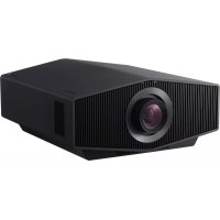



| Product type | Projector |
| Brand | Sony |
| Model | VPLXW7000 |
| Display technology | LCD |
| Light source | Laser diode (5.2 W × 24) |
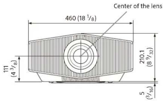
| Dimensions (W × H × D) | 460 mm × 210.1 mm × approx. 260 mm |
| Power supply | 100-240 V AC, 50/60 Hz |
| Connectivity | HDMI input, USB port, LAN port (Network) |
| Lens adjustments | Motorized: zoom, focus, shift |
| Preset picture modes | Cinema Film 1/2, Reference, TV, Photo, Game, Cinema Bright, TV Bright, User, IMAX Enhanced |
| Remote control | RM-PJ24 with AA batteries (supplied) |
| Lens cap | Supplied |
| Ceiling mount | Possible (installation by certified technician recommended) |
| Safety | Class 1 laser, do not look into the lens, avoid blocking vents |
| Exterior care | Clean with a soft, dry cloth; do not use solvents |
| Repairability | Refer to a certified Sony technician |
| Manuals supplied | Setup manual (paper), Online Help Guide |
| Warranty | Check the terms provided by your dealer |
Frequently Asked Questions - VPLXW7000 SONY
User questions about VPLXW7000 SONY
0 question about this device. Answer the ones you know or ask your own.
Ask a new question about this device
Download the instructions for your Projector in PDF format for free! Find your manual VPLXW7000 - SONY and take your electronic device back in hand. On this page are published all the documents necessary for the use of your device. VPLXW7000 by SONY.
USER MANUAL VPLXW7000 SONY
© 2022 Sony Corporation

About This Manual
This Setup Guide explains the installation and basic operations for projecting pictures.
Before operating the unit, please read this manual thoroughly and retain it for future reference.
Refer to "About Indicators" as necessary.
For details on the operations, refer to the Help Guide (Web operating instructions).
Step 1
Preparing Page 9
Step 2
Installing the Unit ......Page 10
Step 3
Connecting the Unit ...... Page 12
Step 4
Projecting...... Page 13
About Indicators......Page 14
Manuals supplied
Setup Guide (this document)
Explains the installation and basic operations for projecting pictures.

Help Guide (Web operating instructions)
Explains the features of the unit and how to use in detail. You can view the Help
Guide on a smartphone or computer.
https://rd1.sony.net/help/vpl/xw5000/en/
English
When using the product, do not use it for purposes other than those described in the instruction manual.
WARNING
To reduce the risk of fire or electric shock, do not expose this apparatus to rain or moisture. To avoid electrical shock, do not open the cabinet. Refer servicing to qualified personnel only.
WARNING
When installing the unit, incorporate a readily accessible disconnect device in the fixed wiring, or connect the power plug to an easily accessible socket-outlet near the unit. If a fault should occur during operation of the unit, operate the disconnect device to switch the power supply off, or disconnect the power plug.
CAUTION
For safety, do not connect the connector for peripheral device wiring that might have excessive voltage to the following port:
• LAN
WARNING
- Use the approved Power Cord (2-core mains lead) / Appliance Connector / Plug that conforms to the safety regulations of each country/region if applicable.
- Use the Power Cord (2-core mains lead) / Appliance Connector / Plug conforming to the proper ratings (Voltage, Ampere).
If you have questions on the use of the above Power Cord / Appliance Connector / Plug, please consult a qualified service personnel.
IMPORTANT
The nameplate is located in the following location on the unit.
- Side
CAUTION
- Danger of explosion if battery is incorrectly replaced. Replace only with the same or equivalent type recommended by the manufacturer.
- When you dispose of the battery or the product, you must obey the law in the corresponding area or country. Do not dispose of the battery or the
product in a fire or a hot oven, or mechanically crush or cut the battery. It may explode or cause a fire. Do not subject the battery to extremely low air pressure that may result in an explosion or the leakage of flammable liquid or gas.
- Do not place the battery in a high temperature place, such as under direct sunlight or near fire. It may ignite, explode, or cause a fire. Do not immerse or wet the battery in water or seawater. This may cause an electric shock.
CAUTION
The following size and number of batteries are required for the remote control.
- Size: AA (R6)
- Number of batteries: Two pieces To avoid risk of explosion, use only the following type of battery.
- Manganese batteries

This symbol is intended to alert the user to the presence of important operating and maintenance (servicing) instructions in the literature accompanying the appliance.
For customers in Norway
This equipment can be connected to an IT power distribution system.
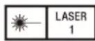
IEC 60825-1:2014
CLASS 1 LASER PRODUCT
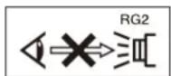
As with any bright light source, do not stare into the beam, RG2 IEC 62471-5:2015.
WARNING: Do not look into the lens while in use.
Caution
Use of controls or adjustments or performance of procedures other than those specified herein may result in hazardous radiation exposure.
Caution
The use of optical instruments with this product will increase eye hazard.
Location information of the labels
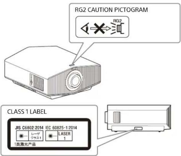
Light source specifications
5.2 W laser diodes × 24
Wavelength: 450 - 460 nm
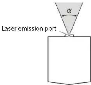
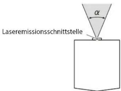
Beam divergence angle from lens of this unit
Zoom maximum: α = 39.9°
Zoom minimum: α = 25.5°
Do not place any object in front of the lens that may block the light during projection. Heat from the light may damage the object.
For the customers in the U.S.A.
SONY LIMITED WARRANTY - Please visit http://www.sony.com/psa/warranty for important information and complete terms and conditions of Sony's limited warranty applicable to this product.
For the customers in Canada
SONY LIMITED WARRANTY - Please visit http://www.sonybiz.ca/pro/lang/en/ca/article/resources-warranty for important information and complete terms and conditions of Sony's limited warranty applicable to this product.
For the customers in Europe
Sony Professional Solutions Europe - Standard Warranty and Exceptions on Standard Warranty. Please visit https://pro.sony/support-services/primesupport/support-professional-solutions-europe-standard-product-warranty for important information and complete terms and conditions.
For the customers in Korea
SONY LIMITED WARRANTY - Please visit http://bpeng.sony.co.kr/handler/BPAS-Start for important information and complete terms and conditions of Sony's limited warranty applicable to this product.
Precautions
On safety
- Check that the operating voltage of your unit is identical with the voltage of your local power supply.
- Should any liquid or solid object fall into the cabinet, unplug the unit and have it checked by qualified personnel before operating it further.
- Unplug the unit from the wall outlet if it is not to be used for several days.
- To disconnect the cord, pull it out by the plug. Never pull the cord itself.
- The wall outlet should be near the unit and easily accessible.
- The unit is not disconnected from the AC power source (mains) as long as it is connected to the wall outlet, even if the unit itself has been turned off.
- Do not look into the lens while in use.
- Do not place your hand or objects near the ventilation holes. The air coming out is hot.
On preventing internal heat build-up
After you turn off the power with the I/ (On/Standby) button, do not disconnect the unit from the wall outlet while the cooling fan is still running.
Caution
This unit is equipped with ventilation holes (intake/exhaust). Do not block or place anything near these holes, or internal heat build-up may occur, causing picture degradation or damage to the unit.
On repacking
Save the original shipping carton and packing material; they will come in handy if you ever have to ship your unit. For maximum protection, repack your unit as it was originally packed at the factory.
On watching 3D video images
Safety precautions
- If you observe flickering or flashing, turn off the lighting in the room.
- Not for use by children without proper adult supervision.
On inspection of light source related parts
Since the unit uses a laser, when adjusting or inspecting the light source related parts, particular attention and a safe environment are necessary. Be sure to consult with qualified Sony personnel (charged).
Note on leaving unused for long periods
If the unit is not used for a long period of time, malfunction or a drop in performance can occur. To avoid this, periodically turn on the power and operate the unit.
On LCD Projector
The LCD projector is manufactured using high-precision technology. You may, however, see tiny black points and/or bright points (red, blue, or green) that continuously appear on the LCD projector. This is a normal result of the manufacturing process and does not indicate a malfunction.
Also, when you use multiple LCD projectors to project onto a screen, even if they are of the same model, the color reproduction among projectors may vary, since color balance may be set differently from one projector to the next.
On condensation
If the room temperature where the projector is installed changes rapidly, or if the projector is moved suddenly from a cold to a warm place, condensation in the projector may occur. As the condensation may cause malfunction, be careful in adjusting temperature settings of the air conditioner. If condensation occurs, leave the projector turned on for about two hours before use.
Notes on security
- SONY WILL NOT BE LIABLE FOR DAMAGES OF ANY KIND RESULTING FROM A FAILURE TO IMPLEMENT PROPER SECURITY MEASURES ON TRANSMISSION DEVICES, UNAVOIDABLE DATA LEAKS RESULTING FROM TRANSMISSION SPECIFICATIONS, OR SECURITY PROBLEMS OF ANY KIND.
- Depending on the operating environment, unauthorized third parties on the network may be able to access the unit. When connecting the unit to the network, be sure to confirm that the network is protected securely.
- From a safety standpoint, when using the unit connected with the network, it is strongly recommended to access the Control window via a Web browser and change the access limitation settings from the factory preset values. Also, it is recommended that you set a password with a sufficiently long character string that is hard to guess by others, and that you store it safely.
- Do not browse any other website in the Web browser while making settings or after making settings. Since the login status remains in the Web browser, close the Web browser when you complete the settings to prevent unauthorized third parties from using the unit or harmful programs from running.
- When connecting this product to a network, connect via a system that provides a protection function, such as a router or firewall. If connected without such protection, security issues may occur.
Do not place this product close to medical devices
This product (including accessories) has magnet(s) which may interfere with pacemakers, programmable shunt valves for hydrocephalus treatment, or other medical devices. Do not place this product close to persons who use such medical devices. Consult your doctor before using this product if you use any such medical device.
SONY WILL NOT BE LIABLE FOR DAMAGES OF ANY KIND RESULTING FROM THE USE OF THIS UNIT FOR PURPOSES OTHER THAN GENERAL HOME USE, EITHER DURING THE WARRANTY PERIOD OR AFTER EXPIRATION OF THE WARRANTY.
Notes on Installation and Usage
Unsuitable installation
Do not place the unit in the following situations, which may cause malfunction or damage to the unit.
Near walls
To maintain the performance and reliability of the unit, leave space between walls and the unit as illustrated.
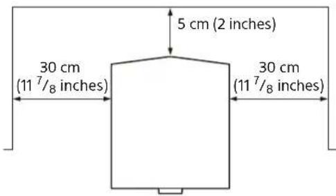
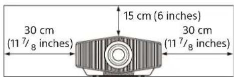
Note that the wall on the ventilation holes side may become hot.
Air from air conditioners or the ventilation holes of this unit or other devices may cause oscillation on the screen. Be sure not to install this unit in an area where the air from air conditioners or the ventilation holes of these devices reaches the front side of this unit.
Poorly ventilated location
Leave space of more than 30 cm (11 7/8 inches) around the unit.
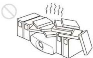
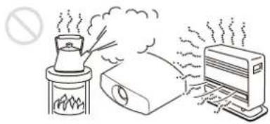
Hot and humid
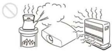
Locations subject to direct cool or warm air from an air-conditioner
Installing the unit in such a location may cause a malfunction of the unit due to moisture condensation or rise in temperature.
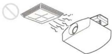
Near a heat or smoke sensor
Malfunction of the sensor may occur.

Very dusty and extremely smoky locations
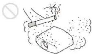
Unsuitable Conditions
Do not do any of the following while using the unit.
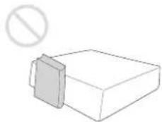
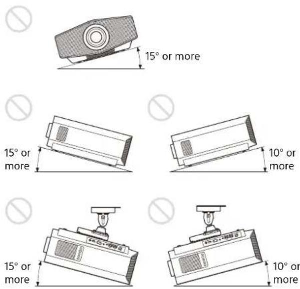
Tilting front/rear and left/right
Avoid using the unit tilted at an angle, as shown in the following illustrations.
Do not install the unit anywhere other than on a level surface or on the ceiling. Installing the unit in such a location may result in uneven color uniformity.
If the unit is tilted up or down, the image on the screen may be trapezoidal. Position the unit so that the lens is parallel to the screen.
When installing the unit at high altitudes
When using the unit in a location at an altitude of 1,000 m (approx. 3,280 feet) or higher, appropriately set "High Altitude Mode" in the Setup menu. Failing to do so could have adverse effects, such as reducing the reliability of certain components.
Safety precautions for installing the unit on a ceiling
- Never mount the projector on the ceiling or move it by yourself. Be sure to consult with qualified Sony personnel (charged).
- When installing the unit on a ceiling, be sure to use a safety wire, etc., to prevent the unit from falling. Entrust the installation to an experienced contractor or installer.
For dealers
Be sure to secure the cabinet cover firmly when installing to the ceiling firmly.
License Notice
Refer to "Notice on the Software" in the Help Guide and read the contents of the license.
Step 1
Preparing
Checking the Supplied Accessories
Check the carton to make sure it contains the following items:
Remote control RM-PJ24 (1)
Size AA (R6) batteries (2)
Lens cap (1)
When you purchase the projector, a lens cap is on the lens.
AC power cord (1) Setup Guide (this manual) (1)
Inserting the Batteries into the Remote Control
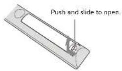
Insert the batteries II side first.
Removing the Lens Cap
Remove the lens cap before you use the projector.
Notes on the lens cap
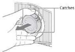
When removing the lens cap
When removing the lens cap, hold the parts other than the catches and pull it toward you. If you pull while holding the catches, the lens may be damaged.
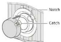
When attaching the lens cap
When attaching the lens cap, be sure to hook the catches of the lens cap on the notches of the lens to prevent it from falling out.
Step 2
Installing the Unit
1. Position the unit so that the lens is parallel to the screen.
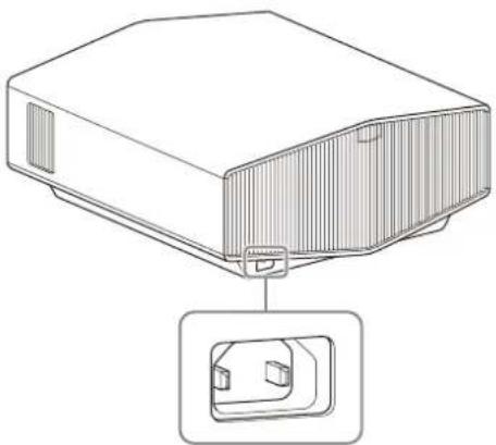
2. After connecting the AC power cord to the unit, plug the AC power cord into a wall outlet.
Rear of the unit
Front of the unit
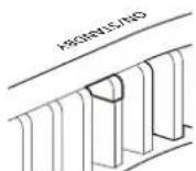
Lights in red.
Note
After connecting the AC power cord to the unit, the ON/STANDBY indicator may blink in orange.
You may not be able to control the unit while the indicator is blinking, but this is not a malfunction. Wait until it stops blinking and remains lit in red.
3. Press the I/⏻ (On/Standby) button to turn on the unit.
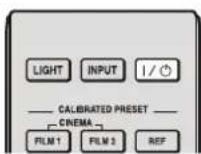
Front of the unit
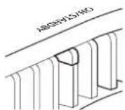
The ON/STANDBY indicator flashes in green, then it lights in green.
4. Project an image on the screen, then adjust the focus, size, and position.
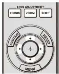
① Adjust the focus.
Press the LENS ADJUSTMENT (FOCUS) button to display the Lens Focus adjustment window (test pattern). Then adjust the focus of the picture by pressing the ↑/↓/←/→ button.
② Adjust the picture size.
Press the LENS ADJUSTMENT (ZOOM) button to display the Lens Zoom adjustment window (test pattern). Then adjust the size of the picture by pressing the ↑/↓/←/→ button.
③ Adjust the picture position.
Press the LENS ADJUSTMENT (SHIFT) button to display the Lens Shift adjustment window (test pattern). Then adjust to the proper position of the picture by pressing the ↑/↓/←/→ button.
Note
Do not touch the lens when you adjust the image position. Your fingers may be pinched when the lens extends/retracts.
To adjust the tilt of the installation surface
If the unit is installed on an uneven surface, use the front feet (adjustable) to keep the unit level.
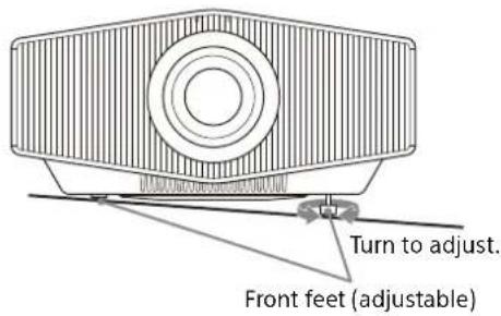
Notes
- Note that if the unit is tilted up or down, the projected image will be distorted in a trapezoidal shape.
- Be careful not to pinch your fingers when rotating the front feet (adjustable).
Lens adjustment window (test pattern)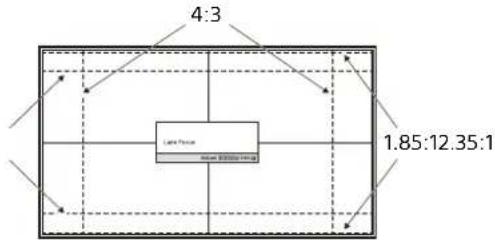
The dashed lines show the angle of view of each aspect ratio.
For more information, refer to "Installation and Connections" in the Help Guide.
Step 3
Connecting the Unit
When making connections, be sure to do the following:
- Turn off all devices before making any connections.
- Use the proper cables for each connection.
- Insert the cable plugs firmly; loose connections may reduce performance of picture signals or cause a malfunction. When unplugging a cable, be sure to grip the plug, not the cable itself.
- For more information, refer also to the instruction manual of the device to be connected.
![graph TD A["Right side of the unit"] --> B["to HDMI input"] B --> C["1 INPUT HDMI"] C --> D["2"] D --> E["3 to HDMI output"] E --> F["4 AV amplifier Speakers"] F --> G["5 Computer"] G --> H["6 to HDMI output"] H --> I["7 to HDMI output"] I --> J["HDMI cable (not supplied)"] style A fill:#f9f,stroke:…](/content/2026/03/573542/images/8266d9461a23b8e65edb22744304fcb3450e0fcbfe5a6911c97a7b2673404b35.jpg)
When you monitor and control the projector via the network, access the Setup page of the projector (refer to "Using Network Features" in the Help Guide) via a Web browser and enable the desired control protocol.
For more information, refer to "Installation and Connections" in the Help Guide.
Projecting the Picture
1 Turn on both the unit and the device connected to the unit. 2 Press INPUT to display the input palette on the screen. 3 Select the device from which you want to display images. Press INPUT repeatedly or press ↑/↓/⊕ (enter) to select the device from which to project.
Turning Off the Power
1 Press the I/⏻ (On/Standby) button. The message "POWER OFF?" appears. 2 Press the I/⏻ (On/Standby) button again before the message disappears. The ON/STANDBY indicator flashes in green and the fan continues to run to reduce the internal heat.
The fan stops and the ON/STANDBY indicator changes from flashing green to remaining red.
The power is turned off completely, and you can disconnect the AC power cord.
Note
Never disconnect the AC power cord while the indicator is flashing.
Tip
You can turn off the unit by holding the I/⏻ (On/Standby) button for about 1 second, instead of performing the above steps.
Selecting the Picture Viewing Mode
Press one of the CALIBRATED PRESET buttons.
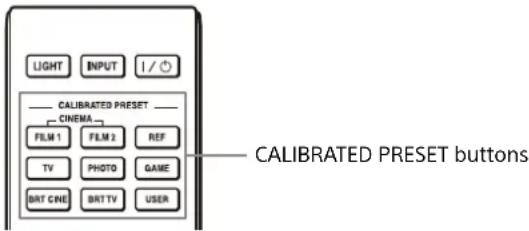
| Setting items Description | |
| CINEMA FILM 1(Cinema Film 1) | Image quality suited for reproducing the wide dynamic and clear images typical of master positive film. |
| CINEMA FILM 2(Cinema Film 2) | Image quality suited for reproducing the rich tone and color typical of a movie theater, based on “Cinema Film 1.” |
| REF (Reference) | Image quality suited for reproducing the original image quality faithfully, or to enjoy the image quality without any adjustment. |
| TV (TV) | Image quality suited for watching TV programs, sports, concerts, and other video images. |
| PHOTO (Photo) | Image quality suited for viewing still images taken with a digital camera and other devices. |
| GAME (Game) | Image quality suited for gaming, with well-modulated colors and fast response. |
| BRT CINE(Bright Cinema) | Image quality suited for watching movies in a bright room. |
| BRT TV(Bright TV) | Image quality suited for watching TV programs, sports, concerts, and other video images in a bright room. |
| USER (User) | You can set and adjust the image quality to suit your taste, then you can save the setting. The default setting is the same as “Reference.” |
| IMAX Enhanced Image quality suited for watching IMAX Enhanced contents.Press the MENU button and select from “Calib. Preset” in the Picture menu. | |
For more information, refer to "Projecting" in the Help Guide.
About Indicators
The ON/STANDBY or WARNING indicator lights up or flashes if there is any trouble with your projector. If there is any problem or an error message appears on the screen, refer to "Error Handling" in the Help Guide.
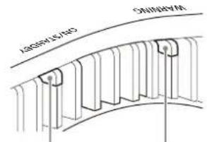
ON/STANDBY indicator WARNING indicator
| Flashing/Lighting indicators The number of flashes | Cause and Remedy |
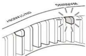 (Flashes in red)(L) (Flashes in red)(L) | Three times The unit does not light properly due to an abnormality of the light source and light source power. Turn off, then turn on the power after a while.If the symptom persists, consult withqualified Sony personnel. |
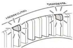 (Flashes in red) (Flashes in red)Both indicators flash (Flashes in red) (Flashes in red)Both indicators flash | Twice The internal temperature is unusually high. Check to ensure that nothing is blocking the ventilation holes and the unit is not being used at high altitudes. |
| Three times The fan is broken. Consult with qualified Sony personnel. |
Note
If the symptom persists even after carrying out the above methods, consult with qualified Sony personnel. If the indicator starts flashing in a way other than the above, turn off, and then turn on the power with the I/⏻ (On/Standby) button on the remote control or control panel of the unit. If the symptom is shown again, consult with qualified Sony personnel.
If there is any problem or an error message appears on the screen, refer to "Error Handling" in the Help Guide.
Dimensions
Front
Unit: mm (inches)
Bottom Unit: mm (inches)
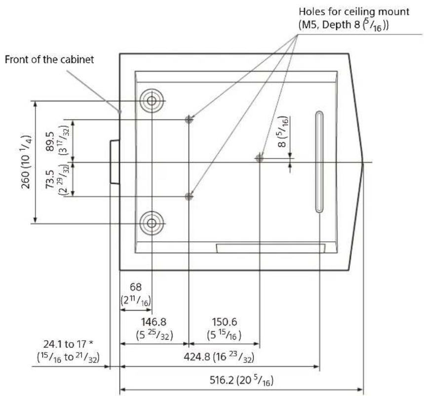
* Varies depending on how focus is adjusted.
Note
Holes for the ceiling mount
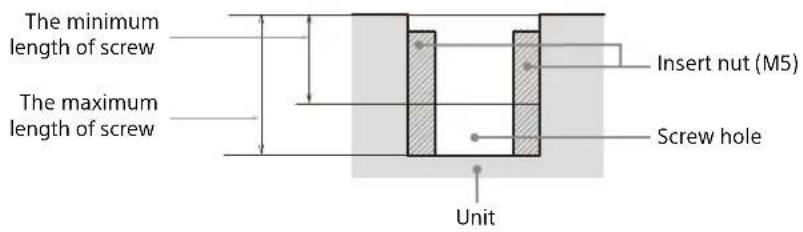
Use the screws with a length of 6.4 mm (1/4 inches, minimum) to 8.0 mm (1/16 inches, maximum) for the ceiling mount. Recommended tightening torque (tension when turning a screw towards the direction of rotation): 1.4 ± 0.2 N-m
Minimum zoom: α = 25.5°

Front of the device
Lights up in red.
Note
ON/STANDBY indicator WARNING indicator
Minimum zoom: α = 25.5°
https://rd1.sony.net/help/vpl/xw5000/it/
Italian
Minimum zoom: α = 25.5°

Hot and humid
WARNING light ON/STANDBY light



- ABOUT THIS MANUAL
- STEP
- MANUALS SUPPLIED
- SETUP GUIDE (THIS DOCUMENT)
- HELP GUIDE (WEB OPERATING INSTRUCTIONS)
- ENGLISH
- WARNING
- CAUTION
- IMPORTANT
- FOR CUSTOMERS IN NORWAY
- LOCATION INFORMATION OF THE LABELS
- LIGHT SOURCE SPECIFICATIONS
- BEAM DIVERGENCE ANGLE FROM LENS OF THIS UNIT
- FOR THE CUSTOMERS IN THE U.S.A
- FOR THE CUSTOMERS IN CANADA
- FOR THE CUSTOMERS IN EUROPE
- FOR THE CUSTOMERS IN KOREA
- PRECAUTIONS
- ON SAFETY
- ON PREVENTING INTERNAL HEAT BUILD-UP
- ON REPACKING
- ON WATCHING 3D VIDEO IMAGES
- SAFETY PRECAUTIONS
- ON INSPECTION OF LIGHT SOURCE RELATED PARTS
- NOTE ON LEAVING UNUSED FOR LONG PERIODS
- ON LCD PROJECTOR
- ON CONDENSATION
- NOTES ON SECURITY
- DO NOT PLACE THIS PRODUCT CLOSE TO MEDICAL DEVICES
- NOTES ON INSTALLATION AND USAGE
- UNSUITABLE INSTALLATION
- NEAR WALLS
- POORLY VENTILATED LOCATION
- LOCATIONS SUBJECT TO DIRECT COOL OR WARM AIR FROM AN AIR-CONDITIONER
- NEAR A HEAT OR SMOKE SENSOR
- VERY DUSTY AND EXTREMELY SMOKY LOCATIONS
- UNSUITABLE CONDITIONS
- TILTING FRONT/REAR AND LEFT/RIGHT
- WHEN INSTALLING THE UNIT AT HIGH ALTITUDES
- SAFETY PRECAUTIONS FOR INSTALLING THE UNIT ON A CEILING
- FOR DEALERS
- LICENSE NOTICE
- PREPARING
- CHECKING THE SUPPLIED ACCESSORIES
- INSERTING THE BATTERIES INTO THE REMOTE CONTROL
- REMOVING THE LENS CAP
- NOTES ON THE LENS CAP
- WHEN REMOVING THE LENS CAP
- WHEN ATTACHING THE LENS CAP
- INSTALLING THE UNIT
- NOTE
- TO ADJUST THE TILT OF THE INSTALLATION SURFACE
- NOTES
- CONNECTING THE UNIT
- WHEN MAKING CONNECTIONS, BE SURE TO DO THE FOLLOWING
- PROJECTING THE PICTURE
- TURNING OFF THE POWER
- TIP
- SELECTING THE PICTURE VIEWING MODE
- ABOUT INDICATORS
- DIMENSIONS
- HOLES FOR THE CEILING MOUNT
- ITALIAN
- HOT AND HUMID
Brand : SONY
Model : VPLXW7000
Category : Projector