
ZISTE3000IV - Generator Zipper - Free user manual and instructions
Find the device manual for free ZISTE3000IV Zipper in PDF.
| Brand | Zipper |
| Model | ZISTE3000IV |
| Category | Generator |
| Engine type | 4-stroke gasoline engine |
| Fuel | Unleaded gasoline |
| Recommended engine oil | 15W40 |
| AC output voltage | 230 V |
| DC output voltage | 12 V |
| Frequency | 50 Hz |
| Maximum power | 3 000 W |
| Rated power | 2 700 W |
| Starting | Recoil starter |
| ECO mode | Yes, fuel consumption reduction |
| Overload protection | Yes, indicator light and shutdown |
| Low oil protection | Yes, automatic shutdown |
| Grounding | Ground screw |
| Telescopic handle | Yes, adjustable |
| Warranty | 2 years (non-professional use), 1 year (professional) |
Frequently Asked Questions - ZISTE3000IV Zipper
User questions about ZISTE3000IV Zipper
0 question about this device. Answer the ones you know or ask your own.
Ask a new question about this device
Download the instructions for your Generator in PDF format for free! Find your manual ZISTE3000IV - Zipper and take your electronic device back in hand. On this page are published all the documents necessary for the use of your device. ZISTE3000IV by Zipper.
USER MANUAL ZISTE3000IV Zipper
natural_image
White and black ZIPPER water purifier with green and yellow branding (no visible text or symbols on body)ZI-STE3000IV
EAN: 9120039232607


Engine don't start with low oil!!
YOUR
JOB.
OUR
TOOLS.
1 INHALT / INDEX
1 INHALT/INDEX....2
2 SICHERHEITSZEICHEN / SAFETY SIGNS / SEÑALES DE SEGURIDAD / SYMBOLES
DE SÉCURITÉ / VARNOSTNI ZNAKI / SIGURNOSNI ZNAKOVI 6
11.1 Intended use of the machine 27
11.1.1 Technical restrictions....27
11.1.2 Prohibited applications / Dangerous misuse....27
11.2 User Requirements....27
11.3 General safety instructions....28
11.4 Electrical safety 28
11.5 Special safety instructions for this machine 28
11.6 Safety instructions for machines with combustion engine....29
11.7 Hazard warnings 29
11.7.1 Residual risks....29
11.7.2 Hazardous situations....30
12 TRANSPORT 30
13 OPERATION....30
13.1 Preparation....30
13.1.1 Checking delivery content....30
13.12 Requirements for the installation site 31
13.2 Pre-operation check....31
13.2.1 Check engine oil level 31
13.2.2 Check fuel tank level 31
13.2.3 Grounding 31
13.3 Information on Initial Start-up 31
13.3.1 Test Run Initial Start-up 31
13.4 Switching on the machine by an electrical amateur 32
13.5 Operating instructions....32
13.5.1 Operation of the machine to over 1500m above sea level....32
13.5.2 Connecting devices 32
13.6 Operation 32
13.6.1 Switch the engine/machine on 32
13.6.2 Switch the machine off 33
13.6.3 ECO-mode 33
13.6.4 Teleskope handle 33
13.8 DC Operation....34
14 CLEANING, MAINTENANCE, STORAGE, DISPOSAL....34
14.1 Cleaning 34
14.2 Maintenance 35
14.2.1 Maintenance plan 35
14.22 Engine oil change 35
14.23 Air filter 36
14.2.4 Spark plug 37
14.3 Storage....37
14.4 Disposal 37
15 TRÓUBLESHOOTING 38
16 PRÓLOGO (ES)....39
17 SEGURIDAD......40
22 AVANT-PROPOS (FR)....53
23 SECURITE 54
26.4 Elimination....65
27 RESOLUTION DE PANNE 65
28 PREDGOVOR (SL) 67
29 VARNOST....68
29.1 Uporaba za predvideni namen....68
31 UPORABA STROJA 72
31.1 Pripravljalna dela....72
31.1.1 Preverjačje obsega dobave....72
EN CE-Conformal! - This product complies with the EC-directives.
EN READ THE MANUAL! Read the user and maintenance carefully and get familiar with the controls in order to use the machine correctly and to avoid injuries and machine defects.
EN ATTENTION! Ignoring the safety signs and warnings applied on the machine as well as ignoring the security and operating instructions can cause serious injuries and even lead to death.
EN Danger of Intoxication (CO)! Only use outdoors and far from open windows and vents!
EN Warning of flammable liquids; turn off the engine before filling (gasoline)
EN ATTENTION! For transport, oil has been drained. Fill up with 4-stroke quality motor oil before first operation! Failure to do so will result in permanent engine damage and void guarantee.
EN Missing or non-readable security stickers have to be replaced immediately.
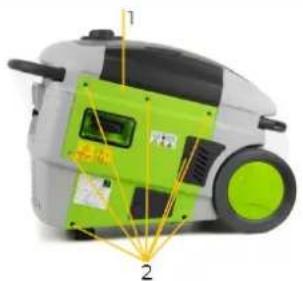
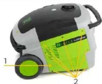
| Beschreibung / Description | |
| 1 | Stromerzeuger / generator / Generador / Groupe électrogène / Električni generator / Električni generator |
| 2 | DC-Kabel / DC-cable / Cable-CC / Câble DC / Kabel za enosmerno napetost / DC kabel |
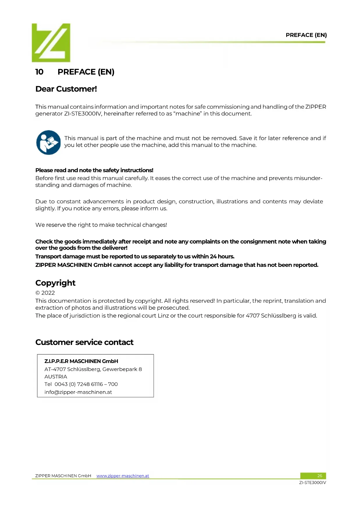
| 3 | Öleinfüllkanne / oil filler / Bidón de llenado de aceite / Bidon de remplissage d'huile / Posoda za nalivanje olja / Kantica za punjenje ulja |
| 4 | Betriebsanleitung / user manual / Instrucciones de servicio / Mode d'emploi / Navodila za uporabo / Upute za uporabu |
| 5 | 230 V Stecker (Reserve) / 230 V plug (reserve) / Conector 230 V (reserva) / Fiche 230 V (réserve) / Vtič 230 V (rezerva) / Utikač od 230 V (rezerva) |
| 6 | Zündkerzenschlüssel / spark plug key / Llave para bujía / Clé de bougie d'allumage / Ključ za svečke / Ključ za svjećice |
NOTE: Engine oil and fuel not included in the delivery content
1: Betrieb / running / Funcionamiento / Fonctionnement / Uporaba stroja / Rad
2: Überlastungskontrollleuchte / overload alarm / Piloto de control de sobrecarga / Voyant de contrôle de la surcharge / Kontrolna lučka za preobremenitev / Lampica indikatora preopterećenja
3: Öl-Mindermengenanzeige / low oil alarm / Indicador de cantidad mínima de aceite / Affichage de la quantité minimale d'huile / Prikaz minimalnega nivoja olja / Lampica za nizak nivo ulja
3.3 Technische Daten / Technical data / Datos técnicos / Données techniques / Tehnični podatki / Tehnički podaci
(DE) Hinweis Geräuschangaben: Die angegebenen Werte sind Emissionswerte und müssen damit nicht zugleich auch sichere Arbeitsplatzwerte darstellen. Obwohl es eine Korrelation zwischen Emissions- und Immissionspegeln gibt, kann daraus nicht zuverlässig abgeleitet werden, ob zusätzliche Vorsichtsmaßnahmen notwendig sind oder nicht. Faktoren, welche den am Arbeitsplatz tatsächlich vorhandenen Immissionspegel beeinflussen, beinhalten die Eigenart des Arbeitsraumes und andere Geräuschquellen, d. h. die Zahl der Maschinen und anderer benachbarter Arbeitsvorgänge. Die zulässigen Arbeitsplatzwerte können ebenso von Land zu Land variieren. Diese Information soll jedoch den Anwender befähigen, eine bessere Abschätzung von Gefährdung und Risiko vorzunehmen.
(EN) Notice noise emission: The values given are emission values and therefore do not have to represent safe workplace values at the same time. Although there is a correlation between emission and immission levels, it cannot be reliably deduced whether additional precautions are necessary or not. Factors influencing the actual immission level at the workplace include the nature of the workspace and other noise sources, i.e. the number of machines and other adjacent operations. The permissible workplace values may also vary from country to country. However, this information should enable the user to make a better assessment of hazard and risk.
(ES) Aviso sobre los valores de ruido: Los valores indicados son valores de emisión y, por lo tanto, no representan necesariamente al mismo tiempo valores seguros en el lugar de trabajo. Aunque hay una correlación entre los niveles de emisión y los de inmisión, no se puede deducir con certeza si es necesario adoptar medidas de precaución adicionales o no. Entre los factores que influyen en el nivel de inmisión real en el lugar de trabajo, se encuentran la naturaleza del espacio de trabajo y otras fuentes de ruido, es decir, el número de máquinas y otros procesos de trabajo adyacentes. Asimismo, los valores admisibles en el lugar de trabajo pueden variar de un país a otro. No obstante, esta información debe capacitar al usuario a evaluar mejor los peligros y los riesgos.
(FR) Avis Données sur le bruit : Les valeurs indiquées sont des valeurs d'émission et ne représentent donc pas nécessairement des valeurs de sécurité sur le lieu de travail. Bien qu'il existe une corrélation entre les niveaux d'émission et d'immission, il est impossible de déduire de manière fiable si des mesures de précaution supplémentaires sont nécessaires ou non. Les facteurs influençant le niveau d'immission réellement présent sur le lieu de travail comprennent les caractéristiques de la salle de travail et d'autres sources de bruit, c'est-à-dire le nombre de machines et d'autres processus de travail adjacents. Les valeurs autorisées sur le lieu de travail peuvent également varier d'un pays à l'autre. Toutefois, ces informations devraient permettre à l'utilisateur de mieux évaluer le danger et le risque.
(SL) Opomba glede podatkov o hrupu: Navedene vrednosti so emisijske vrednosti in ne predstavljajo obenem vrednosti za varno delovno mesto. Ker ne obstaja korelacija med emisijskimi in imisijskimi ravnmi, se iz tega ne da zanesljivo izpeljati, ali so potrebni dodatni varnostni ukrepi ali ne. Faktorji, ki lahko v trenutni situaciji vplivajo na raven imisij, so posebne lastnosti prostora, drugi viri hrupa, na primer število strojev in drugi sosednji delovni procesi. Dopustne vrednosti na delovnih mestih lahko med posameznimi državami variirajo. Ta informacija pa kljub temu uporabniku omogoča izdelati boljšo oceno nevarnosti in tveganj.
(HR) Obavijest o emisiji buke: Navedene vrijednosti su vrijednosti emisije i stoga ne moraju istovremeno predstavljati vrijednosti sigurnog radnog mjesta. Iako postoji korelacija između razine emisije i imisije, ne može se pouzdano zaključiti jesu li potrebne dodatne mjere opreza ili ne. Čimbenici koji utječu na stvarnu razinu imisije na radnom mjestu uključuju prirodu radnog prostora i druge izvore buke, tj. broj strojeva i drugih susjednih radnih procesa. Također, dopuštene vrijednosti na radnom mjestu se mogu razlikovati od zemlje do zemlje. Međutim, te bi informacije trebale omogućiti korisniku bolju procjenu opasnosti i mogućih rizika.
| Spezifikation / Specification | |
| Motortyp / engine type / Tipo de motor / Type de moteur / Tip motorja / Tip motora | 1-Zylinder 4-Takt170F |
| Hubraum / displacement / Cilindrada / Cylindrée / Delovna prostornina / Zapremina | 207 cm3 |
| Motorleistung / engine power / Potencia del motor / Puissance du moteur / Moč motorja / Snaga motora | 4,3 kW |
| Motordrehzahl / engine speed / Régimen de revoluciones del motor / Vitesse de rotation du moteur / Število vrtljajev motorja / Broj okretaja motora | max. 3600 min-1 |
| Starter / starter / Arrancador / Démarreur / Zaganjalnik / Starter | Seilzug / recoil |
| Zündung / ignition / Arranque / Allumage / Vžig / Paljenje | CDI |
| Zündkerze / spark plug / Bujía / Bougie d'allumage / Svečke / Svjećica | F6RTC |
| empfohlenes Motoröl / recommended engine oil / Aceite para motor recomendado / Huile moteur recommandée / Priporočeno motorno olje / Preporučeno motorno ulje | 15W40 (10W40, SAE30) |
| Motoröltankkapazität / oil tank capacity / Capacidad del cárter / Capacité du réservoir du moteur / Prostornina rezervoarja za motorno olje / Kapacitet spremnika motornog ulja | 520 ml |
| Kraftstoff / fuel type / Carburante / Carburant / Gorivo / Gorivo | ROZ95 / RON 95 (E5) |
| Tank-Kapazität / fuel tank capacity / Capacidad del depósito / Capacité du réservoir / Prostornina posode za gorivo / Kapacitet spremnika goriva | 10 l |
| max. Leistung / max. performance / Potencia máx. / Puis-sance max. / maks. Moč / maks. jačina | 3,2 kW (S2 5min) |
| Generatordauerleistung / rated output power / Potencia del generador / Puissance du générateur / Trajna moč generatorja / Snaga generatora | 2,8 kW (COP) |
| Laufleistung bei Generatordauerleistung / operation time rated output power generator / Kilometraje con potencia del generador / Performance avec puissance du générateur / Trajna moč generatorja / Radna izvedba pri kontinuiranoj snazi generatora | 6 h |
| Nennstrom / rated current / Corriente nominal / Courant nominal / Nazivni tok / Nazivna struja | 12,2 A |
| Nennleistungsfaktor /rated power factor / Factor de potencia nominal / Facteur de puissance nominale / Nazivni faktor moči / Nazivni faktor snage | 1,0 |
| AC-Steckdose / AC-socket / Enchufe-AC / Prise CA / Vtičnica za izmenično napetost / AC utičnica | 2 x 230 V / 50 Hz |
| Gleichstromausgang / direct current output (DC) / Salida de corriente continua / Sortie de courant continu / Izhodni enosmerni tok / Izlaz istosmjerne struje (DC) | 12 V max. 6A |
| Leistungsklasse / performace class / Clase de rendimiento / Classe de puissance / Razred zmogljivosti / Klasa performansi | G2 |
| Qualitätsklasse / quality class / Clase de calidad / Classe de qualité / Kakovostni razred / Klasa kvalitete | A |
| Schutzart / IP-rating / Grado de protección / Classe / Vrsta zaščite / Vrsta zaštite | IP23M |
| Garantierter Schall-Leistungspegel / guaranteed sound power level LWA / Nivel de potencia acústica garantizado / Seuil de pression acoustique garanti / Zagotovljena raven zvočne moči / Garantirana razina snage zvuka | 96 dB(A) |
| Schall-Druckpegel / sound pressure level LPA / Nivel de presión sonora / Niveau de pression acoustique / Raven zvočnega tlaka / Razina buke | 64-76 dB(A) / 7 m |
| Gewicht (Netto) / weight (net) / Peso (neto) / Poids (net) / Masa (neto) / Težina (neto) | 39,3 kg |
| Gewicht (Brutto) / weight (gross) / Peso (bruto) / Poids (brute) / Masa (bruto) / Težina (bruto) | 44,3 kg |
| Maschinenmaße (LxBxH) / machine dimension (LxWxH) / Dimensiones de la máquina (LxAxH) / Dimensions de la machine (LxlxH) / Mere stroja (DxŠxV) / Dimenzije stroja (DxŠxV) | 700 x 440 x 515 mm |
4 VORWORT (DE)
natural_image
Close-up of a green and gray robotic vacuum cleaner with labeled parts (1 and 2), no visible text or symbols on the device itself.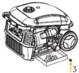
natural_image
Technical line drawing of a mechanical device with gears and housing (no text or symbols)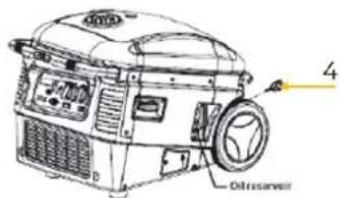

natural_image
Illustration of a green and black vacuum cleaner with labeled parts (1 and 2), no text or symbols present.

This manual contains information and important notes for safe commissioning and handling of the ZIPPER generator ZI-STE3000IV, hereinafter referred to as “machine” in this document.

This manual is part of the machine and must not be removed. Save it for later reference and if you let other people use the machine, add this manual to the machine.
Please read and note the safety instructions!
Before first use read this manual carefully. It eases the correct use of the machine and prevents misunderstanding and damages of machine.
Due to constant advancements in product design, construction, illustrations and contents may deviate slightly. If you notice any errors, please inform us.
We reserve the right to make technical changes!
Check the goods immediately after receipt and note any complaints on the consignment note when taking over the goods from the deliverer!
Transport damage must be reported to us separately to us within 24 hours.
ZIPPER MASCHINEN GmbH cannot accept any liability for transport damage that has not been reported.
Copyright
© 2022
This documentation is protected by copyright. All rights reserved! In particular, the reprint, translation and extraction of photos and illustrations will be prosecuted.
The place of jurisdiction is the regional court Linz or the court responsible for 4707 Schlüsslberg is valid.
Customer service contact
This section contains information and important notes on the safe commissioning and handling of the machine.

For your safety, read this manual carefully before commissioning. This will enable you to handle the machine safely and thus prevent misunderstandings as well as personal injury and damage to property. Pay special attention to the symbols and pictograms used on the machine as well as the safety information and danger warnings!
11.1 Intended use of the machine
The machine is intended exclusively for the following activities:
This machine is designed exclusively for operating electric devices whose max. performance is within the specifications for the machine and the suitability according to the respective manufacturer's specifications of the device to be operated is ensured. A higher starting current of inductive loads must be considered.
NOTE

ZIPPER MASCHINEN assumes no responsibility or warranty for any other use or use beyond this and for any resulting damage to property or injury.
II.1.1 Technical restrictions
The machine is designed for the work under the following conditions:
Relative humidity: max. 70 %
Temperature (for operation): +5°C to +40°C
Temperature (Storage, Transport): -20° C to +55° C
Max. altitude above sea level 1500m
11.12 Prohibited applications / Dangerous misuse
- Operating the machine without adequate physical and mental fitness.
- Operating the machine without knowledge of the manual.
- Modifying the machine design.
- Operating the machine in wet and rainy conditions.
- Operating the machine with wet hands.
- Operating the machine in a potentially explosive environment.
- Do not smoke nearby the machine while the machine is in operation.
- Operating the machine indoors or in closed areas.
• Never connect the machine to the power supply (socket-outlet)!
• Never connect the machine with other energy sources (generators)! - Operating the machine outside the technical limits specified in this manual.
- Removing of the safety markings attached to the machine.
- Modifying, circumventing or disabling the safety devices of the machine.
• Never leave the machine unattended, especially when children are around!
The non-intended use or the disregard of the explanations and instructions described in this manual will result in the expiration of all warranty claims and compensation claims for damages against ZIPPER MASCHINEN GmbH.
11.2 User Requirements
The machine is designed to be operated by one person. The prerequisites for operating the machine are physical and mental fitness as well as knowledge and understanding of the operating instructions. Persons who, due to their physical, sensory or mental capabilities, inexperience or lack of knowledge, are unable to operate the machine safely must not use the machine without supervision or instruction by a responsible person.
Please note that locally applicable laws and regulations determine the minimum age of the operator and may restrict the use of this machine!
Work on electrical components or equipment may only be carried out by a qualified electrician or under the guidance and supervision of a qualified electrician.
Observe local regulations for electrical safety.
Put on your personal protective equipment before working on the machine.
11.3 General safety instructions
To avoid malfunctions, damage and health impairments when working with the machine, the following points must be observed in addition to the general rules for safe working:
- Check the machine for completeness and function before starting. Only use the machine if the separating and other non-separating protective devices required for machining have are fitted.
• Make sure that the guards are in good working order and properly maintained. - Select a level, vibration-free surface as the installation area.
- Ensure sufficient space around the machine!
- Ensure sufficient lighting conditions at the workplace to avoid stroboscopic effects.
- Ensure a clean working environment.
- Keep the area around the machine free of obstacles.
- Remove tool keys and other setting tools before switching on the machine.
- Never leave the running machine unattended. Switch off the machine before leaving the working area and secure it against unintentional or unauthorized restarting.
- The machine may only be operated, maintained or repaired by persons who are familiar and who have been informed about the dangers arising from this work.
- Ensure that unauthorized persons keep a safety distance from the machine and keep children away from the machine.
• Always work with care and the necessary caution and never use excessive force.
- Do not overload the machine!
- Wear suitable protective equipment (ear protection)!
• Never wear loose jewellery, loose clothing or accessories (e.g. tie, scarf).
- Do not work on the machine if you are tired, not concentrated or under the influence of medication, alcohol or drugs!
- Do not use the machine in areas where vapours of paints, solvents or flammable liquids represent a potential danger (danger of fire or explosion!).
- Shut down the machine and disconnect it from the power supply, before adjustment, change-over, cleaning, maintenance or repair work, etc. Before starting work on the machine, wait until all tools or machine parts have come to a complete standstill and secure the machine against unintentional restart.
- Warning signs and/or stickers on the machine that are illegible or have been removed must be replaced immediately!
11.4 Electrical safety
- Before commissioning, the machine and its electrical equipment (including power cable and plug) should be checked to ensure that there is no defect.
- Only use suitable extension cables. When using extension cables or mobile distribution networks, ensure that the resistance value does not exceed 1.5 Ω. As a guideline, the total length of the cables should not exceed 60 m for a cross-section of 1.5 mm 2 and 100 m for a cross-section of 2.5 mm 2 .
- Considering the high mechanical forces, only durable rubber cables (IEC 245) or equivalent equipment should be used.
- A damaged or tangled cable increases the risk of electric shock. Handle the cable with care. Never use the cable to carry, pull or disconnect the power tool. Keep the cable away from heat, oil, sharp edges or moving parts.
• Use the machine only when the ON-OFF switch is in good working order.
11.5 Special safety instructions for this machine
- Do not use the machine if it is raining, wet or has high humidity. RISK OF ELECTRIC SHOCK. DANGER OF LIFE!
- Only operate the machine outdoors. Always ensure adequate ventilation and heat dissipation in the operating area.
- Place the machine at least 1m away from buildings and the equipment connected to it.
- Place the machine in a secure, level position. Do not turn, tip or change the machines position while it is working.
- Never connect the machine directly to another power supply network (e.g. the mains power supply, other power generators,...).
11.6 Safety instructions for machines with combustion engine
• Never change the motor and machine settings.
- The machine is to be operated only with equipment whose voltage specifications conform to the machine's output voltage.
- The machine is equipped with a low oil alarm. If oil level is low, it is not possible to restart the engine.
- Danger of burns! During the operation flow of hot exhaust gases and engine parts such as the muffler and engine become hot.
• After the operation, the machine must cool down. Otherwise there is an imminent risk of burns.
- Never place a hot machine in dry grass or other easily flammable materials.
- Never cover the running machine.
- Always keep the area around the muffler free of foreign substances such as leaves, paper, cardboard, etc. A hot muffler could ignite these substances and cause a fire.
- Do not touch the spark plug connector when the engine is running (electric shock!).
• WARNING: Gasoline is highly flammable!
- Stop the engine before refuelling.
• Smoking and open flames are prohibited during refuelling.
- Do not open the fuel filler cap while the appliance is running or hot. Fuel and escaping fuel vapours can ignite on hot parts of the unit.
- Do not refuel when the engine and carburettor are still very hot.
• Refuel only outdoors or in a well ventilated area.
- Avoid contact with skin and clothes (fire hazard).
- Check after refuelling fuel filler cap and check for leaks.
- Start the engine at least 3 meters from the tank location.
• Spilled fuel is wiped up immediately.
- Make sure the fuel does not overflow. If the fuel overflows, the engine must not be started. Remove any dirt from the appliance and prevent any attempt at ignition until fuel fumes have evaporated.
• Damaged fuel tank or other fuel filler cap must be replaced immediately.
- Check the fuel line and tank regularly for leaks and cracks. Do not operate the machine if there are known leaks in the fuel system.
• After the operation, the fuel tap must be closed.
- Keep the fuel in suitable containers only.
• Danger of Intoxication! Only use outdoors and far from open windows and vents!
- Exhaust fumes contain toxic carbon monoxide. The exposure can cause unconsciousness and death.
• No other person, children or pets shall remain within 5m!
11.7 Hazard warnings
11.7.1 Residual risks
Despite intended use, certain residual risk factors remain.
- Risk of burns:
Touching the mufflers, exhaust and other machine components which can be hot after prolonged continuous operation or when the engine is hot cause severe burns.
• Risk of fire and explosion:
Gasoline is highly flammable and explosive under certain conditions.
NEVER refuel fuel or engine oil while the machine is in operation or is hot.
When refuelling at places where fuel is stored do not smoke or allow open flames or sparks.
Do not overfill the fuel tank and avoid the spillage of gasoline during refuelling. If fuel is spilled make sure the area is completely dry and cleaned before starting the engine.
Make sure that the fuel filler cap is tightly closed again after refuelling safely.
- Chemical risks
Never use or refuel a gasoline or diesel engine in a closed area without adequate ventilation.
Carbon monoxide emissions from the internal drive units of the engine can cause in confined spaces through inhalation health effects and death. Therefore use the machine only in well-ventilated rooms or outdoors in operation.
Liquid fuels can cause serious damage on the skin and the environment.
- Risk of electric shock
Direct electrical contact may cause electric shock.
Never touch the unit with wet hands. Provide adequate grounding.
- Hearing damage
A longer stay in the immediate vicinity of the running unit may cause hearing damage.
Wear ear protectors!
T1.72 Hazardous situations
Due to the structure and construction of the machine, hazardous situations may occur which are identified in these operating instructions as follows:
DANGER

A safety instruction designed in this way indicates an imminently hazardous situation which, if not avoided, will result in death or serious injury.
WARNING

Such a safety instruction indicates a potentially hazardous situation which, if not avoided, may result in serious injury or even death.
CAUTION

A safety instruction designed in this way indicates a potentially hazardous situation which, if not avoided, may result in minor or moderate injury.
NOTE

A safety note designed in this way indicates a potentially dangerous situation which, if not avoided, may result in property damage.
Regardless of all safety regulations, your common sense and your appropriate technical aptitude/training are and remain the most important safety factor in the error-free operation of the machine. Safe working depends on you!
12 TRANSPORT
• Always switch off the engine when transporting and refuelling the machine!
- Ensure that the fuel tap and the ON-OFF switch are turned to position "OFF".
• After operation, allow the machine to cool down for at least 15 minutes.
Transport of the machine in a vehicle:
- Check that no fuel can leak from the tank. Ensure that the fuel filler cap is tightly closed.
- When transporting the machine in a vehicle, ensure that the machine is appropriately secured! The machine must be carried and transported in an upright position to avoid oil or fuel leakage.
- If the machine is in a vehicle, do not start the engine. Take the machine out of the vehicle and run it outdoors only.
- Protect the machine from excessive heat during transport. If the machine remains in a closed vehicle for a long time, the fuel may ignite due to overheating.
13 OPERATION
Only operate the machine when it is in perfect condition. Before each operation, a visual inspection of the machine must be carried out.
13.1 Preparation
13.1.1 Checking delivery content
Check the delivery immediately for transport damage and missing parts. Report any damage or missing parts to your dealer or the shipping company immediately. Visible transport damage must also be noted immediately on the delivery note in accordance with the provisions of the warranty, otherwise the goods are deemed to have been properly accepted.
13.12 Requirements for the installation site
Place the machine on a level, solid surface to prevent the machine from tipping over.
When dimensioning the required space, take into account that the operation must be possible without restrictions at all times.
13.2 Pre-operation check
13.2.1 Check engine oil level
NOTE

The machine is delivered without engine oil and fuel! Engine oil 15W40 must be filled before first use!

NOTE

A too low oil level will damage the engine and shorten the life of the machine. Therefore, check the engine oil level before every start and top up the engine oil if necessary.
NOTE: Engine does not start with low oil (low oil alarm lights up).
See capture maintenance => engine oil change.
132.2 Check fuel tank level
NOTE

Observe the safety regulations for fuel control. Filter the fuel during refuelling to prevent foreign particles from entering the combustion chamber. Wipe up leaked fuel.
WARNING

Never refuel if the engine is running

- Place the machine on a firm and flat surface.
- Open the fuel filler cap (1).
- Check the fuel filter (2).
NOTE: Never refuel without fuel filter!
- Refuel with unleaded gasoline, until the max. filling level (F=full) is reached.
- Close the fuel filler cap (1) tightly after refuelling.
B23 Grounding
The machine is designed with the protective measure protective separation with potential equalization in the IT network. A grounding by means of a grounding screw and a grounding spike is thus designed to discharge static charges. For this purpose, connect the grounding screw of the power generator to a grounding spike (grounding cable cross-section 16mm 2 ). If other protective measures are required, clarify them with a qualified electrician and have them documented in order to check their effectiveness..
13.3 Information on Initial Start-up
13.3.1 Test Run Initial Start-up
Make sure to treat the machine with care, when using it for the first time.
- Let the machine run idle for about 3 minutes before connecting the generator with consumer load.
- Pay attention to abnormal noises.
• Pay attention to the exhaust fumes (too black, too white)?
If these points meet the demands, the machine can be used further. Otherwise stop the machine and find the cause of the problem.
13.4 Switching on the machine by an electrical amateur
Switching on without a qualified electrician, the following requirements must be met:
- The machine is checked at regular intervals by a qualified electrician (recommended every six months).
- Extension and connection cables as a well as plugs/sockets must be checked regularly for mechanical damage.
• Only use cables and conductors that are permanently suitable for the intended use.
13.5 Operating instructions
NOTE

- Always place the machine on a firm and flat surface! No turning, tilting or moving during the engine is running.
• Always check oil and fuel level before starting. - Do not connect the device before the machine is running at full speed. Disconnect the device before turning the machine off.
- Connected devices must be in perfect condition.
- Keep the cable length to the device as short as possible.
NOTE: For a period of 5 minutes, the machine is designed to provide maximum performance. For continuous operation, the specified rated performance should not be exceeded.
13.5.1 Operation of the machine to over 1500m above sea level
- When operating at high altitudes, the air/fuel mixture becomes too dense due to the lower oxygen content in the air. This leads to loss of power, increased fuel consumption, rapid wear of the spark plugs and difficult starting of the engine.
13.5.2 Connecting devices
• Before connecting a device to the machine you must check its perfect condition.
- When you recognize that a connected device acts unusual you must stop the machine and disconnect the device. Control whether the device is damaged or if the machine was overloaded by the device.
- The max. performance of the connected devices must be within the specifications for the machine.
NOTE: Most devices (motor) require more starting current to start than specified. A short exceed of the normed power capacity of the machine is possible but if this happens oftener the life time of the machine will be shortened.
Please consult the performance specifications on the connected electrical devices, these can usually be found next to the serial or manufacturing number.
Please consider: Some devices, for instance cooling devices need up to 5 times more starting current than current during the operation.
NOTE: If the machine is continuously overloaded or if a short circuit occurs, the power supply to the connected devices is interrupted. In this case, the overload alarm lights up continuously. If this occurs, switch off the machine and check the problem.
13.6 Operation
13.6.1 Switch the engine/machine on
NOTE: If a device is connected to the machine, disconnect it.
 | Turn the fuel tap to position „ON“. |
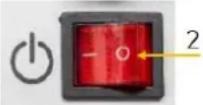 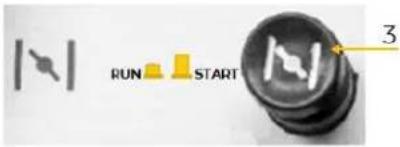 | Set the ON-OFF switch (2) to position „I“.Atcold startset the choke (3) to position „START”.If the engine runs smoothly set the choke (3) to position „RUN”.Atwarm start(the engine was running and is still warm) set choke (3) to position „RUN”.If the engine fails to start after 5 attempts, set the choke to position "START" and try again. |
 | Start the engine with the recoil starter.Grab the starter handle (4) and pull it out slowly. The resistance becomes strongest at a certain point. This point corresponds to the compression point. Let the rope roll back a little from this point and then pull it out powerfully.Slowly return the starter handle (4).If the engine does not start, try again.Normally start: 3-4 attempts. |
13.6.2 Switch the machine off
CAUTION

In case of emergency stop the machine directly with the ON-OFF switch.
Under normal circumstances, switch off the machine as follows:
- Shut down the connected devices and disconnect them from the machine.
- Let the machine run for some time without connected devices to cool down.
- Switch off the machine by putting the ON-OFF switch to position „OFF“.
- At longer breaks: Let the machine run for some time without connected devices to cool down.
- Thereafter close the fuel tap by turning to position „OFF“. The engine runs until the remaining fuel is consumed in the carburettor.
- Switch off the machine by putting the ON-OFF switch to position „0“.
13.6.3 ECO-mode

natural_image
Close-up of an electronic control panel with buttons, relays, and indicator lights (no readable text or symbols)The ECO-mode is recommended to reduce fuel consumption during operation.
With the activated ECO-mode, the machine automatically reduces the engine speed depending on the load. This results in less fuel consumption.
NOTE: In case of low power output, the ECO-mode can be activated (switch (1) in position "I").
In case of high power output and DC operation, the ECO-mode must always be deactivated (switch (1) in position "0").
B364 Teleskope handle
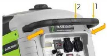
- By pressing the unlocking button (2), the length of the telescope handle (1) can be adjusted.
13.7 AC Operation
- Verify that the green indicator light (running) is on after starting the engine. This indicates that the machine is working properly.
- Check that the ON-OFF switch of the electrical devices to be used is set to "OFF".
- Connect the device to the AC-socket.
- Start the device.
NOTE: When connecting several devices, connect them in decreasing order of their kW consumption!
13.8 DC Operation
12V charging function for batteries: Before operation, observe the instructions and notes of the battery manufacturer. If the indicated charging currents/voltages of the machine are not permissible or not known for your battery, charge the battery via a battery charger to avoid damage.
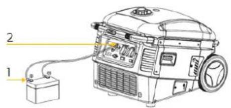

- During the direct current operation, switch off the ECO-mode. To do this, set the switch of the ECO-mode to the "0" position.
- First connected the charging cable to the DC-connection of the machine.
- Then link the charging cable to the connectors of the battery.
- Start the machine.
NOTE:
- Do not charge built-in batteries.
- Do not change the polarity of the charging cable, otherwise serious results such as damage of the machine and the battery will be caused.
- When disconnecting the charging cable, start with the battery first.
- A battery contains acid (electrolyte). Any contact with the skin or eyes will cause severe burns. Use a mask, eye protection and protective clothing
NOTE: AC and DC sockets can be used simultaneously.
An overload of the DC circuit can cause the circuit breaker 12V (3) to be activated (the pressure spring of the switch pops up). If this happens, look for possible causes.
In order to resume operation, press the DC-circuit breaker 12V (3).
14 CLEANING, MAINTENANCE, STORAGE, DISPOSAL
WARNING

Always stop the machine and let it cool down before carrying out any maintenance work and secure it against unintentional commissioning.
WARNING:
Lack of maintenance or improper maintenance and repair before using the machine can result in serious injury or death! Take therefore the safety rules, operating and maintenance instructions very seriously. Repairs only by qualified staff!
NOTE: Prevent unintentional commissioning of the machine by interrupting the fuel supply (fuel tap in position "OFF") as well as interrupting the ignition spark (remove spark plug cap of spark plug).
14.1 Cleaning
Regular cleaning guarantees the long service life of your machine and is a prerequisite for its safe operation.
NOTE: The use of solvents, aggressive chemicals or scouring agents can cause damage to the plastic parts of the machine!
Thus, when cleaning, use only water and, if necessary, mild detergents.
• We recommend cleaning the machine immediately after each use.
- Keep all safety devices, air vents and the motor housing free of dirt and dust as far as possible.
- Wipe the equipment with a moist cloth and some soft soap or blow it with compressed air at low pressure.
• Take care that any water enters the interior of the machine.
14.2 Maintenance
The machine is low-maintenance and only a few parts need to be serviced. Malfunctions or defects that could affect your safety must be repaired immediately!
• Before each operation, check the perfect condition of the safety devices.
- Regularly check the perfect and legible condition of the warning and safety labels of the machine.
• Use only proper and suitable tools.
• Use only original spare parts recommended by the manufacturer.
14.21 Maintenance plan
The type and degree of machine wear depends to a large extent on the operating conditions. The following intervals apply when the machine is used within the technical limits:
| (1) Interval can vary according to the air quality(2) Only by specialists! | Prior to each start | (for new machine) after first Month or 5 operation hours | Every 3 months or every 25 operation hours | Every 6 months or every 50 operation hours | Every 12 months or every 100 operation hours | Every 2 years or every 250 operation hours | |
| Engine oil | Control the level | X | |||||
| Change X | X | ||||||
| Air filter | Control X | ||||||
| Change | X (1) | ||||||
| Spark plug | Control | X | |||||
| Change | X | ||||||
| Fuel tank and fuel filter | Control X | ||||||
| Change | X (2) | ||||||
1422 Engine oil change
NOTE


Waste oils and fuel are toxic and must not be released into the environment!
Contact your local authorities for information on proper disposal.
Drain the used engine oil while it is still warm from operating the machine (drains easier).
natural_image
Close-up of a green and gray robotic vacuum cleaner with labeled parts (no readable text or symbols)
natural_image
Technical line drawing of a mechanical device with gears and a housing (no text or symbols)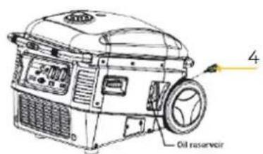

natural_image
Technical line drawing of an electric motor with attached fan and control panel (no text or symbols)
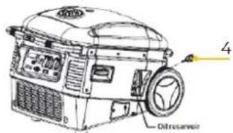
• Unscrew the dipstick (4).
- Fill in new engine oil and check the engine oil level with the dipstick (4) (regarding engine oil type and oil tank capacity see technical data).
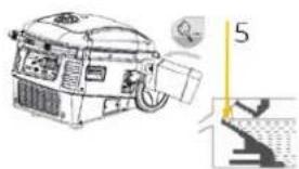
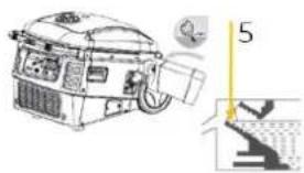
• If the oil level is correct (5), reinsert the dipstick (4).
- Remove oil residues with a cloth.
- Screw the cover (1) back on.
- Place the machine on an even surface and start the engine. If there is sufficient engine oil filled in, the low oil alarm will be not activated.
1423 Air filter
NOTE: Never operate the machine without or a not maintained air filter!
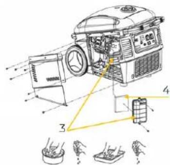
- Loosen the screws (2) and remove the cover (1).
- Loosen the screws and remove the cover of the air filter (3).
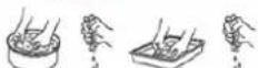
• Take out the air filter (4). - Clean the air filter with soapy water, then rinse with clear water and let it dry thoroughly before reassembling.
• The reassembly is done in reverse order.
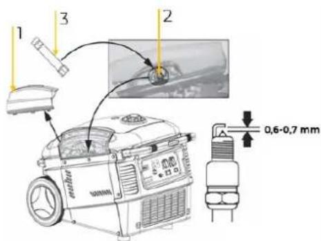
1424 Spark plug
 | Remove the spark plug cover (1).Remove the spark plug cap.Loosen the spark plug (2) using the spark plug spanner (3).Visually inspect the spark plug and remove carbon deposits with a copper wire brush.Check electrode gap. This should be between 0,6 -0,7mm.If necessary, change the spark plug.Reassemble the spark plug in reverse order. |
14.3 Storage
Storage period up to 1 month:
- No special preparation is required, only to check whether the fuel tap and the ON-OFF switch are in the "OFF" position.
Storage period longer than one month:
- Drain the fuel. To do this, run the machine without any equipment connected.
- Set the fuel tap to the "OFF" position. The engine runs until the remaining fuel in the carburetor is used up.
- Then switch the ON-OFF switch to position "0".
- Empty the fuel tank. To do this, drain the fuel and put it in a suitable container so that it does not get into the environment.
• Store the drained fuel in a suitable container. - When not in use, store the cooled down machine in a well-ventilated, dry, frost-proof and lockable place. Ensure that unauthorized persons and especially children do not have access to the machine.
NOTE

Improper storage can damage and destroy important components. Only store packed or already unpacked parts under the intended ambient conditions!
14.4 Disposal
Observe the national waste disposal regulations. Never dispose of the machine, machine components or operating equipment in the residual waste. If necessary, contact your local authorities for information regarding available disposal options.
If you purchase a new machine or equivalent equipment from your specialist dealer, he is obliged in certain countries to dispose of your old machine properly.
15 TROUBLESHOOTING
If you are unable to carry out the necessary repairs properly and/or do not have the required training, always consult a specialist to solve the problem.
| Trouble | Possible cause | Solution |
| Engine does not start | Incorrect starting sequence | Observe the correct starting sequence |
| Dirty air filter | Clean/replace air filter | |
| No fuel supply | Refuel | |
| Fault in the fuel line | Check the fuel line for kinks or damages | |
| Engine flooded | Screw off, clean and dry the spark plug. Then pull the cranking rope several times and reinstall the spark plug | |
| Spark plug connector not placed on | Place on the spark plug connector | |
| No ignition spark | Clean/replace spark plugCheck ignition cable | |
| Fuel tap closed | Open fuel tap | |
| Insufficient engine oil | Check engine oil level | |
| Engine starts and is stalled immediately | Incorrect idle adjustment | Contact the service team |
| Machine works with interruptions | Carburettor | Contact the service team |
| Spark plug fouled | Clean/replace spark plugCheck spark plug connector | |
| Low oil light glows | Check engine oil level | Fill engine oil |
| To less or no engine oil | Fill engine oil | |
| Overload indicator light glows | High temperature protection activated | Cool down the engine |
| Overload protection activated | Reduce existing load | |
| Short circuit protection activated | Check loads |
16 PRÓLOGO (ES)
¡Estimado cliente!
natural_image
Control panel with various electronic components and indicator lights (no readable text or symbols)23.1.1 Restrictions techniques
natural_image
Close-up of an electronic control panel with various switches, buttons, and a red indicator light (no readable text or symbols)natural_image
Close-up of a green and gray robotic vacuum cleaner with labeled parts (1 and 2), no visible text or symbols on the device itself.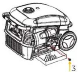
natural_image
Technical line drawing of a portable electric vehicle with visible components and mounting base (no text or symbols)

natural_image
Technical illustration of a mechanical device with a close-up view showing internal components (no text or symbols)natural_image
Close-up of a green and black industrial vacuum cleaner with labeled parts (1 and 2), no visible text or symbols on the device itself.
• Zavrtite pipico za gorivo (1) v položaj »ON«.
• Vključite stikalo za vklop/izklop (2) (položaj »I«).
- Pri hladnem zagonu postavite čok (3) na »START«.
- Ko motor mirno teče, prestavite čok (3) v položaj »RUN«.
natural_image
Close-up of an electronic control panel with buttons, relays, and indicator lights (no readable text or symbols)natural_image
Close-up of a green and gray robotic vacuum cleaner with labeled parts (1 and 2), no visible text or symbols on the device itself.
natural_image
Technical line drawing of a mechanical device with gears and housing (no text or symbols)
• Postavite stroj na vodoravno površino.
- Odvijte vijake (2) in snemite loputo za dostop do motorja (1).
- Odprite vijak za izpust motornega olja (3).
- Spustite olje v primerno posodo.
- Znova zaprite vijak za izpust motornega olja (3).
- Odvijte merilno paličico za olje (4).
- Dolijte novo motorno olje in preverite nivo olja z merilno paličico za olje (4) (tip in količino motornega olja najdete v poglavju Tehnični podatki).
- Ko je nivo olja pravilen (5), znova privijte merilno paličico za olje (4).
- Ostanke olja odstranite s krpo.
- Znova privijte loputo za dostop do motorja (1).
- Postavite stroj na vodoravno površino in zaženite motor. Če je nivo olja zadosten, kontrolna lučka za motorno olje ne zasveti.
3223 Zračni filter
natural_image
Illustration of a green and black vacuum cleaner with labeled parts (1 and 2), no text or symbols present.
- Odvijte vijake (2) stranske obloge in odstranite oblogo (1).
- Odvijte vijake pokrova zračnega filtra (3) in snemite pokrov.
• Demontirajte zračni filter (4). - Očistite zračni filter (4) z milnico, ga nato splaknite s čisto vodo in ga pred ponovno vgradnjo temeljito posušite.
- Sestava poteka v obratnem vrstnem redu.
3224 Svečke

natural_image
Close-up of industrial control panel components including buttons, switches, and indicator lights (no readable text or symbols)• Postavite stroj na ravnu površinu.
- Otpustite vijke (2) i uklonite zaklopku za pristup motoru (1).
- Otvorite čep za ispuštanje motornog ulja (3).
- Ispustite staro ulje u odgovarajuću posudu.
- Ponovno zatvorite čep za ispuštanje motornog ulja (3).
natural_image
Exterior view of a compact vacuum cleaner with green and black casing (no visible text or symbols)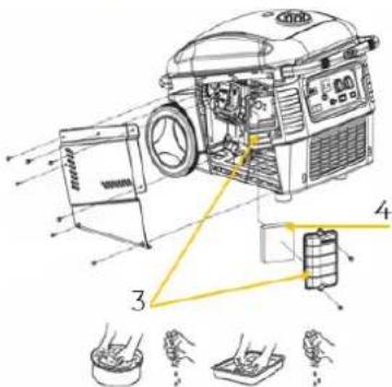
- Otpustite vijke (2) bočnog poklopca i uklonite poklopac (1).
- Otpustite vijke poklopca zračnog filtra (3) i uklonite poklopac.
- Izvadite zračni filtar (4).
- Očistite zračni filtar (4) sapunicom, zatim ga isperite čistom vodom i ostavite da se temeljito osuši prije ponovnog postavljanja.
- Ponovno sastavljanje se vrši obrnutim redoslijedom.
3824 Svjećica
flowchart
graph TD
    A["INVIC socket"] --> B["Red-23W"]
    B --> C["AC-230V socket1A"]
    C --> D["Black-1.5m2"]
    D --> E["White"]
    E --> F["Red"]
    F --> G["Yellow-green-23W"]
    G --> H["Main circuit power device"]
    H --> I["Power control module"]
    I --> J["Microprocessor"]
    J --> K["Stepper motor control module"]
    K --> L["Secondary winding"]
    L --> M["Irrigation winding"]
    M --> N["DC Winding"]
    N --> O["White-lock"]
    O --> P["White-lock"]
    P --> Q["Three-phase primary winding"]
    Q --> R["Black-16W"]
    R --> S["Black-16W"]
    S --> T["Blue-16W"]
    T --> U["Blue-16W"]
    U --> V["Red"]
    V --> W["Red"]
    W --> X["Black White"]
    X --> Y["Yellow-green"]
    Y --> Z["Stepper motor"]
    Z --> AA["Digital Display-KWH"]
    AA --> AB["Start Switch"]
    AB --> AC["Blue Red"]
    AC --> AD["Yellow"]
    AD --> AE["Irrigation Trigger"]
    AE --> AF["Black"]
    AF --> AG["Irrigation coil"]
    AG --> AH["Spark 2.0g"]
    AH --> AI["Oil sensor"]
    AI --> AJ["Yellow-green"]
    AJ --> AK["Low oil light"]
    AK --> AL["Fault Indicator"]
    AL --> AM["Work indicator + Green"]
    AM --> AN["Overload indicator - Yellow"]
    AN --> AO["Overload indicator + Red"]
    AO --> AP["Yellow Brown"]
    AP --> AQ["Irrigation Trigger"]
    AQ --> AR["Fault Indicator"]
    AR --> AS["Irrigation coil"]
41 ERSATZTEILE / SPARE PARTS
/ PIEZAS DE RECAMBIO / Schéma électrique / NADOMESTNI DELI / REZERVNI DIJELOVI
41.1 Ersatzteilbestellung / Spare parts order / Pedido de piezas / Commande de pièces détachées / Naročanje nadomestnih delov / Narudžba rezervnih dijelova
(EN) With original ZIPPER spare parts you use parts that are attuned to each other shorten the installation time and elongate your products lifespan.
NOTE

The installation of parts other than original spare parts leads to the loss of the guarantee! Therefore: When replacing components/parts, only use spare parts recommended by the manufacturer.
Order the spare parts directly on our homepage – category SPARE PARTS or contact our customer service
• via our Homepage – category SERVICE/NEWS - SPARE PARTS REQUEST,
• by e-mail to eg01@zipper-maschinen.at.
Always state the machine type, spare part number and designation. To prevent misunderstandings, we recommend that you add a copy of the spare parts drawing with the spare parts order, on which the required spare parts are clearly marked, especially when not using the online-spare-part catalogue.
41.3 Ersatzteilliste / Spare parts list / Listado de piezas de recambio / Liste des pièces de rechange / Seznam nadomestnih delov / Popis rezervnih dijelova
| No. | Name | Qty. | No. | Name | Qty. |
| 1 | Gas Cap | 1 | 41 | M6 X 50 Allen Head Bolt | 3 |
| 2 | Fuel Strainer | 1 | 42 | Stator | 1 |
| 3 | Fuel Tank Grommet | 1 | 43 | Engine Cover, Lower | 1 |
| 4 | Top Cover | 1 | 44 | Air Filter Cover Screw | 1 |
| 5 | M6 X 14 Flange Bolt | 4 | 45 | Air Filter Cover | 1 |
| 6 | Fuel Tank Isolator | 4 | 46 | Air Filter Element | 1 |
| 7 | Carbon Canister Hose | 1 | 47 | M6 Serrated Flange Nut | 2 |
| 8 | Fuel Level Sight Glass | 1 | 48 | Air Filter Case | 1 |
| 9 | Fuel Level Indicator | 1 | 49 | Breather Tube | 2 |
| 10 | Fuel Tank | 1 | 50 | Carburetor Gasket 1 | 1 |
| 11 | Fuel Valve | 1 | 51 | Choke Plate | 1 |
| 12 | ∅8 Fuel Hose | 1 | 52 | Carburetor Gasket 1 | 1 |
| 13 | ∅7.8 Hose Clamp | 2 | 53 | Step Motor Bracket | 1 |
| 14 | Frame, Upper | 1 | 54 | Step Motor | 1 |
| 15 | Handle Guide Sleeve | 2 | 55 | ST4 X 10 Screw | 2 |
| 16 | Front Cover,Upper | 1 | 56 | M4 X 12 Screw | 2 |
| 17 | M6 X 16 Allen Screw | 2 | 57 | Carburetor | 1 |
| 18 | Handle Cap Assembly | 2 | 58 | Carburetor Gasket 2 | 1 |
| 19 | Handle Push Pad | 2 | 59 | Carburetor Insulator Block | 1 |
| 20 | Handle Push Rod | 2 | 60 | Carburetor Rubber Gasket | 1 |
| 21 | Handle Tube | 2 | 61 | Carburetor Gasket 3 | 1 |
| 22 | M4 X 10 Screw | 2 | 62 | Ignition Coil | 1 |
| 23 | ST5 X 16 Screw | 2 | 63 | M6 X 14 Flange Bolt | 2 |
| 24 | Handle | 1 | 64 | Engine Assy, 170F | 1 |
| 25 | Handle Release | 1 | 65 | Trigger | 1 |
| 26 | Handle Cover | 1 | 66 | M6 X 10 Flange Bolt | 1 |
| 27 | M6 X 8 Flange Bolt | 7 | 67 | Engine Cover | 1 |
| 28 | Recoil Starter | 1 | 68 | M6 X 14 Flange Bolt | 2 |
| 29 | Rope Guide | 1 | 69 | Engine Cover, Upper | 1 |
| 30 | Vibration Absorber | 4 | 70 | M6 X 22 Flange Bolt | 2 |
| 31 | M8 Serrated Flange Nut | 4 | 71 | M6 X 14 Flange Bolt | 1 |
| 32 | Fan Cover, 3000Wi | 1 | 72 | Exhaust Manifold Gasket | 2 |
| 33 | M6 X 14 Flange Bolt | 4 | 73 | Exhaust Manifold | 1 |
| 34 | M6 X 8 Flange Bolt | 3 | 74 | M8 Serrated Flange Nut | 2 |
| 35 | Starter Cup | 1 | 75 | Muffler | 1 |
| 36 | M6 X 10 Flange Bolt | 4 | 76 | M8 X 60 Flange Bolt | 2 |
| 37 | Starter Cup Base | 1 | 77 | M8 X 40 Flange Bolt | 1 |
| 38 | Intake Fan | 1 | 78 | ST4 X 10 Screw | 1 |
| 39 | M14 Serrated Flange Nut | 1 | 79 | Spark Arrestor | 1 |
| 40 | Rotor | 1 | 80 | Muffler Cover | 1 |
| 81 | Rear Handle | 1 | 118 | Carbon Canister Bracket | 1 |
| 82 | M6 X 16 Allen Screw | 2 | 119 | M6 X 8 Flange Bolt | 2 |
| 83 | M6 X 12 Screw | 5 | 120 | Carbon Canister Hose 2 | 1 |
| 84 | Muffler Cover Gasket | 1 | 121 | Carbon Canister | 1 |
| 85 | Choke Lever | 1 | 122 | Bottom Cover | 1 |
| 86 | M5 X 10 Screw | 1 | 123 | Rubber Foot | 2 |
| 87 | Knob, Fuel Valve | 1 | 124 | M5 X 12 Flange Bolt | 5 |
| 88 | Rocker Switch, Engine | 1 | 125 | M5 X 10 Allen Screw | 1 |
| 89 | Circuit Breaker Nut | 2 | 126 | M5 X 16 Allen Screw | 2 |
| 90 | Rocker Switch, Economy | 1 | 128 | M5 X 8 Allen Screw | 3 |
| 91 | DC Socket, T Style | 1 | 129 | Left Maintenance Cover | 1 |
| 92 | M4 X 10 Screw | 2 | 130 | Left Side Cover | 1 |
| 93 | M5 X 10 Screw | 2 | 131 | M8 X 40 Flange Bolt | 2 |
| 94 | M4 X 10 Screw | 4 | 132 | Frame, Lower | 1 |
| 95 | M5 Nut | 2 | 133 | M5*18 Flange Bolt | 1 |
| 96 | Control Panel | 1 | 134 | Voltage Regulator | 1 |
| 97 | Grounding Lug | 1 | 135 | M8 Serrated Flange Nut | 4 |
| 98 | Choke Lever Nut | 1 | 136 | M8 X 40 Flange Bolt | 2 |
| 99 | LCD Display | 1 | 137 | M5 X 16 Allen Screw | 2 |
| 100 | M4 Nut | 2 | 138 | M5 Criclip | 2 |
| 101 | Indicator Module | 1 | 139 | Right Side Cover | 1 |
| 102 | M6 X 12 Serrated Flange Bolt | 1 | 140 | Oil Drain Cover | 1 |
| 103 | AC Circuit Breaker, 20A | 1 | 141 | M5 X 10 Allen Screw | 2 |
| 104 | AC Circuit Breaker, 30A | 1 | 142 | M5 X 10 Allen Screw | 1 |
| 105 | 120~20A 5-20R Sing. Receptacle | 1 | 143 | Oil Access Cover | 1 |
| 106 | 120V-30A L5-30 Receptacle | 1 | 144 | M5 X 8 Allen Screw | 3 |
| 107 | M4 Nut | 4 | 145 | Right Maintenance Cover | 1 |
| 108 | M6 X 16 Allen Screw | 2 | 146 | Wheel Cover | 1 |
| 109 | M5 X 10 Allen Screw | 2 | 147 | M10 Serrated Flange Nut | 1 |
| 110 | M6 X 16 Allen Screw | 2 | 148 | Wheel | 1 |
| 111 | Front Cover, Lower | 1 | 149 | Wheel Axle | 1 |
| 112 | M5 Clip Nut | 2 | 150 | Rear Cover | 1 |
| 113 | M6 X 14 Flange Bolt | 2 | 151 | M5 Clip Nut | 2 |
| 114 | Inverter Grommet | 2 | 152 | M6 X 16 Allen Screw | 2 |
| 115 | Inverter Assembly | 1 | 153 | Exhaust Grill | 1 |
| 116 | Inverter Vibration Absorber | 2 | 154 | M5 X 16 Allen Screw | 4 |
| 117 | M5 X 20 Flange Bolt | 2 |
Company ZIPPER Maschinen GmbH grants for mechanical and electrical components a warranty period of 2 years for amateur use; and warranty period of 1 year for professional use, starting with the purchase of the final consumer. In case of defects during this period, which are not excluded by paragraph 3, ZIPPER will repair or replace the machine at its own discretion.
2.) Report:
In order to check the legitimacy of warranty claims, the final consumer must contact his dealer. The dealer has to report in written form the occurred defect to ZIPPER. If the warranty claim is legitimate, ZIPPER will pick up the defective machine from the dealer. Returned shippings by dealers which have not been coordinated with ZIPPER, will not be accepted and refused.
3.) Regulations:
a) Warranty claims will only be accepted, when a copy of the original invoice or cash voucher from the trading partner of ZIPPER is enclosed to the machine. The warranty claim expires if the accessories belonging to the machine are missing.
b) The warranty does not include free checking, maintenance, inspection or service works on the machine. Defects due to incorrect usage of the final consumer or his dealer will not be accepted as warranty claims either. Some examples: usage of wrong fuel, frost damages in water tanks, leaving fuel in the tank during the winter, etc.
c) Defects on wear parts are excluded, e.g. carbon brushes, collection bags, knives, cylinders, cutting blades, clutches, sealings, wheels, saw blades, splitting crosses, riving knives, riving knife extensions, hydraulic oils, oil/air/fuel filters, chains, spark plugs, sliding blocks, etc.
d) Also excluded are damages on the machine caused by incorrect or inappropriate usage, if it was used for a purpose which the machine is not supposed to, ignoring the user manual, force majeure, repairs or technical manipulations by not authorized workshops or by the customer himself, usage of non-original ZIPPER spare parts or accessories.
e) After inspection by our qualified personnel, resulted costs (like freight charges) and expenses for not legitimated warranty claims will be charged to the final customer or dealer.
f) In case of defective machines outside the warranty period, we will only repair after advance payment or dealer's invoice according to the cost estimate (incl. freight costs) of ZIPPER.
g) Warranty claims can only be granted for customers of an authorized ZIPPER dealer who directly purchased the machine from ZIPPER. These claims are not transferable in case of multiple sales of the machine.
4.) Claims for compensation and other liabilities:
The liability of company ZIPPER is limited to the value of goods in all cases. Claims for compensation because of poor performance, lacks, damages or loss of earnings due to defects during the warranty period will not be accepted. ZIPPER insists on its right to subsequent improvement of the machine.
SERVICE
After Guarantee and warranty expiration specialist repair shops can perform maintenance and repair jobs. But we are still at your service as well with spare parts and/or product service. Place your spare part/repair service cost inquiry by
- Mail to service@zipper-maschinen.at.
- Or use the online complaint order formula provided on our homepage – category service/news.
(EN) We monitor the quality of our delivered products in the frame of a Quality Management policy.
Your opinion is essential for further product development and product choice. Please let us know about your:
- Impressions and suggestions for improvement.
- Experiences that may be useful for other users and for product design
- Experiences with malfunctions that occur in specific operation modes
We would like to ask you to note down your experiences and observations and send them to us via E-Mail or by post:


- ZI-STE3000IV
- INHALT / INDEX
- Technische Daten / Technical data / Datos técnicos / Données techniques / Tehnični podatki / Tehnički podaci
- VORWORT (DE)
- Please read and note the safety instructions!
- Copyright
- Customer service contact
- Intended use of the machine
- NOTE
- II.1.1 Technical restrictions
- Prohibited applications / Dangerous misuse
- User Requirements
- General safety instructions
- Electrical safety
- Special safety instructions for this machine
- Safety instructions for machines with combustion engine
- Hazard warnings
- Residual risks
- - Risk of burns:
- • Risk of fire and explosion:
- - Chemical risks
- - Risk of electric shock
- - Hearing damage
- T1.72 Hazardous situations
- DANGER
- WARNING
- CAUTION
- TRANSPORT
- OPERATION
- Preparation
- Checking delivery content
- Requirements for the installation site
- Pre-operation check
- Check engine oil level
- Check fuel tank level
- Never refuel if the engine is running
- B23 Grounding
- Information on Initial Start-up
- Test Run Initial Start-up
- Switching on the machine by an electrical amateur
- Operating instructions
- Operation of the machine to over 1500m above sea level
- Connecting devices
- Operation
- Switch the engine/machine on
- Switch the machine off
- Under normal circumstances, switch off the machine as follows:
- ECO-mode
- B364 Teleskope handle
- AC Operation
- DC Operation
- NOTE:
- CLEANING, MAINTENANCE, STORAGE, DISPOSAL
- WARNING:
- Cleaning
- NOTE: The use of solvents, aggressive chemicals or scouring agents can cause damage to the plastic parts of the machine!
- Maintenance
- Maintenance plan
- Engine oil change
- Waste oils and fuel are toxic and must not be released into the environment!
- Air filter
- Spark plug
- Storage
- Storage period up to 1 month:
- Storage period longer than one month:
- Disposal
- TROUBLESHOOTING
- PRÓLOGO (ES)
- ¡Estimado cliente!
- Restrictions techniques
- Zračni filter
- Svečke
- Svjećica
- ERSATZTEILE / SPARE PARTS
- Ersatzteilbestellung / Spare parts order / Pedido de piezas / Commande de pièces détachées / Naročanje nadomestnih delov / Narudžba rezervnih dijelova
- 2.) Report:
- 3.) Regulations:
- 4.) Claims for compensation and other liabilities:
- SERVICE
Brand : Zipper
Model : ZISTE3000IV
Category : Generator