
ZISTE5500 - Generator Zipper - Free user manual and instructions
Find the device manual for free ZISTE5500 Zipper in PDF.
| Brand | Zipper |
| Model | ZISTE5500 |
| Product Type | Portable Generator |
| Rated Power | 5.5 kW (5500 W) |
| Output Voltage | 230 V AC |
| Frequency | 50 Hz |
| Engine Type | 4-Stroke Gasoline Engine |
| Fuel | Unleaded 95 Octane Gasoline |
| Engine Oil | SAE 10W-30 (check level before use) |
| Starting System | Manual (recoil) and Electric (remote control) |
| Fuel Tank Capacity | Approximately 25 L (estimate) |
| Runtime | Approximately 8 hours at 50% load (estimate) |
| Built-in Protection | Low oil shutdown, overload circuit breaker |
| Outlets | AC 230 V outlets, DC outlet (not specified) |
| Grounding | Recommended by a qualified electrician |
| Noise Level | Approximately 95 dB(A) (estimate) |
| Maintenance | Oil change every 50 h, air filter every 50 h, spark plug every 100 h |
| Operating Temperature | +5°C to +40°C |
| Maximum Altitude | 1800 m (carburetor adjustment required) |
| Warranty | 2 years non-professional use, 1 year professional use |
| Spare Parts | Use genuine Zipper parts |
Frequently Asked Questions - ZISTE5500 Zipper
User questions about ZISTE5500 Zipper
0 question about this device. Answer the ones you know or ask your own.
Ask a new question about this device
Download the instructions for your Generator in PDF format for free! Find your manual ZISTE5500 - Zipper and take your electronic device back in hand. On this page are published all the documents necessary for the use of your device. ZISTE5500 by Zipper.
USER MANUAL ZISTE5500 Zipper
natural_image
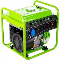
Green portable electricity generator with wheels and control panel (no visible text or symbols)ZI-STE2800
EAN: 9120039231518
natural_image
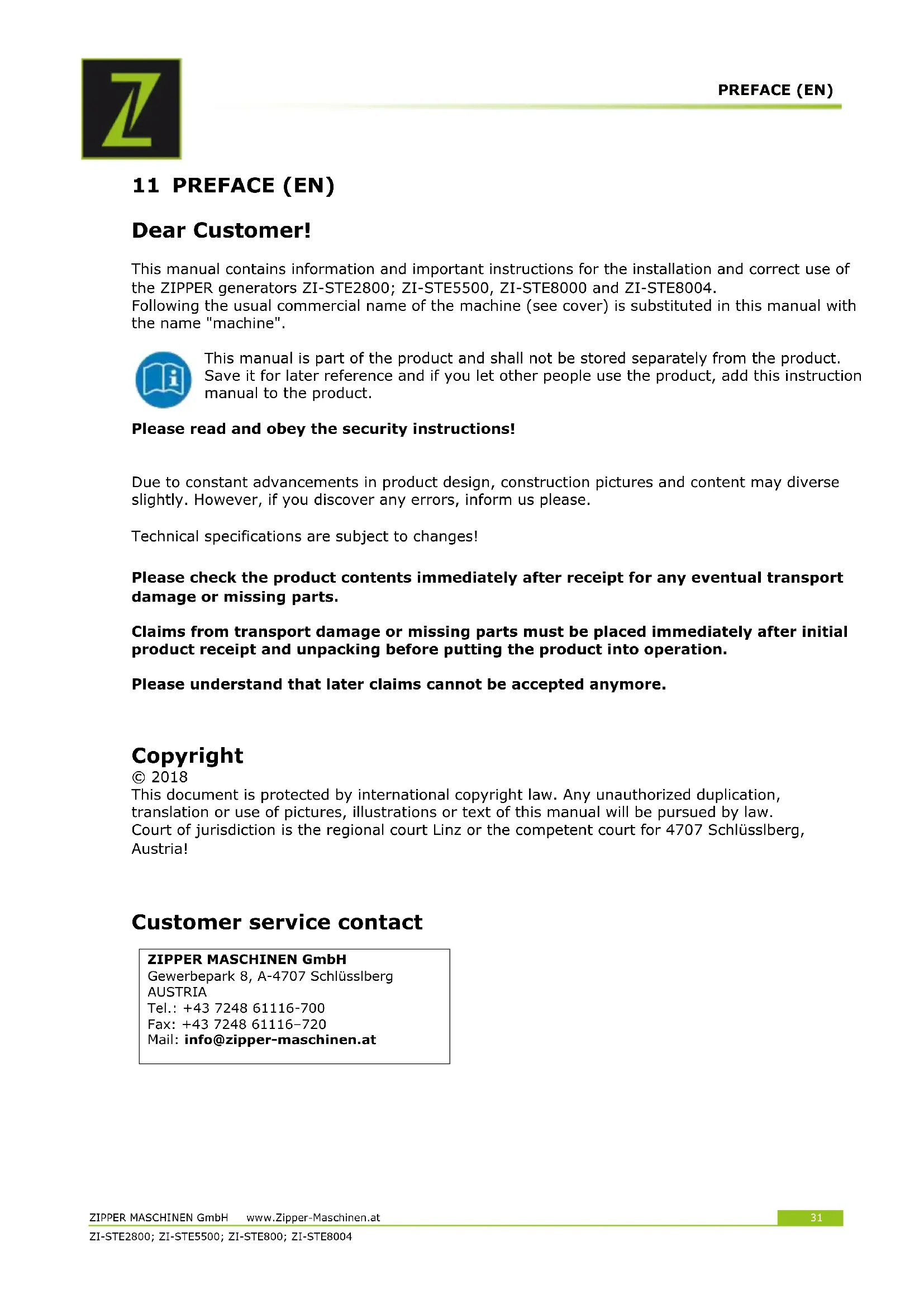
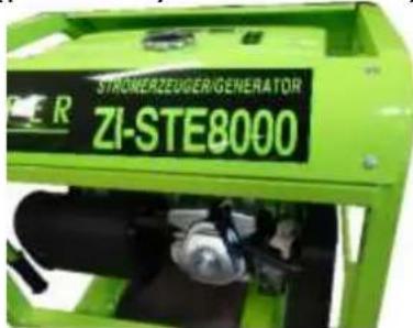
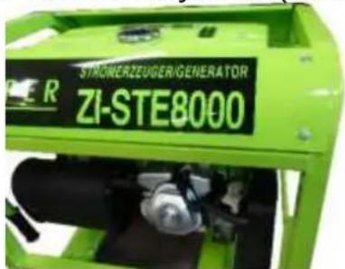
Green ZIPPER ZI-STE8000 industrial power plant with wheels and control panel (no visible text or symbols on device body)ZI-STE8000
EAN: 9120039231525
natural_image
Green portable electricity generator with wheels and control panel (no visible text or symbols)ZI-STE5500
EAN: 9120039232249
natural_image
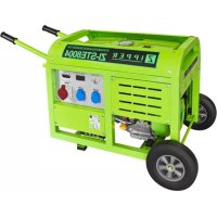
Green industrial power plant with visible control panel and wheels (no text or symbols on main body)ZI-STE8004
EAN: 9120039231815
1 INHALT/ INDEX
1 INHALT/ INDEX 2
12.1 Intended use of the machine 32
12.1.1 Technical Restrictions 32
12.1.2 Prohibited Use / Forseeable Misuse 32
12.2 User Requirements....32
12.3 Safety instructions .... 33
12.4 Special safety instructions for the operation of the machine 33
12.5 Safety instructions for machines with combustion engine....33
12.6 Hazard warnings 34
13 ASSEMBLY 34
13.1 Check scope of delivery 34
13.2 Assembly 34
13.2.1 ZI-STE2800 34
13.2.2 ZI-STE5500 35
13.2.3 ZI-STE8000 / ZI-STE8004 35
13.3 Checklist before each use 36
13.3.1 Checking the engine oil level 36
13.3.2 Checking the fuel tank level 37
14 OPERATION 37
14.1 Information on Initial Start-up....37
14.1.1 Grounding 37
14.1.2 Test Run Initial Start-up 37
14.1.3 Notes on the first 20 operating hours.... 37
14.2 Operating Instructions 37
14.2.1 Integration into an existing electricity grid.... 37
14.2.2 Devices are connected to the AC terminals 38
14.2.3 Operation of the generator to over 1800m above sea level.... 38
14.3 AC Operation 38
14.4 Operation 39
14.4.1 Start (for ZI-STE2800 and ZI-STE5500) 39
14.4.2 Start (for ZI-STE8000 and ZI-STE8004) 40
14.4.3 Stop 40
15 MAINTENANCE
15.1 Maintenance plan 41
15.1.1 Changing the engine oil 41
15.1.2 Air filter 42
15.1.3 Spark plug 42
15.1.4 Fuel Tank & Filter Valve (every 150 hours) 43
15.2 Transport....43
15.3 Storage....43
16 DISPOSAL
17 TROUBLESHOOTING 44
18 PREFACIO (ES) 45
19 SEGURIDAD 46
19.1 Uso adecuado 46
EN CE-Conformal! - This product complies with the EC-directives.
EN Follow the instructions!
EN No open flame, fire, open source of ignition and smoking prohibited!
EN Danger of Intoxication (CO)! Only use outdoors and far from open windows and vents!
EN Keep safe distance!
EN Protect from moisture!
EN Warning of flammable liquids; turn off the engine before filling (gasoline)
ES
EN ATTENTION: Check Oil! Engine don't start with low oil!!
EN Warning signs and/or stickers on the machine which are illegible or have been removed must be replaced immediately!
3.1.3 ZI-STE8000
3.1.4 ZI-STE8004
| 1 | Stromerzeuger; Generator/ Generador/ Générateur/ Elektrocentrála/ Elektrocentrála/ Generator/ Električni generator/ |
| 2 | Griff / Handle /asa / Poignée / Transportná rukovát / Transportní rukojeť / Transportna ročica / Transportna ručka |
| 3 | Halterung Griff / handle holder / Abrazadera del asa / Pince de la poignée de transport |
| 4 | Befestigung Griff / handle mounting / asa de montaje / Poignée de montage |
| 5 | Gummifüße / rubber feet / Pies de apoyo / Pieds de support / Nožička stojana / Nožička stojanu / Stojalo |
| 6 | Räder / wheels / ruedes / Roues / Kolečko / Kolo / Kotač |
| 7 | Achsen / axis /eje / Arbre Os kolesa / Osovina kotača |
| 8 | Stecker / plug |
| 9 | Zündkerzenschlüssel / spark plug key / llave de bujías / clé à bougie / klúčov a sviečky / ključem za vžigalne svečke / ključ za svječice |
| 10 | Werkzeug / tools |
| 11 | Kleinteile / Hardware |
| 12 | Bedienungsanleitung / Manual Machine / Manual de instrucciones / Mode d'emploi / Návod na použitie stroja / Návod k použití / Navodilo za delo s strojem / Uputa za uporabu stroja / |
| 13 | Einfülltrichter Motoröl / funnel engine oil / Embudo para aceite / Entonnoir de remplissage huile moteur / Plniaci otvor motorového oleja /Návod k použití / Iijak za polnjenje motornega olja / Lijevak za motorno ulje /Motorolaj-betöltő tölcsér |
| 14 | Startschlüssel / starting key / llave de contacto / clef de contact |
| 15 | Funkstarter / remote control starter / control remoto de arranque/ commande de démarrage à distance |
3.2 Komponenten / components
3.2.1 ZI-STE2800
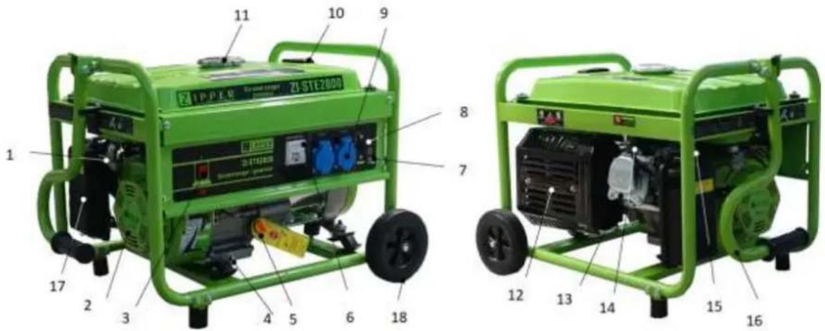
| 1 | Treibstoffventil / fuel valve / válvula de combustible / robinet de carburant/ Palivový kohútik /Palivový kohout /ventil za gorivo /Ventil za gorivo / | 10 | Kraftstoffanzeige / fuel indication / indicador de combustible / indicateur de carburant |
| 2 | Reversierstarter / recoil starter / Arrancador inverso / Démarreur inverseur Šartovacia šnúra / Rukojeť startovací šňůry Reverzijski zaganjač / Ručka startera | 11 | Tankdeckel/ fuel filler cap / tapón del depósito / bouchon du réservoir / Zátka nádrže / Zátka nádrže / pokrov rezervoarja / Poklopac spremnika |
| 3 | Ein-Aus-Schalter / On-Off-switch / Interruptor ON-OFF / Interrupteur ON-OFF Vypínač zapalovania / Vypínač zapalování / Stikalo za vžig / Prekidač za paljenje | 12 | Auspuff / muffler / silenciador / silencieux / Výfuk /Výfuk / izpuh / Ispuh / |
| 4 | Motoröl-Ablassschraube / oil drain plug / tapón de drenaje de aceite / bouchon de vidange d'huile Výpustná skrutka oleja /Výpustný šroub oleje / vijak za izpust olja / Vijak za ispuštanje motornog ulja | 13 | Motor / motor / motor / moteur / motor / motor |
| 5 | Olmessstab / dipstick / Varilla de nivel de aceite / Jauge d'huile Mierka oleja v motore / Měrka oleje v motoru Merilna palica za olje / Štapić za mjerenje razine ulja | 14 | Zündkerze / spark plug / bujía / bougie / Sviečka /Svička Vtikač za svečko -svečka / Svjećica |
| 6 | Voltmeter / voltmeter / Voltímetro / Voltmètre Voltmeter /Voltmetr / Voltmeter / Voltmetar | 15 | Choke-Hebel / choke lever / palanca de cebador / starter / Škrtiaca klapka /Škrtící klapka/ ročica za zaug / Ručica za čok /Szívató kar |
| 7 | Erdungsklemme / grounding pole / Toma de tierra / Mise à terre Zemniaca svorka / Zemníci svorka Ozemljitveni priključek / Poluga uzemljenja | 16 | Transportgriff / handle / asa/ Poignée de transport Transportná rukovát / Transportní rukojeť Transportna ročica / Transportna ručka |
| 8 | Schutzschalter / breaker / Interruptor de protección / Interrupteur de protection Poistka /Pojistka / Varovalni avtomat / Osigurač | 17 | Luftfilter / air filters / filtros de aire / filtre à air / Vzduchový filter /vzduchový filtr / zračni filter /Filtar za zrak / |
| 9 | 2x230V Steckdose / 2x 230V sockets / 2x Toma de 230V / 2x Prise de 230V/ Objem olejové nádrže / 230V zásuvka / Varnostna vtičnica 230V / AC utičnica | 18 | Räder /wheels / rueda / Roues / Koliesko / Kolečko / Kolo / Kotač |
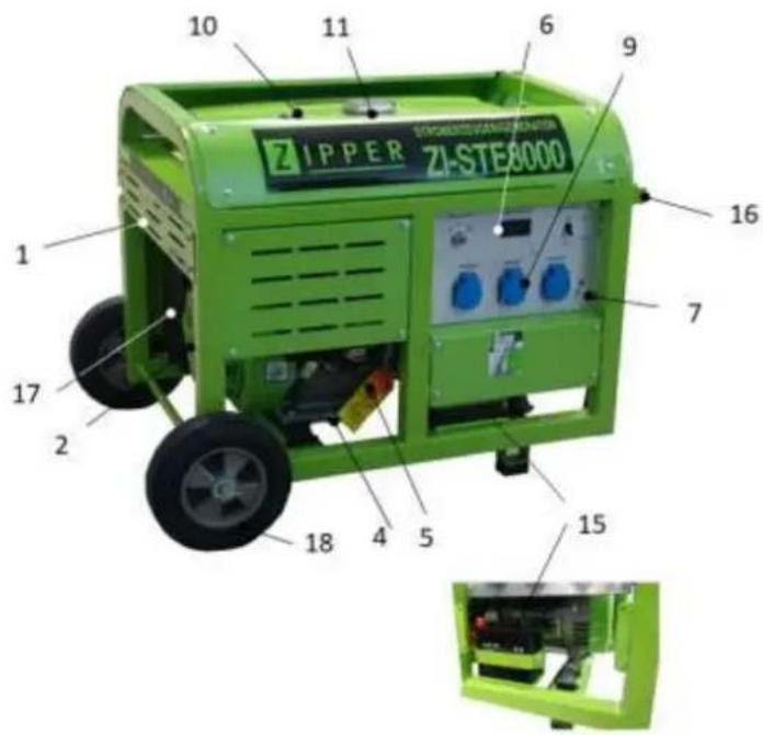
3.2.2 ZI-STE5500

| 1 | Treibstoffventil / fuel valve /válvula de combustible / robinet de carburant/Palivový kohútik /Palivový kohout /ventil za gorivo /Ventil za gorivo / | 10 | Kraftstoffanzeige / fuel indication /indicador de combustible / indicateur de carburant |
| 2 | Reversierstarter / recoil starter /Arrancador inverso / Démarreur inverseurŠtartovacia šnúra / Rukojeť startovací šňůryReverzijski zaganjač / Ručka startera | 11 | Tankdeckel/ fuel filler cap /tapón del depósito / bouchon du réservoir /Zátka nádrže / Zátka nádrže /pokrov rezervoarja / Poklopac spremnika |
| 3 | Ein-Aus-Schalter / On-Off-switch /Interruptor ON-OFF / Interrupteur ON-OFFVypínač zapalovania / Vypínač zapalování /Stikalo za vžig / Prekidač za paljenje | 12 | Auspuff / muffler /silenciador / silencieux /Výfuk /Výfuk /izpuh / Ispuh / |
| 4 | Motoröl-Ablassschraube / oil drain plug /tapón de drenaje de aceite / bouchon de vidange d'huileVýpustná skrutka oleja /Výpustný šroub oleje /vijak za izpust olja / Vijak za ispuštanje motornog ulja | 13 | Motor / motor /motor / moteur /motor / motor |
| 5 | Ölmessstab / dipstick /Varilla de nivel de aceite / Jauge d'huileMierka oleja v motore / Měrka oleje v motoruMerilna palica za olje / Štapić za mjerenje razine ulja | 14 | Zündkerze / spark plug /bujía / bougie /Sviečka /SvičkaVtikač za svečko -svečka / Svjećica |
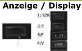
| 6 | Anzeige (V+F+T); Display (V+F+T) | 15 | Choke-Hebel / choke lever /palanca de cebador / starter /Škrtiaca klapka /Škrtící klapka/ročica za zaug / Ručica za čok /Szívató kar |
| 7 | Erdungsklemme / grounding pole /Toma de tierra / Mise à terreZemniaca svorka / Zemnící svorkaOzemljitveni priključek / Poluga uzemljenja | 16 | Transportgriff / handle /asa/ Poignée de transportTransportná rukovat’ / Transportní rukojeťTransportna ročica / Transportna ručka |
| 8 | Schutzschalter / breaker / Interruptor de protección /Interrupteur de protectionPoistka /Pojistka / Varovalní avtomat / Osigurač | 17 | Luftfilter / air filters /filtros de aire / filtre à air /Vzduchový filter /vzduchový filtr /zrační filter /Filtar za zrak / |
| 9 | 1x 230V + 1x 400VSteckdose / sockets / Toma / Prise /Objem olejové nádrže / zásuvka /Varnostna vtičnica / AC utičnica | 18 | Räder /wheels / rueda / Roues / Koliesko / Kolečko /Kolo / Kotač |
Anzeige / Display

3.2.1 ZI-STE8000 / ZI-STE8004


| 1 | Treibstoffventil / fuel valve / válvula de combustible / robinet de carburant/ Palivový kohútik /Palivový kohout / ventil za gorivo /Ventil za gorivo / | 10 | Kraftstoffanzeige / fuel indication / indicador de combustible / indicateur de carburant |
| 2 | Reversierstarter / recoil starter / Arrancador inverso / Démarreur inverseur Šartovacia šnúra / Rukojeť startovací šňůry Reverzijski zaganjač / Ručka startera | 11 | Tankdeckel/ fuel filler cap / tapón del depósito / bouchon du réservoir / Zátka nádrže / Zátka nádrže / pokrov rezervoarja / Poklopac spremnika |
| 3 | Ein-Aus-Schalter / On-Off-switch / Interruptor ON-OFF / Interrupteur ON-OFF Vypínač zapalovania / Vypínač zapalováni / Stikalo za vžig / Prekidač za paljenje | 12 | Auspuff / muffler / silenciador / silencieux / Výfuk /Výfuk / izpuh / Ispuh / |
| 4 | Motoröl-Ablassschraube / oil drain plug / tapón de drenaje de aceite / bouchon de vidange d'huile Výpustná skrutka oleja /Výpustný šroub oleje / vijak za izpust olja / Vijak za ispuštanje motornog ulja | 13 | Motor / motor / motor / moteur / motor / motor |
| 5 | Ölmessstab / dipstick / Varilla de nivel de aceite / Jauge d'huile Mierka oleja v motore / Měrka oleje v motoru Merilna palica za olje / Štapić za mjerenje razine ulja | 14 | Zündkerze / spark plug / bujía / bougie /Sviečka /Svíčka Vtikač za svečko -svečka / Svjećica |
| 6 | Anzeige (V+F+T); Display (V+F+T) | 15 | Batterie / battery |
| 7 | Erdungsklemme / grounding pole / Toma de tierra / Mise à terre Zemniaca svorka / Zemníci svorka Ozemljitveni priključek / Poluga uzemljenja | 16 | Transportgriff / handle / asa/ Poignée de transport Transportná rukováť / Transportní rukojeť Transportna ročica / Transportna ručka |
| 8 | Schutzschalter / breaker / Interruptor de protección / Interrupteur de protection Poistka /Pojistka / Varovalni avtomat / Osigurač | 17 | Luftfilter / air filters / filtros de aire / filtre à air / Vzduchový filter /vzduchový filtr / zračni filter /Filtar za zrak / |
| 9 | 3x 230V (ZI-STE8000) 2x230V + 1x 400V (ZI-STE8004( Steckdose / sockets / Toma / Prise / Objem olejové nádrže / zásuvka / Varnostna vtičnica / AC utičnica | 18 | Räder /wheels / rueda / Roues / Koliesko / Kolečko / Kolo / Kotač |
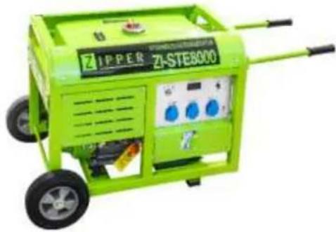
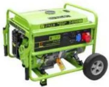
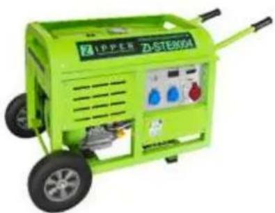
3.3 Technische Daten / Technical date / Ficha técnica /
Fiche technique /Technická data /Tehnični podatki /Tehnički podaci
| ZI-STE2800 | ZI-STE5500 | ZI-STE8000 | ZI-STE8004 | |
| Motor, engine, Motor , Moteur , Motorja, motor ;motora | HP170F | HP190F | HP192F | HP192F |
| Hubraum / displacement / Cilindrada / Déplacement / Objem motora /Objem motoru / Delovna prostornina / Kapacitet /zapremina | 212ccm | 420ccm | 460ccm | 460ccm |
| Motorleistung / engine power/ potencia del motor / puissance moteurVýkon motora / Výkon motoru/moč motorja / Snaga motora | 4.0kW | 8,5kW | 9,3kW | 9,3kW |
| Motordrehzahl / engine speed / Velocidad del motor / Vitesse du moteur / Otáčky / Otáčky / Število vrtljajev / Brzina motora | 3600min-1 | |||
| Kraftstoff / fuel /Combustible / carburant /Palivo /Palivo /gorivo / Gorivo / | bleifreies Benzin, unleaded fuel (95 ROZ)gasolina sin plomo, essence sans plombbezolovnatý benzin /bezolovni benzin (95 ROZ)neosvinčeni bencin. | |||
| Starter / starter / Arrancador / Démarreur /Startér / Startér / Zaganjač / Paljenje/starter | Seilzug /recoilTCI -cable / TCI -cableTCI / Startovaci šňůrataTCI / Startovaci šňůrataTCI / na vrvicoTCI/kontrola kabla | Elektrisch/ electriceléctrico /électriqueelektrostart / elektrostartelektrični zagon / Električno paljenje | ||
| Batterietyp / battery-type | - | - | PB | PB |
| Schutzklasse / Protection mode / Protección / Classe de protection /xx / Krytí / Vrsta zaščite / Klasa zaštite | IP23M | IP23M | IP23M | IP23M |
| Öltankvolumen / oil-tank capacity /Capacidad depósito de aceite / volume du réservoir d'huile /Objem olejové nádrže / Objem olejové nádrže / Kapaciteta rezervoarja za olje/Kapacitet spremnika ulja | 600ml | 1100ml | 1100ml | 1100ml |
| empfohlenes Motoról / recommended engine oil /aceite de motor / Huile moteur / motorový olej / motorovýolej / motorno olje / Motorno ulje | 15W40 (10W40, SAE30) | |||
| Tankvolumen / fuel capacity / Capacidad del depósito /Capacité du réservoir /Objem nádrže / Objem nádrže / Volumen rezervoarja /Zapremina sprem | 15l | 25l | 30l | 30l |
| Spannung / Voltage / Voltaje de CA/ Tension en CA / Střídavé napětí / AC napetost / Napon izmjenične struje ~ | 2x230V | 1x230V1x400V | 3x230V | 2x230V1x400V |
| 230V / 400VGenerator Nennleistung /Generator rated power /Potencia del generador /Puissance du générateurVýkon generátoru / Výkon generátoruMoč generatorja /Snaga generatora | 2,5kW | 5,0kW | 7,0kW | 7,0kW |
| Generator max. Leistung / Generator max. powerPotencia max del generador Puissance maximaleMax. výkon /Max. výkon | 2,8kW | 5,5kW | 8,0kW | 8,0kW |
| Garantierter Schall-Leistungspegel/guaranteed sound power level / Nivel de potencia sonora garantizado /Niveau puissance sonore /Akustický výkon / Akustický výkonzajamčena raven zvočne moči / Zajamčena razina zvučnesnage /LWA | 95dB(A) | 95dB(A) | 95dB(A) | 95dB(A) |
| Maschinengroße (LxBxH) / Machine dimension (LxWxH)Dimensions del máquinas / Dimensions de l'emballage /Rozměry balení / Rozmery balenia/Balicí rozměry / Dimenzije ambalaže | 680x530x485mm | 800x660x635mm | 910x690x665mm | 910x690x665mm |
| Verpackungs-Abmessungen / packaging dimensions /Dimensiones del embalaje / Dimensions de l'emballage /Rozměry balení / Rozmery balenia/Balicí rozměry / Dimenzije ambalaže | 610x450x475mm | 700x570x570mm | 870x610x640mm | 870x610x640mm |
| Gewicht (netto) / weight (net) /Peso (net) / poids (net)Hmotnost (netto) / Hmotnost (netto) /Težina (neto) / Težina (neto) | 43 kg | 78 kg | 104 kg | 104,5 kg |
| Gewicht (brutto) / weight (gross) /Peso (brutto) / poids (brutto)Hmotnost (brutto) / Hmotnost (brutto) /Težina (teža) / Težina (neto/bruto) | 44 kg | 80 kg | 112 kg | 112,5 kg |
4 VORWORT (DE)
natural_image
Green industrial machine with visible wheels and mechanical components, accompanied by a close-up of a bolt and nut assembly (no text or symbols)- Montage Transporthandgriff
natural_image
Green industrial machine component with attached wiring and mounting bracket (no visible text or symbols)- Montage Gummifüße

natural_image
Green mechanical component with attached screw and nut, shown alongside a 3D assembly diagram (no text or symbols)6.2.2 ZI-STE5500
- Montage Räder
natural_image
Green industrial machine component with visible wheels and mounting brackets, accompanied by a close-up of a mechanical part (no text or symbols)- Montage Transporthandgriffe

natural_image
Green industrial machine with attached components and a separate view of a mechanical part (no visible text or symbols)- Montage Gummifüße
natural_image
Close-up of mechanical components with green and black parts, no visible text or symbols6.2.1 ZI-STE8000 / ZI-STE8004
natural_image
Close-up of a green industrial machine component with a yellow stop tag and red warning symbol (no readable text or symbols)
natural_image
Technical line drawing of a mechanical clamp or bracket assembly (no text or symbols)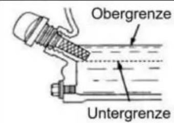
7.4 Bedienung
natural_image
Hand holding a mechanical component with a circular dial and adjustment knob (no text or symbols visible)natural_image
Diagram of a mechanical or electrical component with no visible text, numbers, or symbols
natural_image
Diagram of a mechanical component with a curved arrow indicating direction (no text or symbols)
natural_image
Illustration of a hand operating a mechanical device with a rotating wheel (no text or symbols visible)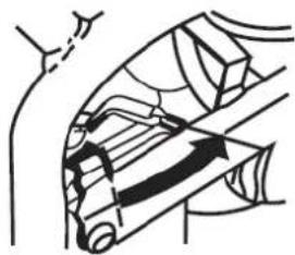
natural_image
Diagram of a mechanical or electrical component with directional arrows indicating motion (no text or symbols)natural_image
Diagram of a cable or cable support system with no visible text or symbolsnatural_image
Green industrial control panel with blue and white buttons, no visible text or symbols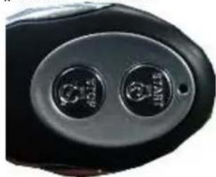
natural_image
Close-up of a black automotive head panel with two circular buttons (no visible text or symbols)natural_image
Close-up of a mechanical assembly with labeled parts (I and O), no readable text or symbols present.WARNUNG

natural_image
Cartoon illustration of a computer with a smiling face and a thought bubble showing a finger pointing at it (no text or symbols present)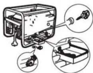
natural_image
Diagram of a robotic arm with a cloud and mechanical components, no text or symbols present

natural_image
Illustration of hands holding a small object with a pointer, enclosed in a circle (no text or symbols)
8.2 Transport
This manual contains information and important instructions for the installation and correct use of the ZIPPER generators ZI-STE2800; ZI-STE5500, ZI-STE8000 and ZI-STE8004.
Following the usual commercial name of the machine (see cover) is substituted in this manual with the name "machine".

This manual is part of the product and shall not be stored separately from the product. Save it for later reference and if you let other people use the product, add this instruction manual to the product.
Please read and obey the security instructions!
Due to constant advancements in product design, construction pictures and content may diverse slightly. However, if you discover any errors, inform us please.
Technical specifications are subject to changes!
Please check the product contents immediately after receipt for any eventual transport damage or missing parts.
Claims from transport damage or missing parts must be placed immediately after initial product receipt and unpacking before putting the product into operation.
Please understand that later claims cannot be accepted anymore.
Copyright
© 2018
This document is protected by international copyright law. Any unauthorized duplication, translation or use of pictures, illustrations or text of this manual will be pursued by law. Court of jurisdiction is the regional court Linz or the competent court for 4707 Schlüsslberg, Austria!
Customer service contact
This section contains information and important notices for safe commissioning and handling of machine.

For your own safety, read these operating instructions carefully before putting the machine into operation. This will enable you to handle the machine safely and prevent misunderstandings as well as possible damage to property and persons. Also observe the symbols and pictograms used as well as the safety instructions and hazard warnings!
12.1 Intended use of the machine
The machine is intended exclusively for the following activities:
This power unit is designed exclusively for operating electric devices whose max. performance is within the specifications for the generator. A higher starting current of inductive loads must be considered. The generator is designed to operate from conventional resistive and inductive loads, such as Lights, electric hand tools (drills, electric chain saws, compressors) determined.
When connecting to stationary systems such as heating, house supply, air conditioning or for the power supply of mobile homes, an electrician and the heating manufacturer must be consulted regarding the connection and grounding.
ZIPPER-MASCHINEN assumes no responsibility or warranty for any other use or use beyond this and for any resulting damage to property or injury.
12.1.1 Technical Restrictions
The machine is intended for use under the following ambient conditions:
Relative humidity: max. 65 %
Temperature (for operation) +5°C bis +40°C
Temperature (for storage and/or transport) -20irc C bis +55irc C
12.1.2 Prohibited Use / Forseeable Misuse
• Operation of the machine without adequate physical and mental aptitude
- Operating the machine without appropriate knowledge of the operating instructions (machine + motor).
• Changes in the design of the machine
- Operating the machine in wet and rainy conditions
- Operating the machine in a potentially explosive environment
- Operating the machine indoors or in closed areas
• Operation of the machine without functioning or missing guards
- Remove the safety markings attached to the machine.
- Modify, circumvent or disable the safety devices of the machine.
The prohibited/hazardous use or disregard of the information and instructions presented in this manual will result in the voiding of all warranty and damage claims against Zipper Maschinen GmbH.
12.2 User Requirements
The physical and mental suitability as well as knowledge and understanding of the operating instructions are prerequisites for operating the machine. Persons who, because of their physical, sensory or mental abilities or their inexperience or ignorance, are unable to operate the machinery safely must not use it without the supervision or instruction by a responsible person.
Please note that local laws and regulations may determine the minimum age of the operator and restrict the use of this machine!
Put on your personal protective equipment before working on the machine.
Work on electrical components or equipment may only be carried out by a qualified electrician or carried out under the guidance and supervision of a qualified Electrician.
12.3 Safety instructions
In order to avoid malfunctions, damage and health hazards when working with this machine, in addition to the general rules for safe working, the following measures in particular must be observed UNCONDITIONALLY:
- Check that the machine is in perfect condition before each use. Ensure that all guards are in place and working properly and that all nuts, bolts, etc. are securely tightened. Do not take the machine into operation if you notice that parts are missing or damaged!
- Ensure sufficient lighting conditions in the working and surrounding areas of the machine.
- Keep hands and feet away from moving machine parts and always ensure a safe stand when working.
- Ensure that the area to be tamped does not contain any electric cables, gas or water lines which could be damaged by vibration.
- Remove the adjustment tool from the machine before operation.
- Ensure that unauthorised persons maintain a safe distance from the machine and keep children away from the machine.
- The machine may only be operated, serviced or repaired by persons who are familiar with it and who have been informed of the dangers arising during this work.
• Always wear suitable personal protective equipment (eg. ear protection,..., etc.)! - Do not work with the machine if you are tired, not concentrated or under the influence of medication, alcohol or drugs!
- Never operate the unit in the presence of flammable liquids or gases (danger of explosion!).
- Carry out maintenance, adjustment and cleaning work only when the engine is switched off.
- Only use spare parts and accessories recommended by Zipper machines.
12.4 Special safety instructions for the operation of the machine
- Do not use the generator if it is raining, wet or has high humidity. RISK OF ELECTRIC SHOCK. DANGER OF LIFE!.
- Do not increase the regulated idle speed of the engine above 3,500 rpm. This could result in damage to the machine or personal injury.
12.5 Safety instructions for machines with combustion engine
- Do not touch the engine and/or muffler during operation or immediately after switching off! These areas become hot during operation and can cause burns.
- Do not touch the spark plug connector when the engine is running (electric shock!).
- Do not operate the unit in closed areas or in poorly ventilated rooms unless there is adequate ventilation through exhaust fans or hoses. (Risk of suffocation from carbon monoxide!)
- Do not smoke while the machine is in operation.
- Do not smoke when refuelling the machine.
- Refuel the machine only in a well ventilated area.
- Do not refuel the machine when the engine is running or the machine is still hot.
- Do not refuel the machine near naked flames.
- Do not spill fuel when refuelling.
- Do not crank a gas flooded engine as long as the spark plug is removed- fuel in the cylinder sprays out of the spark plug opening.
- Do not carry out an ignition spark test on engines if the engine is flooded or gas can be smelled. A stray spark could ignite the vapours.
- Do not use fuel to clean machine parts, especially indoors. Vapours from fuels may explode.
- Always keep the area around the muffler free of foreign substances such as leaves, paper, cardboard, etc. A hot muffler could ignite these substances and cause a fire.
- Close the filler cap after refuelling.
- Check the fuel line and tank regularly for leaks and cracks. Do not operate the machine if leaks in the fuel system are known.
- Store fuel only in designated and approved containers.
12.6 Hazard warnings
Despite intended use, certain residual risks remain. Due to the design and construction of the machine, hazardous situations may occur which are identified as follows in these operating instructions:
DANGER

A safety instruction designed in this way indicates an imminently hazardous situation which, if not avoided, will result in death or serious injury.
WARNING

Such a safety instruction indicates a potentially hazardous situation which, if not avoided, may result in serious injury or even death.
CAUTION

A safety instruction designed in this way indicates a potentially hazardous situation which, if not avoided, may result in minor or moderate injury.
NOTICE

A safety note designed in this way indicates a potentially dangerous situation which, if not avoided, may result in property damage.
Irrespective of all safety regulations, their sound common sense and corresponding technical suitability/training are and remain the most important safety factor in the error-free operation of the machine. Safe working depends first and foremost on you!
13 ASSEMBLY
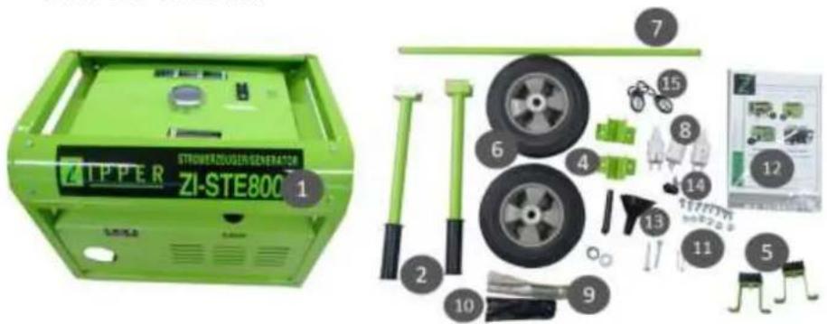
13.1 Check scope of delivery
After delivery, check the machine immediately for transport damage and missing Parts.
13.2 Assembly
13.2.1 ZI-STE2800
| 1. Wheels assembly | 2. Handle assembly |
| 3. Assembly rubber feet |
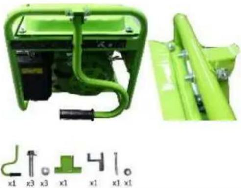
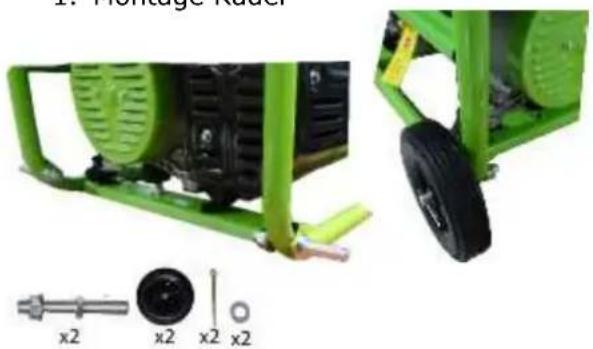
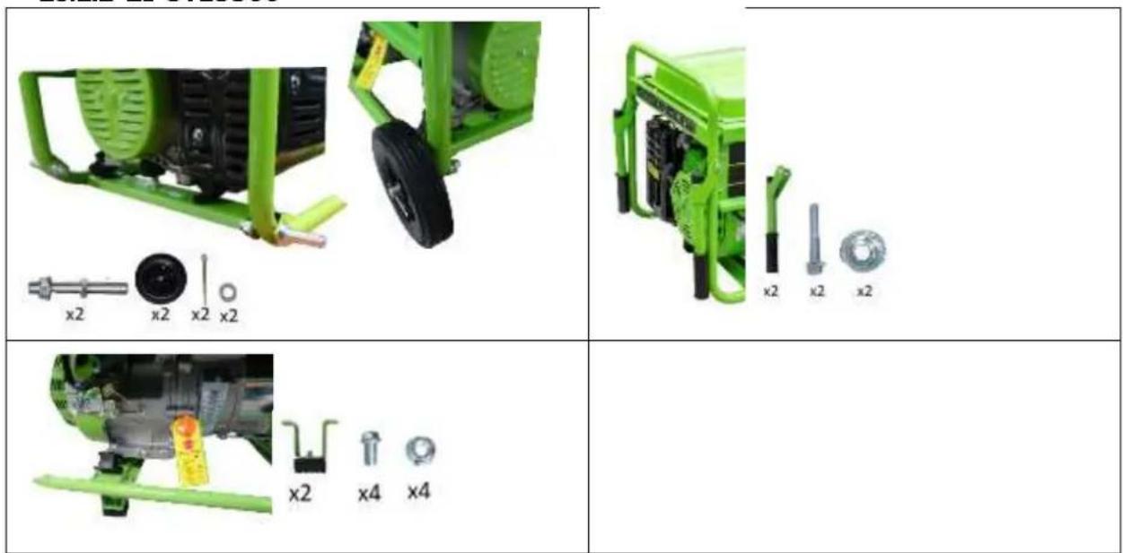
13.2.2 ZI-STE5500
1. Wheels assembly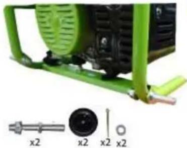  | 2. Handle assembly |
3. Assembly rubber feet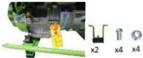 |
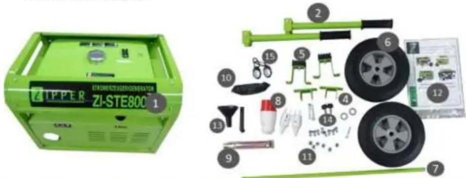
13.2.3 ZI-STE8000 / ZI-STE8004
5. Wheels assembly | 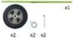 | 6. Handle assemblyFix the bracket to the frame using screws and nuts and then mount the handle in the bracket using bolts. |
7. Assembly rubber feet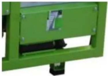 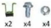 |
- Battery assembly

natural_image
Close-up of a green industrial electrical enclosure with blue components and internal wiring (no visible text or symbols)Loosen the protective cover to get access to the battery.
- Mount the poles to the battery with screws, washers and nuts.
- Connect the red cable to the positive (+) terminal of the battery.
- The black cable is connected to the negative pole (-) of the battery.
- Disconnect and connect the battery in reverse order.
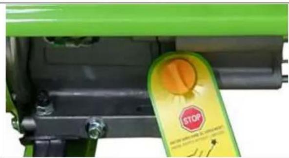
13.3 Checklist before each use
13.3.1 Checking the engine oil level
NOTICE

Too low an oil level will damage the engine and shorten the life of the machine. Therefore, check the engine oil level before every start and top up the engine oil if necessary.
natural_image
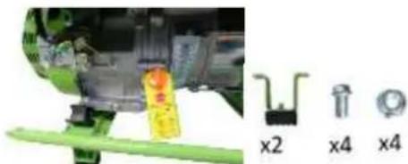
Close-up of a green industrial machine component with a yellow stop tag (no visible text or symbols)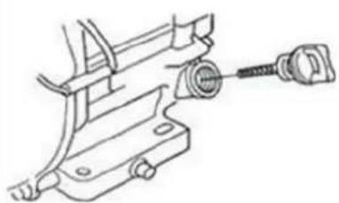
natural_image
Technical line drawing of a mechanical clamp or bracket assembly (no text or symbols)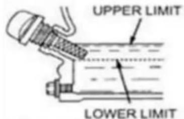
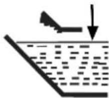
- To check the engine oil level, place the machine on a safe, level surface. Switch off the engine and allow the machine to stand for ten minutes so that the circulating oil can collect in the oil pan.
- Unscrew the oil dipstick and wipe with a clean, lint-free cloth or a non-fibrous paper towel.
- Push the dipstick into the opening, but do not screw it in. (Make sure that the dipstick has really been pushed in completely).
- Pull out the oil dipstick again and read off the oil level. There are two markings for this - see illustration on the left.
- If the oil level is low, refill the recommended oil up to the upper edge
- Push in the oil dipstick again and tighten.
13.3.2 Checking the fuel tank level
NOTICE

Observe the safety regulations for fuel control. Filter the fuel during refuelling to prevent foreign particles from entering the combustion chamber. Wipe up leaked fuel.
- Screw on the tank cap (sits on the fuel tank).
- Level check in the form of a visual inspection or via display. If necessary, top up with fuel with the appropriate octane number (RON 95).
- Close the fuel filler cap tightly after refuelling.
14 OPERATION
14.1 Information on Initial Start-up
NOT ICE

Note that the machine is delivered without engine oil and fuel. Make sure that this equipment is filled up before the machine is put into operation for the first time. ATTENTION: The machine does not start until the engine oil has been refilled to the upper limit.
14.1.1 Grounding
Before putting the machine into operation, have a grounding system installed by a qualified electrician!
Exact grounding instructions for portable generators depend on the jurisdiction of the country in which the generator is commissioned. Please observe them exactly.
14.1.2 Test Run Initial Start-up
- Let the machine run idle for about 3 minutes.
- Pay attention to abnormal noises.
- Pay attention to the exhaust fumes (too black, too white)?
14.1.3 Notes on the first 20 operating hours
In order to optimize the life expectancy of your machine, the following points should be observed:
- Do not operate the engine for the first 20 operating hours @ maximum load (this also applies to used engines after extensive maintenance). This means lower speed and lower maximum working load than during normal operation.
- Change the engine oil after the first 20 hours of operation.
14.2 Operating Instructions
14.2.1 Integration into an existing electricity grid
This machine is designed exclusively for the operation of electrical devices whose maximum power lies within the power specifications of the generator. A higher starting current from inductive loads must be taken into account. The generator is designed for the operation of conventional ohmic and inductive loads such as light chains, electric hand tools (drilling machines, electric chain saws, compressors).
When connecting to stationary systems such as heating, house supply, air conditioning or for the power supply of mobile homes, an electrician and the heating manufacturer must be consulted regarding connection and grounding.
14.2.2 Devices are connected to the AC terminals
- Before connecting a device on the AC socket you must control the perfect condition of the device. - When you recognize that a connected device acts unusual you must stop the generator and disconnect the device. Control whether the device is damaged or if the generator was overloaded by the device.
ATTENTION: A short exceed of the normed power capacity of the generator is possible but if this happens oftener the life time of the generator will be shortened.
Please consider: Some devices, for instance cooling devices need up to 5 times more starting current than current during the operation.
14.2.3 Operation of the generator to over 1800m above sea level
- When is operating at high altitudes is due to the lower oxygen content in the air, the air / fuel mixture too dense. This leads to loss of power, increased fuel consumption and the rapid deterioration of the spark plugs and heavy start the engine.
- the generator is designed to operate at high altitudes, you should modify the carburetor in a certified service center. Nevertheless, it is a power drop of 3.5% per 300m altitudes to take slope into account.
CAUTION: The operation of the generator with a modified carburetor at low altitude leads to overheating of the engine.
14.3 AC Operation
Connect the devices to the AC socket. The most devices need more power for starting than declared. A device with a rated power (1500kW) can temporarily load your generator (eg ZI-STE2800) to its maximum when switched on.
Always connect the devices in a falling chronology of their kW-consumption!
When the generator is overloaded the power supply gets interrupted. So turn off the generator and study the problem.

14.4 Operation
14.4.1 Start (for ZI-STE2800 and ZI-STE5500)
To start the generator, proceed as follows:
- Ensure that the generator is in a perfect condition.
- When there are some devices connected with the AC sockets you have to disconnect them.
- Open the fuel tap.
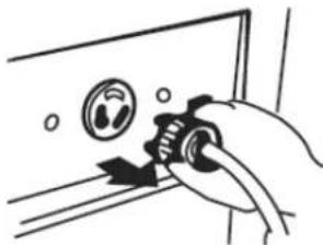
- During a cold start close the choke lever, a warm start Choke open (ie engine warm, eg by lower operating break)
- Turn ON the engine switch.
- Start the machine by pulling the starter handle.
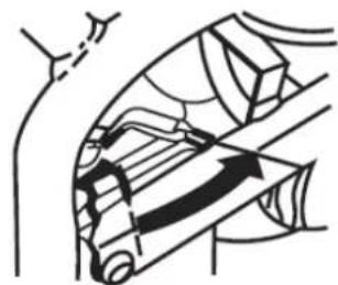
- If the choke lever is still closed, open it after a short warm-up phase. (refer to the illustration)
natural_image
Hand using a tool to adjust or install a wall-mounted device (no text or symbols visible)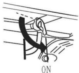
natural_image
Diagram of a person using a tool to lift or lift an object, labeled 'ON' at the bottom (no other text or symbols)

natural_image
Illustration of a hand turning a mechanical component with a circular component (no text or symbols)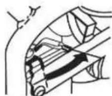
natural_image
Diagram of a mechanical or electrical component with no visible text, numbers, or symbols14.4.2 Start (for ZI-STE8000 and ZI-STE8004)
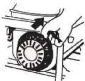
To start the generator, proceed as follows:
- Ensure that the generator is in a perfect condition.
- When there are some devices connected with the AC sockets you have to disconnect them.
- Open the fuel tap.
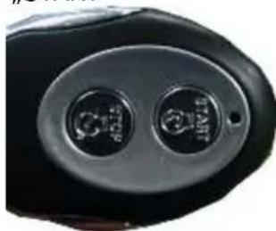
- Starting the generator with the remote control or with the start key
Key: Turn the key to the „START“ position.
natural_image
Green industrial control panel with blue and black buttons, no visible text or symbolsRemote control Press the „START“ button

natural_image
Close-up of a black electronic device with two circular buttons (no visible text or symbols)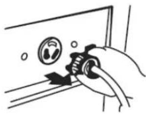
natural_image
Hand holding a mechanical component with a circular dial and arrow, no visible text or symbols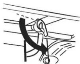
natural_image
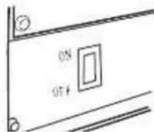
Diagram of a mechanical or electrical component with curved lines and a hanging hook (no text or symbols)ON
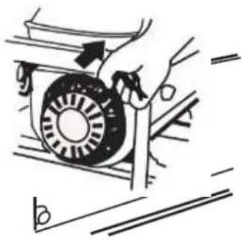
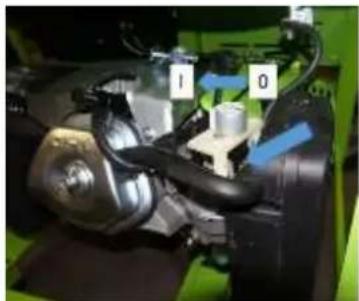
Only in an emergency (insufficient battery load), the generator can also be started by recoil starter. To do so: The throttle valve must be operated manually (= choke), for starting close the throttle valve (position 0) after start open the throttle valve again (position I). It is necessary to disassemble the side guard.
Disassemble the side guard

natural_image
Close-up of a mechanical assembly with labeled parts (1 and 0), no readable text or symbols present.Throttle valve to position 0 for starting. To Pos. I during operation.
14.4.3 Stop
- Turn off connected equipment and disconnect from the socket.
• To turn off the generator, move the power switch simply to the OFF position. - Close the fuel tap.
15 MAINTENANCE
WARNING:
Lack of maintenance or improper maintenance and repair before using the appliance can result in serious injury or death! Take therefore the safety rules, operating and maintenance instructions very seriously.
Repairs only by qualified staff!
WARNING

Hot surfaces and rotating machine parts while the engine is running can cause serious injury or even death. Always stop the machine before carrying out any conversion, adjustment, cleaning or maintenance work and secure it against unintentional restarting.
15.1 Maintenance plan
| (1) Interval can vary according to the air quality(2) Only by specialists! | Prior to each start | (for new machine) after first Month or 20 operation hours | Every 3 months or every 50 operation hours | Every 6 months or every 100 operation hours | Every 2 years or every 300 operation hours | |
| Engine oil | Controll of the level | X | ||||
| Changing | X | X | ||||
| Air filter | Controlling | X | ||||
| Changing | X (1) | |||||
| Spark plug | Control | X | ||||
| Change | X | |||||
| Valve clearance | Control, adjustment | X(2) | ||||
| Fuel tank and fuel tank filter | Clean | Yearly (2) | ||||
| Fuel pipe | Control | Every 2 years (2) | ||||
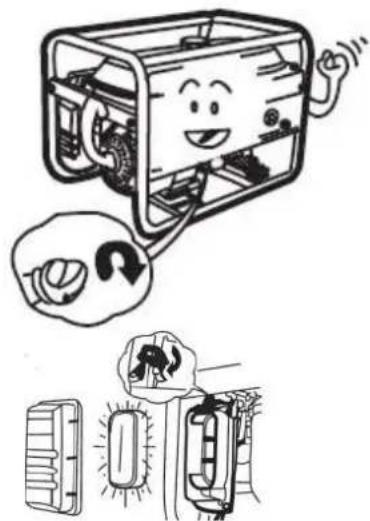
15.1.1 Changing the engine oil
Change the oil when it's still warm from the operation. Ensure that the engine switch in the OFF position.
- Turn the switch to the OFF position, if set to ON.
- Unscrew the fixing screw of the side cover off, remove the cover. Unscrew the oil filler cap.
- Tilt the machine and let the oil flow into a box.

natural_image
Cartoon illustration of a smiling computer with hands operating it, accompanied by a thought bubble showing a finger pointing at it (no text or symbols present)
- Refill new engine oil to the lower edge of the oil filler neck.
ATTENTION: Dispose the old oil PROPERLY!!! Pour it into a leak proofed box and bring it to a recycling center.
- Screw back the screw cap on the oil filler neck.
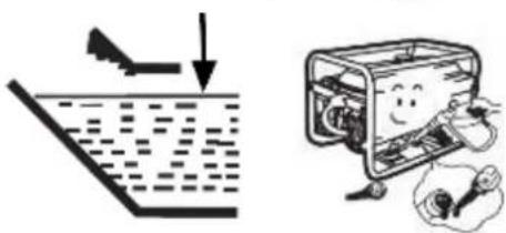
15.1.2 Air filter
- Remove the cover of the air filter.
• Take out the air filter. - Clean it with water.
- Wring it out.
- Let the air filter become saturated with engine oil.
- Wring out the air filter.
Mount the air filter again.
- Insert air filter
- Replace the cover
- Secure snap closure
natural_image
Simple line drawing of a boat leaping over water with an arrow indicating downward motion (no text or symbols)
natural_image
Illustration of a smiling computer with hands operating the case and a close-up of a device inside (no text or symbols)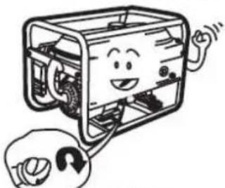
natural_image
Cartoon illustration of a smiling device with hands holding a wrench (no text or symbols)
natural_image
Illustration of a vehicle's front bumper and rear bumper with a thought bubble showing a warning sign (no text or symbols present)
ATTENTION: NEVER OPERATE THE MACHINE WITHOUT OR A NOT MAINTAINED AIR FILTER!!!
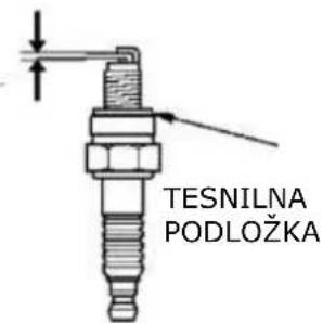
15.1.3 Spark plug
- Remove the spark plug cap
- Screw out the spark plug.
- Optical Control: When the electrodes are batteredamaged – change the spark plug!
- Clean the spark plug.
- Control the distance between the two electrodes: 0,6 - 0,7 mm!

natural_image
Diagram of a bicycle undercarriage with a cloud above, showing mechanical components and motion lines (no text or symbols)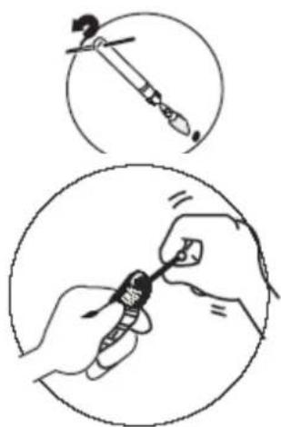
natural_image
Illustration showing two steps of a hand holding a small object, with no visible text or symbols.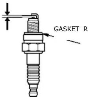
- The gasket ring should be in a good condition.
- When the spark plug gets changed you must screw it in with your hands. When you can't turn it any more you have to use the spark plug wrench to fasten it with half an round.
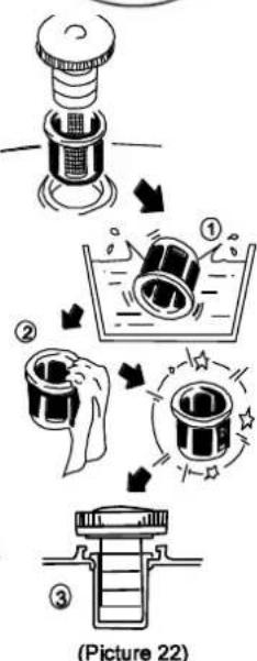
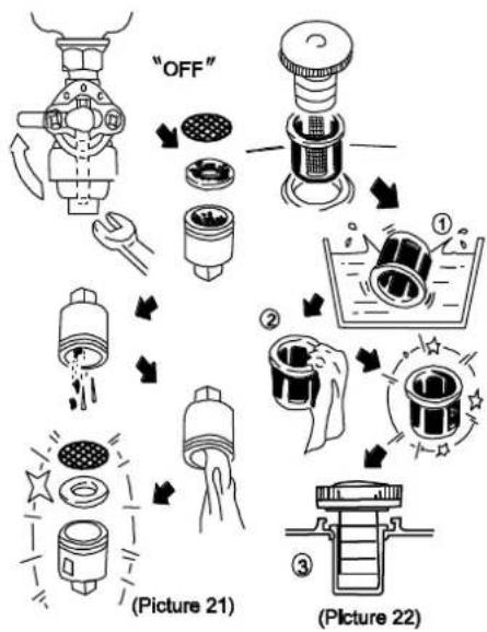
15.1.4 Fuel Tank & Filter Valve (every 150 hours)
- fuel cock lever to "OFF"
• In solution (with mild detergent) - clean all parts.
- Put back together.
- Remove the engine tank filter
- In solution, clean (with mild detergent).
- Replanting.
0.7 - 0.8mm

flowchart
graph TD
    A["OFF"] --> B["Liquid Washing"]
    B --> C["Water Washing"]
    C --> D["Cleaning"]
    D --> E["(Picture 21)"]
    E --> F["Recycling"]
    F --> G["(Picture 22)"]
15.2 Transport
- Let the machine get cold for 15 minutes.
- Do not lay the machine on the side during the transport. Oil or fuel leakage.
- Do not lay heavy or wet things onto the generator during transportation.
15.3 Storage
If the machine is not used for a longer period of time (>30 days):
- Empty the oil tanks or fuel tank.
- Remove the spark plug and pour a few drops of engine oil into the cylinder. Using a rope starter, turn the engine a few times so that the oil is well distributed inside the cylinder. Clean the spark plug and replace it.
- Cover the cooled machine and store it out of the reach of children and unauthorised persons in a well-ventilated, dry and frost-free environment.
16 DISPOSAL

Do not dispose of your machine in residual waste. Contact your local authorities for information on available disposal options. If you buy a new vibratory plate or equivalent from your dealer, he is obliged in certain countries to dispose of your old machine properly.
17 TROUBLESHOOTING
WARNING

Hot surfaces and rotating machine parts while the engine is running can cause serious injury or even death. Always stop the machine before carrying out troubleshooting work and secure it against unintentional restarting.
| Trouble | Reason | Shooting |
| The engine doesn't start | No fuelTurn engine switch to ONReversing defectiveCheck oil levelSpark plugs contact CandleAir filter cloggedFuel tap cloggedFaulty motor | Filling the fuel tankswitch to ONrepair recoiladd oilOIL LEVEL CONTROL!Check for real game 16.2.3See Maintenance 16.2.2refer to Maintenancerefer to MaintenanceContact the retailer |
| Engine is difficult to start or runs bad | Too rich fuel mixtureCarburetor incorrectlyFaulty spark plug, dirty or misaligned | Set choke to OPEN positionCan make settings by authorized personnelClean the spark plug, New Adjust or replace |
| Motor is too hot | Too little engine oilCold air system restrictedDirty air filterCarburetor not adjusted properly | Engine oilClean fan guard, internalClean the cooling finsClean the air filterLet carburetor adjusted by authorized specialist |
| Motor too little power | Dirty air filter | Clean the filter elements, possibly exchange |
| No power from the power outlets | Breaker is in position "OFF"Engine speed is too low | Breaker to position "ON"Let engine speed of an authorized service set |
| Low output voltage under load | Too much load available | Reduce Existing Load |
| Uneven Output voltage | Unbalanced load available | Total load away. Then apply again individually to determine what causes the uneven loads the function. |
| Digital display "P-25" | P-25: Request to first oil change when a new device after 25 operating hours | Change Engine Oil |
| Digital display "P-50" | P-50: Request to Change oil and clean the air filter every 50 operating hours | Change the engine oilClean the air filter |
| Digital display "P-100" | P-100: Request for cleaning the fuel and air filter and oil change every 100 operating hours | Clean the fuel filterClean the air filterChange the engine oil. |
18 PREFACIO (ES)
20.2.2 ZI-STE5500
| x2 x2 x2 x2 | x2 x2 x2 |
| x2 x4 x4 |
20.2.3 ZI-STE8000 / ZI-STE8004
21.4 Funcionamiento
21.4.1 Encendido / Arranque (ZI-STE2800 y ZI-STE5500)
natural_image
Diagram of a hand operating a mechanical device with a rotating wheel (no text or symbols visible)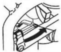
natural_image
Diagram of a mechanical or structural component with no visible text, numbers, or symbols21.4.2 Encendido / Arranque (ZI-STE8004 y ZI-STE8004)
natural_image
Hand holding a valve on a door panel, no text or symbols visible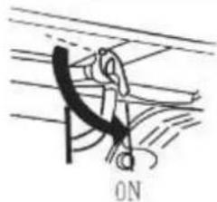
natural_image
Simple line drawing of a person climbing a rope, no text or symbols presentnatural_image
Green industrial control panel with blue and digital buttons (no visible text or symbols)„START“

natural_image
Close-up of a black electronic device with two circular buttons (no visible text or symbols)natural_image
Close-up of a mechanical assembly with labeled parts (1 and 0), no readable text or symbols beyond labelsPos. 0 Encendido.
natural_image
Cartoon illustration of a smiling computer with hands and legs, accompanied by a thought bubble showing a finger pointing at it (no text or symbols present)natural_image
Simple line drawing of a boat launching from a floating platform (no text or symbols)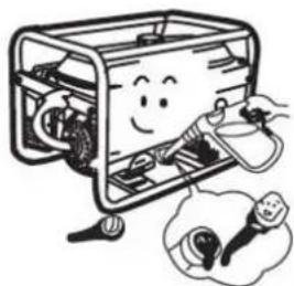
natural_image
Cartoon illustration of a smiling computer box with hands operating it, next to a small lamp and plug (no text or symbols)natural_image
Diagram of a robotic arm with sensors and a cloud-like object above it, no text or symbols present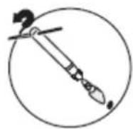

0,6 -0,7MM
ARANDELA DE SELLADO

28.2.2 ZI-STE5500
28.2.3 ZI-STE8000 / ZI-STE8004
natural_image
Close-up of a green industrial machine component with a yellow stop tag (no visible text or symbols)29.4 Fonctionnement
natural_image
Hand holding a valve with a circular dial indicator (no text or symbols visible)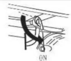
natural_image
Simple line drawing of a rope or cable being lifted by a hook, with no text or symbols present.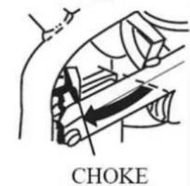

natural_image
Hand holding a mechanical component with a circular dial and arrow indicator (no text or symbols)
natural_image
Diagram of a mechanical or structural component with no visible text, numbers, or symbols29.4.2 Allumage / Démarrage (ZI-STE8000; ZI-STE8004)
natural_image
Simple line drawing of a person climbing a rope with a curved arm, labeled 'ON' at the bottom (no text or symbols on the diagram itself)natural_image
Green industrial control box with blue buttons and a digital display (no visible text or symbols)„START“
natural_image
Close-up of a black electronic device with two circular buttons (no visible text or symbols)natural_image
Close-up of a mechanical assembly with blue arrows indicating components (no visible text or symbols)Pos. 0 Encendido.
natural_image
Cartoon illustration of a computer with a smiling face and a thought bubble showing a finger (no text or symbols)natural_image
Simple line drawing of a boat leaping over water with an arrow indicating downward motion (no text or symbols)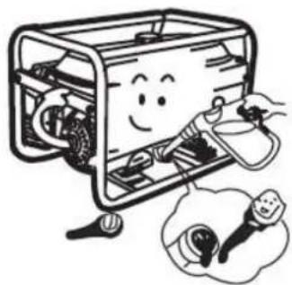
natural_image
Cartoon illustration of a smiling device inside a box with hands connecting it, accompanied by an inset showing a small lamp (no text or symbols present)AVERTISSEMENT: N'UTILISEZ JAMAIS LA MACHINE SANS FILTRE À AIR OU AVEC UN FILTRE SANS ENTRETIEN!
30.1.3 Bougie
natural_image
Diagram of a mechanical device with gears and a cloud, no text or symbols present
natural_image
Illustration of hands using a tool to apply or install a small object (no text or symbols present)
0.7 - 0.8mm

36.2.2 ZI-STE5500

36.2.3 ZI-STE8000 / ZI-STE8004
37.3 Obsluha
37.3.1 Zapnutie / Štart (ZI-STE2800; ZI-STE5500)
natural_image
Hand holding a mechanical component on a door panel (no text or symbols visible)natural_image
Diagram of a hand holding a curved object with motion lines, labeled 'ON' at the bottom (no other text or symbols)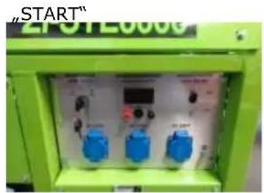
natural_image
Green industrial electrical control box with blue buttons and a digital display (no readable text or symbols)


natural_image
Close-up of a mechanical assembly with blue arrows indicating parts (no visible text or symbols)Pos. 0 Zapnutie.
Pos. I Obsluha
15.3.2 Vypnutie
natural_image
Cartoon illustration of a computer with a smiling face and a thought bubble containing a small object (no text or symbols)
natural_image
Illustration showing a downward arrow and a cartoon-style container with a smiling face, next to a hand holding a tool (no text or symbols)
natural_image
Diagram showing a vehicle's front compartment with a thought bubble depicting a person in motion (no text or symbols present)
POZOR: STROJ NIKDY NEPREVÁDZKUJTE BEZ VZDUCHOVÉHO FILTRA ALEBO S NEUDRŽOVANÝM FILTROM!!!
38.1.4 Zapal'ovacia sviečka
natural_image
Diagram of a mechanical device with cloud and gear components, plus a magnified view of a tool (no text or symbols)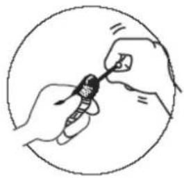
natural_image
Illustration of hands holding a small object inside a circular frame (no text or symbols)natural_image
Technical line drawing of a spark plug with threaded shaft and mounting bracket (no text or symbols)44.2.2 ZI-STE5500
| x2 x2 x2 x2 | x2 x2 x2 |
| x2 x4 x4 |
44.2.3 ZI-STE8000 / ZI-STE8004
45.3 Obsluha
45.3.1 Zapnutí / Start (ZI-STE2800; ZI-STE5500)
natural_image
Illustration of a vehicle's front bumper and rear bumper with a sunburst effect (no text or symbols)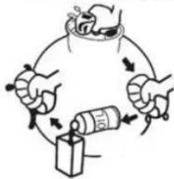
POZOR: STROJ NIKDY NEPROVOZUJTE BEZ VZDUCHOVÉHO FILTRU NEBO S NEUDRŽOVANÝM FILTREM!
52.2.2 ZI-STE5500

52.2.3 ZI-STE8000 / ZI-STE8004
natural_image
Close-up of a green tractor's wheel and black frame with a yellow stop tag (no visible text or symbols)
natural_image
Technical line drawing of a mechanical clamp or bracket assembly (no text or symbols)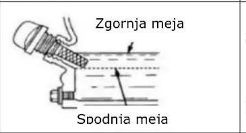
53.4 Rokovanje
53.4.1 Vklop / zagon (ZI-STE2800/ZI-STE5500)
CHOKE
• Stikalo za vklop dajte na ON
natural_image
Hand operating a mechanical component with a rotating wheel and lever (no text or symbols visible)natural_image
Green industrial control panel with blue buttons and a digital display (no readable text or symbols)V sili (brez baterije)
natural_image
Diagram of a mechanical or anatomical structure with no visible text, numbers, or symbols
natural_image
Hand holding a device with a circular dial and plug, no text or symbols visible
natural_image
Diagram of a mechanical or electrical component with no visible text or symbols

natural_image
Close-up of a mechanical assembly with labeled parts (1 and 0), no readable text or symbols beyond labelsPos. 0 Vklop. Pos. I Rokovanje
- Vlijte novo motorno olje do spodnjega roba polnilnega nastavka za olje.
natural_image
Simple line drawing of a boat leaping over water with an arrow indicating downward motion (no text or symbols)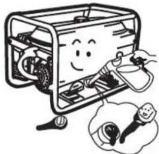
natural_image
Illustration of a smiling computer with hands operating the case and a thought bubble showing a plug (no text or symbols)POZOR! Staro olje STROKOVNO odstranite!!! Ujemite ga v dobro zatesnjeno posodo in ga odnesite v najbližji reciklažni center.
natural_image
Cartoon illustration of a smiling rectangular device with wheels and a magnifying glass, no text or symbols present.- Ponovno privijte pokrov z navojem na polnilni nastavek za olje.
54.1.3 Zračni filter
natural_image
Illustration of a vehicle's front and rear compartments with a thought bubble showing a car (no text or symbols present)- Ožmite ga
- Pustite, da do konca vsrka motorno olje
- Nato filter ožmite, da odteče odvečno olje
- Ponovno vstavite zračni filter
- Ponovno namestite pokrov
• Fiksimajte zaskočno zapiralo

POZOR! STROJ NE SME NIKOLI OBRATOVATI BREZ ZRAČNEGA FILTRA OZ. Z NEVZDRŽEVANIM ZRAČNIM FILTROM.
54.1.4 Svečka
• Odstranite kapico svečke
natural_image
Diagram of a robotic arm with a cloud and mechanical components, no text or symbols present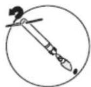

natural_image
Illustration of hands using a handheld device to interact with a small electronic component (no text or symbols visible)0,6 -0,7MM
0.7 - 0.8mm
60.2.2 ZI-STE5500
| x2 x2 x2 x2 | x2 x2 x2 |
| x2 x4 x4 |
60.2.3 ZI-STE8000 / ZI-STE8004
 |  |
 | |
| Postavljanje akumulatora | |
 | |
| Za postavljanje akumulatora, učinite sljedeće:Instalirajte akumulator pomoću vijaka, podložaka i matica.Priključite crvenu žicu na pozitivni (+) pol na akumulatoru.Postavite crni kabel za uzemljenje na negativni (-) pol na akumulatoru.Isključite akumulator obrnutim poretkom. | |
61.4 RAD
61.4.1 Uključivanje (ZI-STE2800; ZI-STE5500)
Kod uključivanja generatora, postupite na sljedeći način:
- Provjerite je li generator u savršenom stanju.
- Ukoliko su neki uređaji uključeni u utičnicu, isključite ih.
- Otvorite slavinu za gorivo.
- Kod hladnog paljenje morate zatvoriti čok, a za toplo paljenje ga otvorite.
- izvucite čok.
• Uključite sklopku motora na ON.

natural_image
Hand holding a mechanical knob on a door panel (no text or symbols visible)
natural_image
Simple line drawing of a mechanical or electrical component with no visible text, numbers, or symbols.
CHOKE
- Uključite stroj tako da povučete startnu ručku.
- Kada je čok zatvoren, morate ga otvoriti, ako je motor topao od rada.
- Ponovno umetnite čok.

natural_image
Hand operating a mechanical component with a circular dial and arrow indicator (no text or symbols)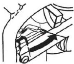
natural_image
Diagram of a mechanical or anatomical structure with curved and straight lines, no visible text or symbols61.4.2 Uključivanje (ZI-STE8000; ZI-STE8004)
Kod uključivanja generatora, postupite na sljedeći način:
• Provjerite je li generator u savršenom stanju.
- Ukoliko su neki uređaji uključeni u utičnicu, isključite ih.
- Otvorite slavinu za gorivo.

natural_image
Hand operating a door switch with a rotary knob (no text or symbols visible)
natural_image
Simple line drawing of a mechanical or electrical component with no visible text, numbers, or symbols.ON

natural_image
Green industrial electrical switchgear with blue and red buttons (no visible text or symbols)U hitnim slučajevima (bez baterije)

natural_image
Close-up of a mechanical assembly with blue arrows indicating components (no visible text or symbols)Pos. 0 Paljenje.
Pos. I Rad
61.4.3 Isključivanje/gašenje motora
- Prije isključivanja/gašenja stroja, isključite sve uređaje priključene na generator.
- Úgasite generator tako da glavnu sklopku motora stavite u položaj OFF.
• Zatvorite slavinu za gorivo.
62 ODRŽAVANJE
UPOZORE N JE

natural_image
Cartoon illustration of a smiling computer with a thought bubble showing a finger pointing at it (no text or symbols present)- Odvrnite zatezni vijak postraničnog poklopca te uklonite poklopac. Odvrnite poklopac spremnika za ulijevanje ulja.
- Nagnite generator i ispustite ulje u za to predviđenu nepropusnu posudu.
- Ulijte svježe ulje do donje oznake na nastavku spremnika za ulje.

natural_image
Simple line drawing of a boat leaping over water with an arrow indicating downward motion (no text or symbols)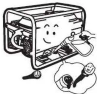
natural_image
Cartoon illustration of a smiling computer case with hands holding a tool, accompanied by a thought bubble showing a small light bulb (no text or symbols)POZOR: Staro ulje zbrinite na EKOLOŠKI PRIHVATLJIV način! Čuvajte ga u dobro zatvorenoj posudi i donesite ga u Vama najbliži centar za recikliranje.
- Zavrnite vijak na nastavku spremnika za ulijevanje ulja.
natural_image
Illustration of a smiling portable device with attached circuit board and electrical components, accompanied by a close-up of its internal components (no text or symbols present)8.2.2 Filtar zraka
- Skinite poklopac za filtar zraka.
- Izvadite filtar zraka.
• Operite ga u vodi.
- Iscijedite ga.
• Filtar natopite motornim uljem.
natural_image
Illustration of hands performing a medical procedure with a bottle and container (no text or symbols)OPREZ: NIKADA NE RADITE SA STROJEM BEZ FILTRA ILI FILTRA KOJI SE NE ODRŽAVA.
8.2.3 Svjećica
ZI-STE5500
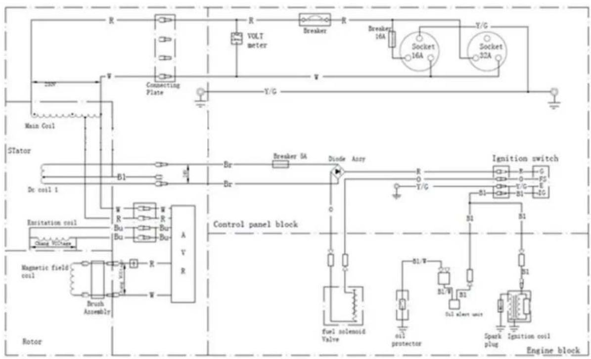
flowchart
graph TD
    A["Main Coil"] --> B["Stator"]
    B --> C["Dr coil 1"]
    C --> D["Magnetic field coil"]
    D --> E["Brush Assembly"]
    E --> F["Control panel block"]
    F --> G["Ignition switch"]
    G --> H["Engine block"]

    subgraph Control Panel Block
        I["Br"] --> J["Breaker 5A"]
        K["Br"] --> L["Breaker"]
        M["Diode Ancy"] --> N["R"]
        O["Y/G"] --> P["R"]
        Q["B1"] --> R["Switch 16A"]
        S["B1"] --> T["Switch 32A"]
    end

    subgraph Engine Block
        U["fuel solenoid Valve"] --> V["Oil protector"]
        W["Oil alert unit"] --> X["B1"]
        Y["Spark plug"] --> Z["B1"]
        AA["Ignition coil"] --> AB["B1"]
        AC["Engine block"] --> AD["Motor"]
    end

    style Control Panel Block fill:#f9f,stroke:#333
    style Engine Block fill:#ccf,stroke:#333
Ignition switch connecting
| Sl | Black | P | Pink |
| O | Orange | Br/W | Brown Red |
| Bu | Blue | LB | Light blue |
| Gr | Gray | V/G | Yellow/Green |
| R | Red | W | White |
| B1 | Black | F | Pink |
| 0 | Orange | Red | Brown/Red |
| Bu | Blue | LB | Light blue |
| Gr | Gray | I/O | Yellow/Green |
| X | Red | y | White |
Ignition switch connecting
| IG | E | EAT | ST | FS | G | |
| OFF | ||||||
| ON | ||||||
| Start |
2
ZI-STE8004

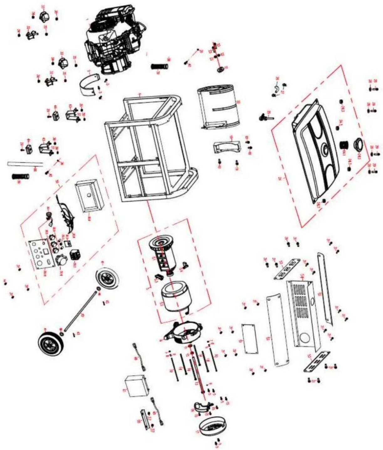
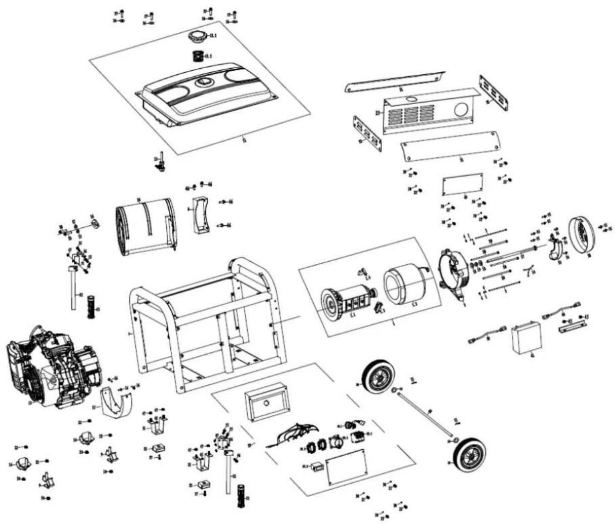
67 ERSATZTEILE / SPARE PARTS
(EN) With ZIPPER spare parts you use spare parts that are ideally matched to each other. The fitting accuracy of the parts shortens their installation time and increases the service life of the machine.
NO TE
The installation of parts other than original spare parts leads to the loss of the guarantee! Therefore, when replacing components/parts, only use original spare parts! When ordering spare parts, please use the service form at the end of this manual. Always state machine type, spare part number and designation. In order to avoid misunderstandings, we recommend enclosing a copy of the spare part drawing with the spare part order, on which the required spare parts are clearly marked.
You will find the ordering address under customer service addresses in the foreword to this documentation.
| Nr. | BESCHREIBUNG / DESCRIPTION | Stk | Nr. | BESCHREIBUNG / DESCRIPTION | Stk. |
| 1 | Engine | 1 | 20 | Motor assembly | 4 |
| 2 | Bracket, air cleaner | 1 | 20.1 | Rotator | 1 |
| 3 | Isolator A | 2 | 20.2 | Stator | 1 |
| 4 | Isolator B | 2 | 20.3 | Carbon brush comp | 1 |
| 5 | Dustproof sheet | 1 | 20.4 | Grouding post comp | 1 |
| 6 | Frame | 1 | 21 | Foot shaft | 2 |
| 7 | T-foot support | 2 | 22 | Cotter | 2 |
| 8 | T-shaped foot support cushioning seat | 2 | 23 | Casters | 2 |
| 9 | Handle sleeve | 1 | 24 | Motor bracket | 1 |
| 10 | Curved handle | 1 | 25 | Bolt M8x1x210 | 1 |
| 11 | Handle fixed Card | 1 | 26 | Bolt M6x160/GB5798 | 4 |
| 12 | Pane1 comp | 1 | 27 | Automatic Voltage Regulator | 2 |
| 12.1 | Rocker switch | 1 | 28 | End Cover, Generator | 1 |
| 12.2 | Voltmeter | 1 | 29 | Nut M8/GB6177 | 4 |
| 12.3 | DC-Terminal | 1 | 30 | Bolt M6x12/GB5787 | 6 |
| 12.4 | Continental socket | 2 | 31 | Bolt M6x40/GB5787 | 4 |
| 12.5 | Breaker | 1 | 32 | Nut M6/GB6177 | 5 |
| 13 | Muffler Comp | 1 | 33 | Nut M8/GB6177 | 3 |
| 14 | Packing exhaust | 1 | 34 | Bolt M8x40/GB5787 | 3 |
| 15 | Shells pad 8/GBT93 | 3 | 35 | Bolt M6x55/GB5787 | 1 |
| 16 | Nut M8/GB6170 | 6 | 36 | Bolt M8x16/GB5787 | 2 |
| 17 | Muffler support | 1 | 37 | Nut M12x1.25/GB6177 | 2 |
| 18 | Fuel cock | 1 | 38 | Flat pad ∅8x∅24x1.5 | 1 |
| 19 | Fuel Tank assembly | 1 | 39 | Bolt M5x16/GB5789 | 5 |
| 19.1 | Fuel Filter | 1 | 40 | Bolt M5x12/GB5789 | 3 |
| 19.2 | Tank cover gasket | 1 | 41 | Flat pad ∅6x∅22x2 | 4 |
| 19.3 | Fuel tank cap comp | 1 | 42 | Bolt M6x25/GB5787 | 4 |
| 19.4 | Standard Oil seal | 1 | |||
| 19.5 | Standard Oil | 1 |
ZI-STE8000
ZI-STE8004
Company ZIPPER Maschinen GmbH grants for mechanical and electrical components a warranty period of 2 years for amateur use; and warranty period of 1 year for professional use, starting with the purchase of the final consumer. In case of defects during this period, which are not excluded by paragraph 3, ZIPPER will repair or replace the machine at its own discretion.
2.) Report:
In order to check the legitimacy of warranty claims, the final consumer must contact his dealer. The dealer has to report in written form the occurred defect to ZIPPER. If the warranty claim is legitimate, ZIPPER will pick up the defective machine from the dealer. Returned shippings by dealers which have not been coordinated with ZIPPER, will not be accepted and refused.
3.) Regulations:
a) Warranty claims will only be accepted, when a copy of the original invoice or cash voucher from the trading partner of ZIPPER is enclosed to the machine. The warranty claim expires if the accessories belonging to the machine are missing.
b) The warranty does not include free checking, maintenance, inspection or service works on the machine. Defects due to incorrect usage of the final consumer or his dealer will not be accepted as warranty claims either. Some examples: usage of wrong fuel, frost damages in water tanks, leaving fuel in the tank during the winter, etc.
c) Defects on wear parts are excluded, e.g. carbon brushes, collection bags, knives, cylinders, cutting blades, clutches, sealings, wheels, saw blades, splitting crosses, riving knives, riving knife extensions, hydraulic oils, oil/air/fuel filters, chains, spark plugs, sliding blocks, etc.
d) Also excluded are damages on the machine caused by incorrect or inappropriate usage, if it was used for a purpose which the machine is not supposed to, ignoring the user manual, force majeure, repairs or technical manipulations by not authorized workshops or by the customer himself, usage of non-original ZIPPER spare parts or accessories.
e) After inspection by our qualified personnel, resulted costs (like freight charges) and expenses for not legitimated warranty claims will be charged to the final customer or dealer.
f) In case of defective machines outside the warranty period, we will only repair after advance payment or dealer's invoice according to the cost estimate (incl. freight costs) of ZIPPER.
g) Warranty claims can only be granted for customers of an authorized ZIPPER dealer who directly purchased the machine from ZIPPER. These claims are not transferable in case of multiple sales of the machine.
4.) Claims for compensation and other liabilities:
The liability of company ZIPPER is limited to the value of goods in all cases. Claims for compensation because of poor performance, lacks, damages or loss of earnings due to defects during the warranty period will not be accepted. ZIPPER insists on its right to subsequent improvement of the machine.
71 GARANTÍA Y SERVICIO (ES)
1.) Garantía:
/ service inquiry / spare part inquiry / guarantee claim
Please describe amongst others in the problem: What has cause the problem/defect, what was the last activity before you noticed the problem/defect? For electrical problems: Have you had checked you electric supply and the machine already by a certified electrician?
3. Bitte beachten
/ Additional information
INCOMPLETELY FILLED SERVICE FORMS CANNOT BE PROCESSED! FOR GUARANTEE CLAIMS PLEASE ADD A COPY OF YOUR ORIGINAL SALES / DELIVERY RECEIPT OTHERWISE IT CANNOT BE ACCEPTED. FOR SPARE PART ORDERS PLEASE ADD TO THIS SERVICE FORM A COPY OF THE RESPECTIVE EXPLODED DRAWING WITH THE REQUIRED SPARE PARTS BEING MARKED CLEARLY AND UNMISTAKABLE. THIS HELPS US TO IDENTIFY THE REQUIRED SPARE PARTS EASTLY AND ACCEL- LERATES THE HANDLING OF YOUR INQUIRY.


- INHALT/ INDEX
- INHALT/ INDEX 2
- ASSEMBLY 34
- OPERATION 37
- MAINTENANCE
- DISPOSAL
- Komponenten / components
- VORWORT (DE)
- ZI-STE5500
- ZI-STE8000 / ZI-STE8004
- Bedienung
- WARNUNG
- Transport
- Please read and obey the security instructions!
- Copyright
- Customer service contact
- Intended use of the machine
- ZIPPER-MASCHINEN assumes no responsibility or warranty for any other use or use beyond this and for any resulting damage to property or injury.
- Technical Restrictions
- Prohibited Use / Forseeable Misuse
- User Requirements
- Please note that local laws and regulations may determine the minimum age of the operator and restrict the use of this machine!
- Safety instructions
- Special safety instructions for the operation of the machine
- Safety instructions for machines with combustion engine
- Hazard warnings
- DANGER
- WARNING
- CAUTION
- NOTICE
- ASSEMBLY
- Check scope of delivery
- Assembly
- ZI-STE5500
- ZI-STE8000 / ZI-STE8004
- Checklist before each use
- Checking the engine oil level
- Checking the fuel tank level
- OPERATION
- Information on Initial Start-up
- NOT ICE
- Grounding
- Test Run Initial Start-up
- Notes on the first 20 operating hours
- Operating Instructions
- Integration into an existing electricity grid
- Devices are connected to the AC terminals
- Operation of the generator to over 1800m above sea level
- AC Operation
- Operation
- Start (for ZI-STE2800 and ZI-STE5500)
- Start (for ZI-STE8000 and ZI-STE8004)
- Stop
- WARNING:
- Maintenance plan
- Changing the engine oil
- Air filter
- ATTENTION: NEVER OPERATE THE MACHINE WITHOUT OR A NOT MAINTAINED AIR FILTER!!!
- Spark plug
- Fuel Tank & Filter Valve (every 150 hours)
- Transport
- Storage
- TROUBLESHOOTING
- PREFACIO (ES)
- ZI-STE8000 / ZI-STE8004
- Funcionamiento
- Encendido / Arranque (ZI-STE2800 y ZI-STE5500)
- Encendido / Arranque (ZI-STE8004 y ZI-STE8004)
- ZI-STE8000 / ZI-STE8004
- Fonctionnement
- Allumage / Démarrage (ZI-STE8000; ZI-STE8004)
- AVERTISSEMENT: N'UTILISEZ JAMAIS LA MACHINE SANS FILTRE À AIR OU AVEC UN FILTRE SANS ENTRETIEN!
- Bougie
- ZI-STE8000 / ZI-STE8004
- Obsluha
- Zapnutie / Štart (ZI-STE2800; ZI-STE5500)
- Vypnutie
- POZOR: STROJ NIKDY NEPREVÁDZKUJTE BEZ VZDUCHOVÉHO FILTRA ALEBO S NEUDRŽOVANÝM FILTROM!!!
- Zapal'ovacia sviečka
- ZI-STE8000 / ZI-STE8004
- Obsluha
- Zapnutí / Start (ZI-STE2800; ZI-STE5500)
- POZOR: STROJ NIKDY NEPROVOZUJTE BEZ VZDUCHOVÉHO FILTRU NEBO S NEUDRŽOVANÝM FILTREM!
- ZI-STE8000 / ZI-STE8004
- Rokovanje
- Vklop / zagon (ZI-STE2800/ZI-STE5500)
- Zračni filter
- POZOR! STROJ NE SME NIKOLI OBRATOVATI BREZ ZRAČNEGA FILTRA OZ. Z NEVZDRŽEVANIM ZRAČNIM FILTROM.
- Svečka
- ZI-STE8000 / ZI-STE8004
- RAD
- Uključivanje (ZI-STE2800; ZI-STE5500)
- Uključivanje (ZI-STE8000; ZI-STE8004)
- Isključivanje/gašenje motora
- ODRŽAVANJE
- UPOZORE N JE
- Filtar zraka
- OPREZ: NIKADA NE RADITE SA STROJEM BEZ FILTRA ILI FILTRA KOJI SE NE ODRŽAVA.
- Svjećica
- ERSATZTEILE / SPARE PARTS
- NO TE
- 2.) Report:
- 3.) Regulations:
- 4.) Claims for compensation and other liabilities:
- GARANTÍA Y SERVICIO (ES)
- 1.) Garantía:
- Bitte beachten
- / Additional information
Brand : Zipper
Model : ZISTE5500
Category : Generator