
DJM250MK2 - DJ Equipment PIONEER - Free user manual and instructions
Find the device manual for free DJM250MK2 PIONEER in PDF.
| Product Type | 2-Channel DJ Mixer |
| Brand | Pioneer DJ |
| Model | DJM-250MK2 |
| Dimensions (W × H × D) | 230 mm × 107.9 mm × 319.5 mm |
| Weight | 3.0 kg |
| Power Supply | AC adapter 100-240 V, 50/60 Hz; DC output 12 V, 2 A |
| Power Consumption (Standby) | 0.5 W |
| Power Consumption (Operation) | DC 12 V, 600 mA |
| Main Features | Built-in sound card, DVS compatible, MAGVEL FADER, crossfader with adjustable curve, crossfader reverse, 3-band ISO EQ, SOUND COLOR FX, mic input, AUX, headphone output |
| Number of Channels | 2 |
| Inputs | 2 x PHONO (RCA), 2 x LINE (RCA), 1 x MIC (TS 6.35 mm jack), 1 x AUX (RCA), 1 x USB (type B) |
| Outputs | 1 x MASTER 1 (XLR), 1 x MASTER 2 (RCA), 1 x PHONES (stereo 6.35 mm jack + 3.5 mm mini-jack) |
| Sampling Frequency | 48 kHz |
| Signal-to-Noise Ratio (LINE) | 94 dB |
| Total Harmonic Distortion (LINE → MASTER1) | 0.005% |
| Maintenance and Cleaning | Clean plugs and jacks with a dry cloth before connecting; do not use solvents |
| Safety | Do not expose to water or open flames; leave at least 5 cm ventilation space at the rear and 3 cm on sides; disconnect if not used for long periods; keep small parts out of reach of children |
| Spare Parts and Repairability | All repairs must be carried out by qualified personnel; faders and crossfader are replaceable by an authorized technician |
| Operating Temperature | +5 °C to +35 °C |
| Operating Humidity | 5% to 85% (non-condensing) |
| Box Contents | Power adapter, USB cable, instruction manual, warranty, rekordbox dj & dvs license key card |
| Release Year | 2017 |
Frequently Asked Questions - DJM250MK2 PIONEER
User questions about DJM250MK2 PIONEER
0 question about this device. Answer the ones you know or ask your own.
Ask a new question about this device
Download the instructions for your DJ Equipment in PDF format for free! Find your manual DJM250MK2 - PIONEER and take your electronic device back in hand. On this page are published all the documents necessary for the use of your device. DJM250MK2 by PIONEER.
USER MANUAL DJM250MK2 PIONEER
The Pioneer DJ site shown above offers FAQs, information on software, and various other types of information and services to allow you to use your product in greater comfort.
Operating Instructions (Quick Start Guide)
Thank you for buying this Pioneer DJ product. Please read through these operating instructions so you will know how to operate your model properly. After you have finished reading the instructions, put them away in a safe place for future reference.
In some countries or regions, the shape of the power plug and power outlet may sometimes differ from that shown in the explanatory drawings. However the method of connecting and operating the unit is the same.
CAUTION
TO PREVENT THE RISK OF ELECTRIC SHOCK, DO NOT REMOVE COVER (OR BACK). NO USER-SERVICEABLE PARTS INSIDE. REFER SERVICING TO QUALIFIED SERVICE PERSONNEL.
D3-4-2-1-1_B1_En
WARNING
This equipment is not waterproof. To prevent a fire or shock hazard, do not place any container filled with liquid near this equipment (such as a vase or flower pot) or expose it to dripping, splashing, rain or moisture.
D3-4-2-1-3_A1_En
WARNING
To prevent a fire hazard, do not place any naked flame sources (such as a lighted candle) on the equipment.
D3-4-2-1-7a_A1_En
Operating Environment
Operating environment temperature and humidity: +5 °C to +35 °C (+41 °F to +95 °F); less than 85 %RH (cooling vents not blocked)
Do not install this unit in a poorly ventilated area, or in locations exposed to high humidity or direct sunlight (or strong artificial light).
D3-4-2-1-7c*_A2_En
The graphical symbol ∼ placed on the product means alternating current.
The graphical symbol — placed on the product means direct current.
The graphical symbol □ placed on the product means Class II equipment.
D3-8-2-4_A1_En
VENTILATION CAUTION
When installing this unit, make sure to leave space around the unit for ventilation to improve heat radiation (at least 5 cm at rear, and 3 cm at each side).
D3-4-2-1-7d*_A1_En
CAUTION
The ⏻ switch on this unit will not completely shut off all power from the AC outlet. Since the power cord serves as the main disconnect device for the unit, you will need to unplug it from the AC outlet to shut down all power. Therefore, make sure the unit has been installed so that the power cord can be easily unplugged from the AC outlet in case of an accident. To avoid fire hazard, the power cord should also be unplugged from the AC outlet when left unused for a long period of time (for example, when on vacation).
D3-4-2-2-2a*_A1_En
When using this product, confirm the safety information shown on the bottom of the unit.
D3-4-2-2-4_B1_En
WARNING
Store small parts out of the reach of children and infants. If accidentally swallowed, contact a doctor immediately.
D41-6-4_A1_En
POWER-CORD CAUTION
Handle the power cord by the plug. Do not pull out the plug by tugging the cord and never touch the power cord when your hands are wet as this could cause a short circuit or electric shock. Do not place the unit, a piece of furniture, etc., on the power cord, or pinch the cord. Never make a knot in the cord or tie it with other cords. The power cords should be routed such that they are not likely to be stepped on. A damaged power cord can cause a fire or give you an electrical shock. Check the power cord once in a while. When you find it damaged, ask your nearest service center or your dealer for a replacement.
S002*_A1_En
CAUTION
This product is evaluated in moderate and tropical climate condition.
D3-8-2-1-7a_A1_En

If you want to dispose this product, do not mix it with general household waste. There is a separate collection system for used electronic products in accordance with legislation that requires proper treatment, recovery and recycling.
Private households in the member states of the EU, in Switzerland and Norway may return their used electronic products free of charge to designated collection facilities or to a retailer (if you purchase a similar new one).
For countries not mentioned above, please contact your local authorities for the correct method of disposal.
By doing so you will ensure that your disposed product undergoes the necessary treatment, recovery and recycling and thus prevent potential negative effects on the environment and human health.
K058b_A1_En
Contents
How to read this manual
Thank you for buying this Pioneer DJ product.
Be sure to read this manual and the Operating Instructions that is available on the Pioneer DJ site. Both documents include important information that you should understand before using this product.
In particular, be sure to read "IMPORTANT SAFETY INSTRUCTIONS."
Furthermore, be sure to keep this manual together with "Warranty".
- In this manual, names of channels and buttons indicated on the product, names of menus in the software, etc., are indicated within square brackets ([]). (e.g. [MASTER] channel, [ON/OFF], [Start] menu)
- Please note that the screens and specifications of the software described in this manual as well as the external appearance and specifications of the hardware are currently under development and may differ from the final specifications.
- Please note that depending on the operating system version, web browser settings, etc., operation may differ from the procedures described in this manual.
- Please note that the language on the screens of the software describes in this guide may differ from the language on your screens.
This manual provides brief descriptions regarding the names of parts of this unit and the connections between this unit and peripherals.
For more detailed instructions on using this unit, see the Operating Instructions for this unit.
- For how to obtain the Operating Instructions for this unit, see Viewing the Operating Instructions on page 4.
01 Before start
Features 4
What's in the box 4
Viewing the Operating Instructions....4
02 Part names and functions
Rear panel 5
Control Panel 6
03 Connections
Connecting input terminals....8
Connecting output terminals 9
04 Operation
Basic Operation....10
05 Additional information
Troubleshooting....11
Changing the settings....12
About trademarks and registered trademarks 12
Cautions on copyrights 12
Specifications....12
Before start
Features
This unit is a 2 channel DJ mixer. It is the next in the DJM series from Pioneer DJ, the world standard in the disco and club scene. This unit is equipped with an internal sound card, enabling you to perform with DVS control using turntables and CDJs. Also, it can support various DJ performances with its panel layout for scratching and using the MAGVEL FADER.
What's in the box
- Power cord
- AC adaptor
- USB cable
- Operating Instructions (Quick Start Guide) (This document)
- Warranty
- License key card (rekordbox dj, rekordbox dvs)
Note
Please keep the license key because it cannot be provided again.
Viewing the Operating Instructions
Various instructions are sometimes provided as files in the PDF format. Adobe® Reader® must be installed in order to view PDF format files.
1 Launch a web browser on the computer and access the Pioneer DJ site below.
4 Click the [DJM-250MK2] in the [DJ MIXER] category.
5 Click on the desired language from the list.
Part names and functions
Rear panel

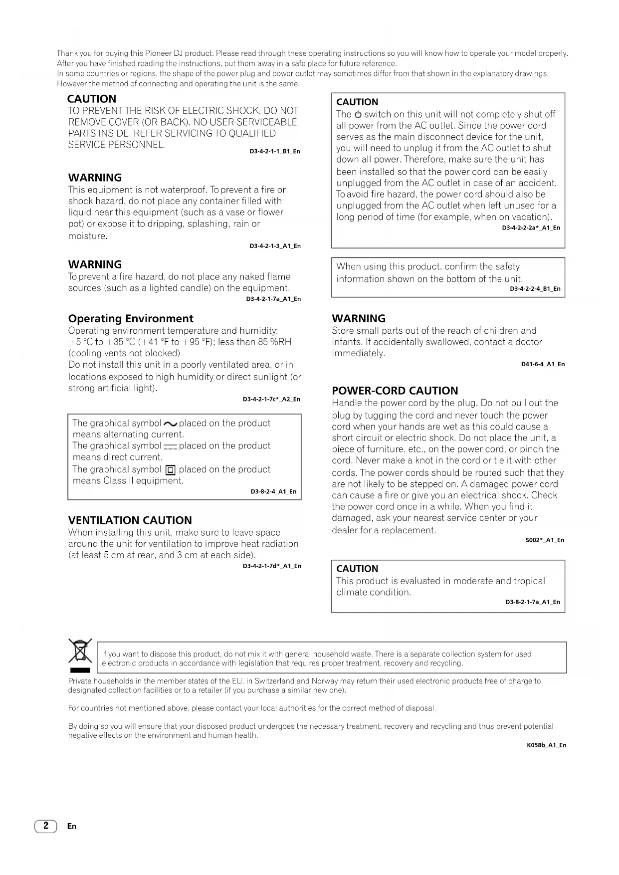
1 Cord hook
Hook the power cord of the AC adaptor to avoid accidentally disconnecting it from the unit.
2 switch (page 10)
This switch is between off and on for this unit.
3 DC IN terminal (page 8)
Connect the DC plug of the supplied AC adaptor. Connect all other equipment, then connect the power cord. Only use the power cord and AC adapter supplied with this unit.
4 MASTER2 output terminals (page 9)
Connect to the analog input terminals of a power amplifier, etc.
5 MASTER1 output terminals (page 9)
Connect your equipment, such as a power speaker or a power amplifier, to the analog input terminal. Use these terminals as balanced output. Do not accidentally insert the power cord of the supplied AC adaptor or the power cord of the equipment. Do not connect to a terminal which can supply phantom power.
6 PHONO input terminals (page 8)
Connect to a phono level (MM cartridge) output device. Do not input line level signals.
7 LINE input terminals (page 8)
Connect to a DJ player or a line level output component.
8 SIGNAL GND terminal (page 8)
Connect an analog player's ground wire. This helps reduce noise when the analog player is connected.
9 MIC input terminal (page 8)
Connect a microphone.
10 USB terminal (page 8)
Connect to a computer.
11 Kensington security slot
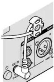
Control Panel
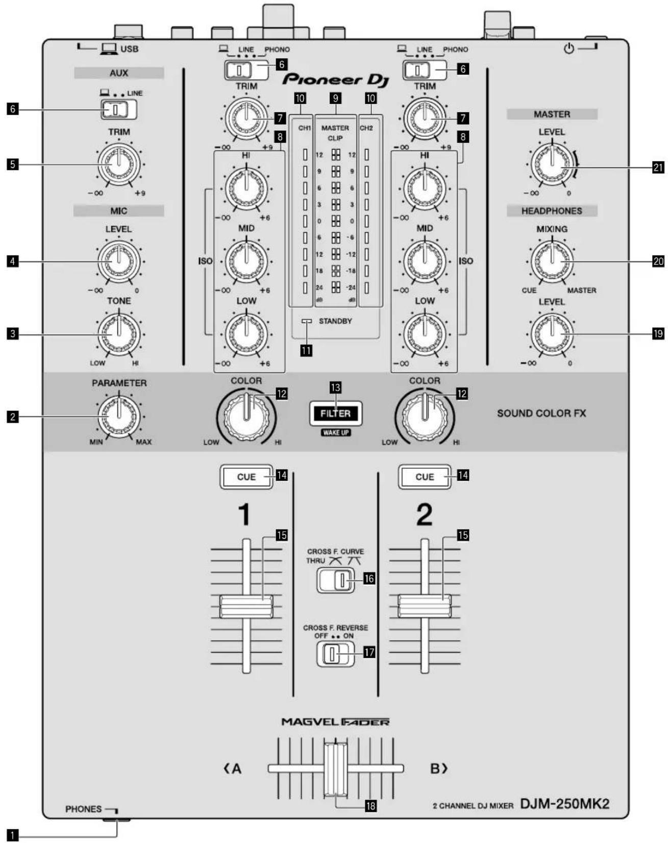
1 PHONES terminal (page 9)
Connect headphones.
This unit supports 1/4" stereo phone plugs and 3.5 mm stereo mini plugs.
2 PARAMETER control
Adjust the SOUND COLOR FX parameter.
3 MIC TONE control (page 10)
Adjust the sound quality from the microphone.
4 MIC LEVEL control (page 10)
Adjust the volume to output from the microphone.
5 AUX TRIM control
Adjust the volume from the AUX input.
6 Input selector switches (page 10)
Select an input source on each channel.
7 TRIM control (page 10)
Adjust the volume from each channel.
8 ISO (HI, MID, LOW) controls (page 10)
Adjust the sound quality of the respective channels.
9 Master Level indicator (page 10)
It shows the volume from the MASTER output.
When the volume is too loud, the [CLIP] indicator flashes. In this case, turn down the volume.
— Slow flashing: sound will become distorted. — Fast flashing: sound is distorted.
10 Channel Level indicator (page 10)
It shows the volume before passing the channel fader.
11 STANDBY indicator
This indicator is lit when the unit is in the standby state.
12 COLOR control
Change the parameters of the SOUND COLOR FX of the different channels.
13 FILTER button
Turn on/off the SOUND COLOR FX effects.
— WAKE UP: Press this button to cancel the standby state.
14 CUE button (page 10)
Press the [CUE] button for the channel you want to monitor.
15 Channel Fader (page 10)
Adjust the volume of each channel
16 CROSS F.CURVE (THRU, 7) selector switch (page10)
This switches the cross fader curve characteristics.
17 CROSS F. REVERSE switch (page 10)
Turn on/off the cross fader reverse function.
18 Cross fader (page 10)
Sound outputs following the curve selected by the [CROSS F.CURVE] selector switch.
19 HEADPHONES LEVEL control (page 10)
Adjust the level of audio signals output from the headphones.
20 HEADPHONES MIXING control (page 10)
Adjust the monitor volume balance of the sound of channels for which the [CUE] button is pressed and the sound of the [MASTER] channel.
21 MASTER LEVEL control (page 10)
Adjust the level of audio signals from the [MASTER1] or [MASTER2] output.
Do not pull on the channel fader and cross fader knobs with excessive force. The knobs have a structure by which they cannot be pulled off easily. Pulling the knobs strongly may result in damaging the unit.
Connections
Be sure to turn off the power and unplug the power cord from the power outlet whenever making or changing connections.
Connect the power cord after all the connections between devices have been completed.
Be sure to use the included power cord.
Refer to the operating instructions for the component to be connected.
- Connect this unit and the computer directly using a USB cable.
- Use USB cables that conform to USB 2.0.
• USB hubs cannot be used.
Connecting input terminals

Pioneer DJ's sampler, etc.
Connecting output terminals
1 Be sure to use the [MASTER1] output terminals only for a balanced output. Connection with an unbalanced input (such as RCA) using an XLR to RCA converter cable (or converter adapter), etc., may lower the sound quality and/or result in noise. For connection with an unbalanced input (such as RCA), use the [MASTER2] output terminals.
2 Be careful not to accidentally insert the power cord of another unit to the [MASTER1] output terminals. Do not connect a terminal which is supplied with phantom power to the [MASTER1] output terminals.
Operation
Basic Operation
Outputting sound
1 Press the ⏻ switch.
Turn on the unit.
2 Set the input selector switches.
Select the input sources for the different channels from among the devices connected to this unit.
— [☐]: Audio from a computer connected to the [USB] terminal is selected.
— [LINE]: Audio from a device connected to the [LINE] input terminal is selected.
— [PHONO]: Audio from analog players connected to the [PHONO] input terminals is selected.
3 Turn the [TRIM] control.
Adjust the level of audio signals input for each channel.
The corresponding channel level indicator lights when audio signals are being properly input to that channel.
4 Move the channel fader up.
Adjust the level of audio signals output for each channel.
5 Set the cross fader.
This operation is not necessary when the |CROSS F.CURVE| selector switch is set to [THRU].
6 Turn the [MASTER LEVEL] control.
Audio signals are output from the [MASTER1] and [MASTER2] output terminals.
The master level indicator lights.
Adjusting the sound quality
Turn the [ISO (HI, MID, LOW)] controls for the respective channels.
The adjustable ranges for the respective controls are as shown below.
— [HI]: -∞ dB to +6 dB (20 kHz)
— [MID]: -∞ dB to +6 dB (1 kHz)
— [LOW]: -∞ dB to +6 dB (20 Hz)
Monitoring sound with headphones
1 Connect headphones to the [PHONES] terminal.
2 Press the [CUE] button(s) for the channel(s) you want to monitor.
3 Turn the [HEADPHONES MIXING] control.
Adjust the monitor volume balance of sound from channels for which the [CUE] button is pressed and the [MASTER] channel.
4 Turn the [HEADPHONES LEVEL] control.
Adjust the level of audio signals for the headphones.
Setting the fader curve
Switch the [CROSS F.CURVE (THRU, 7)] selector switch.
— |THRU|: Set to this option when not using the cross fader.
— |X|The curve is increased slowly.
— The curve is increased steeply. (If the cross fader is moved from the extreme left or right position, output sound is changed to the opposite side immediately.)
Using the fader reverse function
Turn on the [CROSS F.REVERSE] switch.
When turning on the [CROSS F.REVERSE] switch, the operating direction of the cross fader is reversed.
Using AUX
1 Set the input selector switch for AUX.
— [☐]: Audio from a computer connected to the [USB] terminal is selected.
— [LINE]: Audio from a device connected to the [LINE] input terminal is selected.
2 Turn the [AUX TRIM] control.
Adjust the level of audio signal input for the AUX channel.
Using a microphone
1 Connect a microphone to the [MIC] input terminal.
2 Turn the [MIC LEVEL] control.
Adjust the volume from the [MIC] input terminal.
- If the control is turned to the extreme right position, the sound output will be too loud.
3 Turn the [MIC TONE] control to adjust the sound quality.
— When turning the control to the [LOW] position, the high frequency is attenuated.
0 to -12 dB (10 kHz)
— When turning the control to the [HI] position, the low frequency is attenuated.
0 to -12 dB (100 Hz)
Additional information
Troubleshooting
- If you think that there is something wrong with this unit, check the items below, and check [FAQ] for [DJM-250MK2] on the Pioneer DJ site. http://pioneerdj.com/support/ Also, check the connected devices. If the problem cannot be resolved, ask your nearest Pioneer authorized service center or your dealer to carry out repair work.
- This unit may not operate properly due to static electricity or other external influences. In such cases, normal operation may be restored by unplugging the power cord then plugging it back in.
| Problem Check Remedy | ||
| There is no sound or the volume is too low. | Is the input selector switch set to the proper position? | Set the input selector switch to the input source for the channel. (page 10) |
| Are the connection cables properly connected? Connect the connection cables properly. (page 8) | ||
| Are the terminals and plugs dirty? Clean the terminals and plugs before making connections. | ||
| Is [MASTER OUT ATT.] set to [-6 dB], etc? | Set [MASTER OUT ATT.] on the [UTILITY].* | |
| Sound is distorted. | Is the sound level output from the [MASTER] channel appropriately set? | Adjust the [MASTER LEVEL] control so that the master channel level indicator lights at around [0 dB] at the peak level. (page 10) |
| Set [MASTER OUT ATT.] on the [UTILITY] to [-6 dB] or [-12 dB].* | ||
| Is the level of audio input to each channel properly set? | Adjust the [TRIM] control so that the channel level indicator lights at about [0 dB] at the peak level. | |
| Cross fade does not work. Is the [CROSS F. CURVE] selector switch set properly? | If [THRU] is selected, cross fader does not work. Set the [CROSS F. CURVE] selector switch properly. (page 10) | |
| Sound is distorted when an analog player is connected to this unit's [PHONO] terminals.Or, lighting of the channel level indicator does not change even when the [TRIM] control is turned. | Have you connected an analog player with a built-in phono equalizer? | Connect the analog player with built-in phono equalizer to the [LINE] input terminals.(page8) |
| If the analog player with built-in phono equalizer has a PHONO/LINE selector switch, set it to PHONO. | ||
| Is an audio interface for computers connected between the analog player and this unit? | If the output of the audio interface for computers is line level, connect it to the [LINE] input terminals. (page 8) | |
| If the analog player has a PHONO/LINE selector switch, set it to PHONO. | ||
* For details on how to change the settings on the [UTILITY], see "Changing the settings" in the Operating Instructions.
Changing the settings
- For details on how to change the settings of this unit, see "Changing the settings" in the Operating Instructions.
About trademarks and registered trademarks
- Pioneer DJ is a trademark of PIONEER CORPORATION, and is used under license. rekordbox is a trademark or registered trademark of the Pioneer DJ Corporation.
The names of companies and products mentioned herein are trademarks or registered trademarks of their respective owners.
Cautions on copyrights
rekordbox restricts playback and duplication of copyright-protected music contents.
- When coded data, etc., for protecting the copyright is embedded in the music contents, it may not be possible to operate the program normally.
- When rekordbox detects that coded data, etc., for protecting the copyright is embedded in the music contents, processing (playback, reading, etc.) may stop.
Recordings you have made are for your personal enjoyment and according to copyright laws may not be used without the consent of the copyright holder.
- Music recorded from CDs, etc., is protected by the copyright laws of individual countries and by international treaties. It is the full responsibility of the person who has recorded the music to ensure that it is used legally.
- When handling music downloaded from the Internet, etc., it is the full responsibility of the person who has downloaded the music to ensure that it is used in accordance with the contract concluded with the download site.
Specifications
AC adapter
Power.....AC 100 V to 240 V, 50 Hz/60 Hz
Rated current 0.6 A
Rated output..... DC 12 V, 2 A
Power consumption (standby) 0.5 W
General - Main Unit
Power consumption.....DC 12 V, 600 mA
Main unit weight 3.0 kg
Max. dimensions
..... 230 mm (width) × 107.9 mm (height) × 319.5 mm (depth)
Tolerable operating temperature ....+5 °C to +35 °C
Tolerable operating humidity 5% to 85% (no condensation)
Audio Section
Sampling rate 48 kHz
MASTER D/A converter 24 bits
Other A/D and D/A converters 24 bits
Frequency characteristic LINE 20 Hz to 20 kHz
S/N ratio (rated output) PHONO....80 dB
LINE 94 dB
MIC 77 dB
AUX 90 dB
Total harmonic distortion (LINE — MASTER1)....0.005 %
Standard input level / Input impedance
PHONO....-52 dBu/47 kΩ
LINE -12 dBu/47 kΩ
MIC -52 dBu/8.5 kΩ
AUX -12 dBu/47 kΩ
Standard output level / Load impedance / Output impedance
MASTER1 +6 dBu/10 kΩ/1 kΩ or lower
MASTER2....+2 dBu/10 kΩ/390 Ω or lower
PHONES ....+8.0 dBu/32 Ω/2 Ω or lower
Rated output level / Load impedance
MASTER1 +25 dBu/10 kΩ
MASTER2....+21 dBu/10 kΩ
Crosstalk (LINE) 90 dB
Channel equalizer characteristic
HI - dB to +6 dB (20 kHz)
MID....-∞ dB to +6 dB (1 kHz)
LOW - dB to +6 dB (20 Hz)
Microphone equalizer characteristic
LOW 0 dB to -12 dB (10 kHz)
HI 0 dB to -12 dB (100 Hz)
Input / Output terminals
PHONO input terminal
RCA pin jack....2 sets
LINE input terminal
RCA pin jack....2 sets
MIC input terminal
1/4" TS jack....1 set
AUX input terminal
RCA pin jack....1 set
MASTER output terminal
XLR connector....1 set
RCA pin jack....1 set
PHONES output terminal
1/4" stereo phone jack....1 set
3.5 mm stereo mini jack....1 set
USB terminal
B type....1 set
- The specifications and design of this product are subject to change without notice.
• © 2017 Pioneer DJ Corporation. All rights reserved.
WAARSCHUWING NETSNOER
2 ⏻-schakelaar (pagina 10)
Pioneer DJ's sampler, enz.
Em especial, leia as "INSTRUÇÕES DE SEGURANÇA IMPORTANTES".
2 Interruptor Ⓧ (página 10)
© 2017 Pioneer DJ Corporation. All rights reserved.
Pioneer DJ Corporation
6F, Yokohama i-Mark Place, 4-4-5 Minatomirai, Nishi-ku, Yokohama, Kanagawa 220-0012 JAPAN
Pioneer DJ 株式会社
Pioneer DJ Europe Limited
Anteros Building, Odyssey Business Park, West End Road, South Ruislip, Middlesex, HA4
6QQ, U.K. TEL: +44-203-7617-220
Pioneer DJ Americas, Inc.
2050 W. 190th Street, Suite 109, Torrance, CA 90504, U.S.A. TEL: +1 (424) 488-0480
PIONEER ELECTRONICS ASIACENTRE PTE. LTD.
2 Jalan Kilang Barat, #07-01, Singapore 159346 TEL: +65-6378-7888
PIONEER ELECTRONICS AUSTRALIA PTY. LTD.
5 Arco Lane, Heatherton, Victoria, 3202, Australia, TEL: +61-3-9586-6300
PIONEER ELECTRONICS (THAILAND) CO., LTD.
17th Fl., KPN Tower, 719 Rama 9 Road, Bangkapi, Huaykwang, Bangkok 10310
TEL: +66-2-717-0777
PIONEER TECHNOLOGY (MALAYSIA) SDN. BHD
16th Floor, Menara Uni. Asia 1008 Jalan Sultan Ismail 50250 Kuala Lumpur
TEL: +60-3-2697-2920
先鋒股份有限公司
PIONEER INDIA ELECTRONICS PRIVATE LTD.
216, Second Floor, Time Tower, M.G. Road, Sector 28, Gurgaon 122001,
Haryana, India TEL: +91-124-463-6100
Сделано в Малайзии
PDJ 001 all


- CAUTION
- WARNING
- Operating Environment
- VENTILATION CAUTION
- POWER-CORD CAUTION
- Contents
- How to read this manual
- Before start
- Part names and functions
- Connections
- Operation
- Additional information
- Before start
- Features
- What's in the box
- Note
- Viewing the Operating Instructions
- Part names and functions
- Cord hook
- switch (page 10)
- DC IN terminal (page 8)
- MASTER2 output terminals (page 9)
- MASTER1 output terminals (page 9)
- PHONO input terminals (page 8)
- LINE input terminals (page 8)
- SIGNAL GND terminal (page 8)
- MIC input terminal (page 8)
- USB terminal (page 8)
- Kensington security slot
- Connections
- Connecting output terminals
- Operation
- Basic Operation
- Outputting sound
- Press the ⏻ switch.
- Set the input selector switches.
- Turn the [TRIM] control.
- Move the channel fader up.
- Set the cross fader.
- Turn the [MASTER LEVEL] control.
- Adjusting the sound quality
- Turn the [ISO (HI, MID, LOW)] controls for the respective channels.
- Monitoring sound with headphones
- Setting the fader curve
- Using the fader reverse function
- Turn on the [CROSS F.REVERSE] switch.
- Using AUX
- Set the input selector switch for AUX.
- Turn the [AUX TRIM] control.
- Using a microphone
- Connect a microphone to the [MIC] input terminal.
- Turn the [MIC LEVEL] control.
- Turn the [MIC TONE] control to adjust the sound quality.
- Additional information
- Troubleshooting
- Changing the settings
- About trademarks and registered trademarks
- Cautions on copyrights
- Specifications
- AC adapter
- General - Main Unit
- Audio Section
- Input / Output terminals
- WAARSCHUWING NETSNOER
- ⏻-schakelaar (pagina 10)
- Interruptor Ⓧ (página 10)
- Pioneer DJ Corporation
- Pioneer DJ 株式会社
- Pioneer DJ Europe Limited
- Pioneer DJ Americas, Inc.
- PIONEER ELECTRONICS ASIACENTRE PTE. LTD.
- PIONEER ELECTRONICS AUSTRALIA PTY. LTD.
- PIONEER ELECTRONICS (THAILAND) CO., LTD.
- PIONEER TECHNOLOGY (MALAYSIA) SDN. BHD
- 先鋒股份有限公司
- PIONEER INDIA ELECTRONICS PRIVATE LTD.
Brand : PIONEER
Model : DJM250MK2
Category : DJ Equipment