PCC780 - Saw Porter-Cable - Free user manual and instructions
Find the device manual for free PCC780 Porter-Cable in PDF.
User questions about PCC780 Porter-Cable
0 question about this device. Answer the ones you know or ask your own.
Ask a new question about this device
Download the instructions for your Saw in PDF format for free! Find your manual PCC780 - Porter-Cable and take your electronic device back in hand. On this page are published all the documents necessary for the use of your device. PCC780 by Porter-Cable.
USER MANUAL PCC780 Porter-Cable
Thank you for choosing PORTER-CABLE! To register your new product, go to:
www.portercable.com/ServiceAndSupport/ProductRegistration.aspx
Merci d'avoir choisi PORTER-CABLE! Consulter le site Web www.portercable.com/ServiceAndSupport/
Definitions: Safety Alert Symbols and Words
This instruction manual uses the following safety alert symbols and words to alert you to hazardous situations and your risk of personal injury or property damage.

text_image
DANGER: Indicates an imminently hazardous situation which, if not avoided, will result in death or serious injury. WARNING: Indicates a potentially hazardous situation which, if not avoided, could result in death or serious injury. CAUTION: Indicates a potentially hazardous situation which, if not avoided, may result in minor or moderate injury. (Used without word) Indicates a safety related message.NOTICE: Indicates a practice not related to personal injury which, if not avoided, may result in property damage.
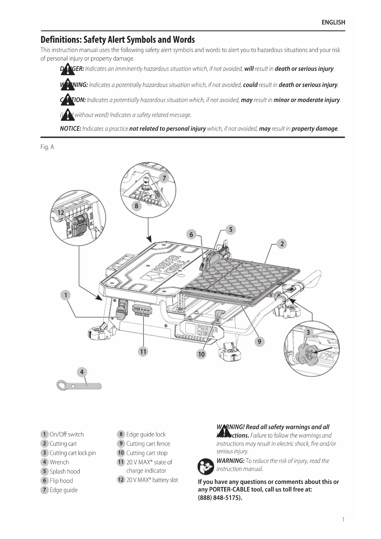
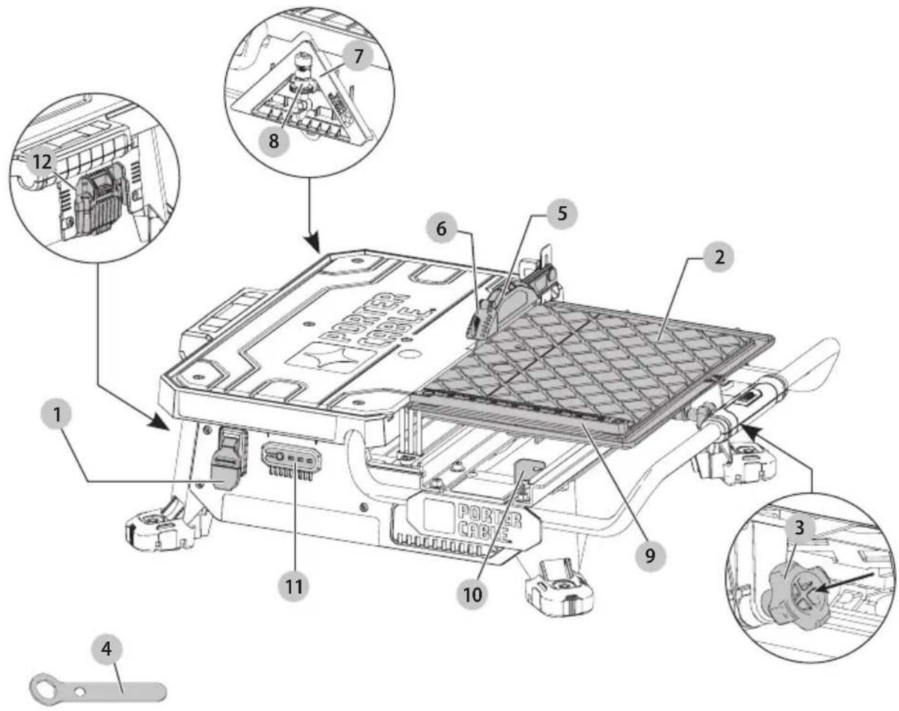
Fig. A
text_image
Technical diagram of a computer hardware module with numbered components and exploded view, highlighting ports and connectors.1 On/Off switch
2 Cutting cart
3 Cutting cart lock pin
4 Wrench
5 Splash hood
6 Flip hood
7 Edge guide
8 Edge guide lock
9 Cutting cart fence
10 Cutting cart stop
11 20 V MAX* state of charge indicator
12 20 V MAX* battery slot
WARNING! Read all safety warnings and all instructions. Failure to follow the warnings and instructions may result in electric shock, fire and/or serious injury.
WARNING: To reduce the risk of injury, read the instruction manual.
If you have any questions or comments about this or any PORTER-CABLE tool, call us toll free at: (888) 848-5175).
English
GENERAL POWER TOOL SAFETY WARNINGS
WARNING! Read all safety warnings and all instructions. Failure to follow the warnings and instructions may result in electric shock, fire and/or serious injury.
SAVE ALL WARNINGS AND INSTRUCTIONS FOR FUTURE REFERENCE
The term "power tool" in the warnings refers to your mains-operated (corded) power tool or battery-operated (cordless) power tool.
WARNING: Never use saw with salt water or a radioactive fluid.
WARNING: when using electric tools, basic safety precautions should always be followed to reduce risk of fire, electric shock, and personal injury, including the following:
- KEEP GUARDS IN PLACE and in working order.
- REMOVE ADJUSTING KEYS AND WRENCHES. Form habit of checking to see that keys and adjusting wrenches are removed from tool before turning it on.
- KEEP WORK AREA CLEAN. Cluttered areas and benches invite injuries.
- DON'T USE IN DANGEROUS ENVIRONMENT. Don't use power tools in damp or wet locations, or expose them to rain or snow. Keep work area well lighted.
- KEEP CHILDREN AWAY. All visitors should be kept safe distance from work area.
- MAKE WORKSHOP KID PROOF with padlocks, master switches, or by removing starter keys.
- DON'T FORCE TOOL. It will do the job better and safer at the rate for which it was designed.
- USE RIGHT TOOL. Don't force tool or attachment to do a job for which it was not designed
- WEAR PROPER APPAREL. Do not wear loose clothing, gloves, neckties, rings, bracelets, or other jewelry which may get caught in moving parts. Nonslip footwear is recommended. Wear protective hair covering to contain long hair. Air vents often cover moving parts and should also be avoided.
- ALWAYS USE SAFETY GLASSES. Also use face or dust mask if cutting operation is dusty. Everyday eyeglasses only have impact resistant lenses, they are not safety glasses.
- SECURE WORK. Always place tile flat on cart and securely against fence.
- NEVER USE A PAN HEATER OR OTHER HEAT SOURCE FOR HEATING WATER. Damage to the tool, fire or personal injury could result.
- DON'T OVERREACH. Keep proper footing and balance at all times.
-
MAINTAIN TOOLS WITH CARE. Keep tools sharp and clean for best and safest performance. Follow instructions for lubricating and changing accessories.
-
USE RECOMMENDED ACCESSORIES. Consult the instruction manual for recommended accessories. The use of improper accessories may cause risk of injury to persons.
- NEVER STAND ON TOOL. Serious injury could occur if the tool is tipped or if the cutting tool is unintentionally contacted.
- CHECK DAMAGED PARTS. Before further use of the tool, a guard or other part that is damaged should be carefully checked to determine that it will operate properly and perform its intended function—check for alignment of moving parts, binding of moving parts, breakage of parts, mounting, and any other conditions that may affect its operation. A guard or other part that is damaged should be properly repaired or replaced.
- DIRECTION OF FEED. Feed work into a cutting wheel with the direction of rotation only.
- NEVER LEAVE TOOL RUNNING UNATTENDED. TURN POWER OFF. Don't leave tool until it comes to a complete stop.
- REPLACEMENT PARTS. When servicing, use only identical replacement parts.
- ENSURE THE SWITCH IS IN THE OFF POSITION BEFORE INSERTING BATTERY PACK. Inserting battery pack inot power tools that have the switch on invites accidents.
- RECHARGE ONLY WITH THE CHARGER SPECIFIED BY THE MANUFACTURER. A charger that is suitable for one type of battery pack may create a risk of fire when used with another battery pack.
- USE POWER TOOLS ONLY WITH SPECIFICALLY DESIGNATED BATTERY PACKS. Use of any other battery packs may create a risk of injury and fire.
- WHEN BATTERY PACK IS NOT IN USE, KEEP IT AWAY FROM OTHER METAL OBJECTS LIKE PAPER CLIPS, COINS, KEYS, NAILS, SCREWS OR OTHER SMALL METAL OBJECTS THAT CAN MAKE A CONNECTION FROM ONE TERMINAL TO ANOTHER. Shorting the battery terminals together may cause burns or a fire.
- UNDER ABUSIVE CONDITIONS, LIQUID MAY BE EJECTED FROM THE BATTERY; AVOID CONTACT. IF CONTACT ACCIDENTALLY OCCURS, FLUSH WITH WATER. IF LIQUID CONTACTS EYES, ADDITIONALLY SEEK MEDICAL HELP. Liquid ejected from the battery may cause irritation or burns.
- DISCONNECT THE BATTERY PACK FROM THE TOOL OR PLACE THE SWITCH IN THE LOCKED OR OFF POSITION BEFORE MAKING ANY ADJUSTMENTS, CHANGING ACCESSORIES, OR STORING THE TOOL. Such preventive safety measures reduce the risk of starting the tool accidentally.
• HAVE YOUR POWER TOOL SERVICED BY A QUALIFIED REPAIR PERSON USING ONLY IDENTICAL REPLACEMENT PARTS. This will ensure that the safety of the power tool is maintained.
Additional Safety Rules for Wet Tile Saw
CAUTION: Wear appropriate hearing protection during use. Under some conditions and duration of use, noise from this product may contribute to hearing loss.
CANITION: Do not connect unit to electrical power source until complete instructions are read and understood.
- Use safety equipment. Always wear eye protection. Dust mask, non-skid safety shoes, hard hat, or hearing protection must be used for appropriate conditions.
- Keep hands out of path of saw blade. NEVER CUT A PIECE WHERE HAND WOULD BE 3" (76 mm) OR LESS FROM BLADE.
- Do not perform any operation freehand, that is without holding the workpiece firmly against the fence or edge guide.
- Never reach in back of the blade.
- DON'T - Cut dry. If blade is not cooled with water, serious damage will occur. Dry cutting will increase exposure to harmful airborne dust.
- Turn off the tool and wait for blade to stop before moving the workpiece or changing settings.
- To reduce risk of injury, return the cart to the full rear position after each cut.
- DO - Make certain the blade rotates in the correct direction as indicated by the arrow on the blade.
• DO - Always use the splash hood.
- DO - Be sure all clamp handles and knobs are tight before starting any operation.
- DO - Be sure all blade and clamp washers are clean and recessed sides of collars are against blade. Tighten arbor nut securely.
• DO - Keep the blade properly aligned.
- DO - Keep the motor air slots free of chips and dirt.
- DO – Always empty water from the reservoir and remove the battery pack before transporting. Water can splash into electrical components.
- DO - Keep hands out of the path of the saw blade.
- DON'T - Attempt to operate on anything but designated voltage. Incorrect voltage may result in shock, fire, or unpredictable operation.
- DON'T - Use blades larger or smaller than those which are recommended.
- DON'T - Force cutting action. Allow motor to reach full speed before cutting. Stalling or partial stalling of motor can cause major damage.
- DON'T - Use metal cutting abrasive wheels. The excessive heat and abrasive particles generated by them will damage the saw.
- DO - Use continuous rim wheels only, no serrated edges or toothed blades.
• DON'T - Allow anyone to stand behind saw.
- DON'T - Place either hand in the blade area when the saw is connected to the power source.
- DON'T - Use blades rated less than 5000 R.P.M.
- DON'T - Place hands closer than 3" (76 mm) from the saw blade.
- DON'T - Reach behind or underneath the saw unless it is turned off and unplugged.
- DON'T - Move either hand from saw or workpiece until the blade has stopped.
Additional Safety Information
WARNING: ALWAYS use safety glasses. Everyday eyeglasses are NOT safety glasses. Also use face or dust mask if cutting operation is dusty. ALWAYS WEAR CERTIFIED SAFETY EQUIPMENT:
• ANSI Z87.1 eye protection (CAN/CSA Z94.3),
• ANSI S12.6 (S3.19) hearing protection,
• NIOSH/OSHA/MSHA respiratory protection.
WARNING: Some dust created by power sanding, sanding, grinding, drilling, and other construction activities contains chemicals known to the State of California to cause cancer, birth defects or other reproductive harm. Some examples of these chemicals are:
- lead from lead-based paints,
• crystalline silica from bricks and cement and other masonry products, and
• arsenic and chromium from chemically-treated lumber.
Your risk from these exposures varies, depending on how often you do this type of work. To reduce your exposure to these chemicals: work in a well ventilated area, and work with approved safety equipment, such as those dust masks that are specially designed to filter out microscopic particles.
- Avoid prolonged contact with dust from power sanding, sawing, grinding, drilling, and other construction activities. Wear protective clothing and wash exposed areas with soap and water. Allowing dust to get into your mouth, eyes, or lay on the skin may promote absorption of harmful chemicals.
WARNING: Use of this tool can generate and/or disperse dust, which may cause serious and permanent respiratory or other injury. Always use NIOSH/OSHA approved respiratory protection appropriate for the dust exposure. Direct particles away from face and body.
WARNING: Always wear proper personal hearing protection that conforms to ANSI S12.6 (S3.19)
during use. Under some conditions and duration of use, noise from this product may contribute to hearing loss.
• Air vents often cover moving parts and should be avoided. Loose clothes, jewelry or long hair can be caught in moving parts.
The label on your tool may include the following symbols. The symbols and their definitions are as follows:
V....volts 😊...... Class I Construction
Hz ....hertz (grounded)
min....minutes .../min....per minute
or DC.....direct current BPM.....beats per minute
English
| IPM......impacts per minute | n0......no load speed |
| RPM......revolutionsper minute | n......rated speed |
| ±......carthing terminal | |
| sfpm......surface feet per minute | ▲......safely alert symbol |
| ▲......visible radiation | |
| SPM......strokes per minute | ●......wearrespiratory |
| A......amperes | protection |
| W......watts | ●......weareye |
| ~or AC......alternating current | protection |
| ~or AC/DC....alternatingor direct current | ○......wearhearing protection |
| ClassII Construction (double insulated) | ●......readall documentation |
BATTERIES AND CHARGERS
The battery pack is not fully charged out of the carton. Before using the battery pack and charger, read the safety instructions below and then follow charging procedures outlined. When ordering replacement battery packs, be sure to include the catalog number and voltage. Your tool uses a PORTER-CABLE charger. Be sure to read all safety instructions before using your charger. Consult the chart at the end of this manual for compatibility of chargers and battery packs.
READ ALL INSTRUCTIONS
Important Safety Instructions for All Battery Packs
WARNING: Read all safety warnings and all instructions for the battery pack, charger and power tool. Failure to follow the warnings and instructions may result in electric shock, fire and/or serious injury.
- Do not charge or use the battery pack in explosive atmospheres, such as in the presence of flammable liquids, gases or dust. Inserting or removing the battery pack from the charger may ignite the dust or fumes.
- NEVER force the battery pack into the charger. DO NOT modify the battery pack in any way to fit into a non-compatible charger as battery pack may rupture causing serious personal injury. Consult the chart at the end of this manual for compatibility of batteries and chargers.
- Charge the battery packs only in designated PORTER-CABLE chargers.
• DO NOT splash or immerse in water or other liquids.
- Do not store or use the tool and battery pack in locations where the temperature may reach or exceed 104 °F (40 °C) (such as outside sheds or metal buildings in summer). For best life store battery packs in a cool, dry location.
NOTE: Do not store the battery packs in a tool with the trigger switch locked on. Never tape the trigger switch in the ON position.
- Do not incinerate the battery pack even if it is severely damaged or is completely worn out. The battery pack can explode in a fire. Toxic fumes and materials are created when lithium ion battery packs are burned.
- If battery contents come into contact with the skin, immediately wash area with mild soap and water. If battery liquid gets into the eye, rinse water over the open eye for 15 minutes or until irritation ceases. If medical attention is needed, the battery electrolyte is composed of a mixture of liquid organic carbonates and lithium salts.
- Contents of opened battery cells may cause respiratory irritation. Provide fresh air. If symptoms persist, seek medical attention.
WARNING: Burn hazard. Battery liquid may be flammable if exposed to spark or flame.
WARNING: Fire hazard. Never attempt to open the battery pack for any reason. If the battery pack case is cracked or damaged, do not insert into the charger. Do not crush, drop or damage the battery pack. Do not use a battery pack or charger that has received a sharp blow, been dropped, run over or damaged in any way (e.g., pierced with a nail, hit with a hammer, stepped on). Damaged battery packs should be returned to the service center for recycling.
Transportation
WARNING: Fire hazard. Do not store or carry the battery pack so that metal objects can contact exposed battery terminals. For example, do not place the battery pack in aprons, pockets, tool boxes, product kit boxes, drawers, etc., with loose nails, screws, keys, etc. Transporting batteries can possibly cause fires if the battery terminals inadvertently come in contact with conductive materials such as keys, coins, hand tools and the like. The US Department of Transportation Hazardous Material Regulations (HMR) actually prohibit transporting batteries in commerce or on airplanes in carry-on baggage UNLESS they are properly protected from short circuits. So when transporting individual battery packs, make sure that the battery terminals are protected and well insulated from materials that could contact them and cause a short circuit.
The RBRC® Seal
The RBRC® (Rechargeable Battery Recycling Corporation) Seal on the nickel cadmium, nickel metal hydride or lithium-ion batteries (or battery packs) indicates that the costs to recycle these batteries

(or battery packs) at the end of their useful life have already been paid by PORTER-CABLE. In some areas, it is illegal to place spent nickel cadmium, nickel metal hydride or lithium-ion batteries in the trash or municipal solid waste stream and the Call 2 Recycle® program provides an environmentally conscious alternative.
Call 2 Recycle, Inc., in cooperation with PORTER-CABLE and other battery users, has established the program in
the United States and Canada to facilitate the collection of spent nickel cadmium, nickel metal hydride or lithium-ion batteries. Help protect our environment and conserve natural resources by returning the spent nickel cadmium, nickel metal hydride or lithium-ion batteries to an authorized PORTER-CABLE service center or to your local retailer for recycling. You may also contact your local recycling center for information on where to drop off the spent battery. RBRC® is a registered trademark of Call 2 Recycle, Inc.
Wireless Certifications and Safety Information
• This device is CAN ICES-3(B)/NMB-3(B) compliant.
- This device complies with Part 15 of the FCC rules and Industry Canada License-exempt RSS standard(s).
Operation is subject to the following two conditions:
– This device may not cause harmful interference, and
- This device must accept any interference received, including interference that may cause undesired operation.
This equipment has been tested and found to comply with the limits for a Class B digital device, pursuant to Part 15 of the FCC Rules. These limits are designed to provide reasonable protection against harmful interference in a residential installation. This equipment generates, uses and can radiate radio frequency energy and, if not installed and used in accordance with the instructions, may cause harmful interference to radio communications. However, there is no guarantee that interference will not occur in a particular installation. If this equipment does cause harmful interference to radio or television reception, which can be determined by turning the equipment off and on, the user is encouraged to try to correct the interference by one or more of the following measures:
- Reorient or relocate the receiving antenna.
- Increase the separation between the equipment and adaptor.
- Connect the equipment into an outlet on a circuit different from that to which the adaptor is connected.
-
Consult the dealer or an experienced radio/TV technician for help.
-
Changes or modifications to this equipment not expressly approved by the manufacturer could void the user's authority to operate the device. This Class B digital apparatus complies with Canadian ICES-003.
- Under Industry Canada regulations, this radio transmitter may only operate using an antenna of a type and maximum (or lesser) gain approved for the transmitter by Industry Canada. To reduce potential radio interference to other users, the antenna type and its gain should be so chosen that the equivalent isotropically radiated power (e.i.r.p.) is not more than that necessary for successful communication.
- To comply with FCC and Industry Canada RF radiation exposure limits for general population, the antenna used for this device must not be co-located or operating in conjunction with any other antenna or transmitter.
Important Safety Instructions for All Battery Chargers
WARNING: Read all safety warnings and all instructions for the battery pack, charger and power tool. Failure to follow the warnings and instructions may result in electric shock, fire and/or serious injury.
- DO NOT attempt to charge the battery pack with any chargers other than the ones in this manual. The charger and battery pack are specifically designed to work together.
• These chargers are not intended for any uses other than charging PORTER-CABLE rechargeable batteries. Any other uses may result in risk of fire, electric shock or electrocution. - Do not expose the charger to rain or snow.
- Pull by the plug rather than the cord when disconnecting the charger. This will reduce the risk of damage to the electric plug and cord.
- Make sure that the cord is located so that it will not be stepped on, tripped over or otherwise subjected to damage or stress.
- Do not use an extension cord unless it is absolutely necessary. Use of improper extension cord could result in risk of fire, electric shock or electrocution.
- When operating a charger outdoors, always provide a dry location and use an extension cord suitable for outdoor use. Use of a cord suitable for outdoor use reduces the risk of electric shock.
- An extension cord must have adequate wire size (AWG or American Wire Gauge) for safety. The smaller the gauge number of the wire, the greater the capacity of the cable, that is, 16 gauge has more capacity than 18 gauge. An undersized cord will cause a drop in line voltage resulting in loss of power and overheating. When using more than one extension to make up the total length, be sure each individual extension contains at least the minimum wire size. The following table shows the correct size to use depending on cord length and nameplate ampere rating. If in doubt, use the next heavier gauge. The lower the gauge number, the heavier the cord.
Minimum Gauge for Cord Sets
| Volts | Total Length of Cord in Feet (meters) | ||||
| 120 V 25 (7.6) | 50 (15.2) 100 (30.5) 150 (45.7) | ||||
| 240 V 50 (15.2) | 100 (30.5) 200 (61.0) 300 (91.4) | ||||
| Ampere Rating | American Wire Gauge | ||||
| More Than | Not More Than | ||||
| 0 6 18 | 16 16 14 | ||||
| 6 10 18 | 16 14 12 | ||||
| 10 12 | 16 16 14 12 | ||||
| 12 16 14 12 Not Recommended | |||||
- Do not place any object on top of the charger or place the charger on a soft surface that might block the ventilation slots and result in excessive internal
English
heat. Place the charger in a position away from any heat source. The charger is ventilated through slots in the top and the bottom of the housing.
- Do not operate the charger with a damaged cord or plug.
- Do not operate the charger if it has received a sharp blow, been dropped or otherwise damaged in any way. Take it to an authorized service center.
- Do not disassemble the charger; take it to an authorized service center when service or repair is required. Incorrect reassembly may result in a risk of electric shock, electrocution or fire.
- Disconnect the charger from the outlet before attempting any cleaning. This will reduce the risk of electric shock. Removing the battery pack will not reduce this risk.
- NEVER attempt to connect 2 chargers together.
- The charger is designed to operate on standard 120V household electrical power. Do not attempt to use it on any other voltage. This does not apply to the vehicular charger.
WARNING: Shock hazard. Do not allow any liquid to get inside the charger. Electric shock may result.
WARNING: Burn hazard. Do not submerge the battery pack in any liquid or allow any liquid to enter the battery pack. Never attempt to open the battery pack for any reason. If the plastic housing of the battery pack breaks or cracks, return to a service center for recycling.
CAUTION: Burn hazard. To reduce the risk of injury, charge only PORTER-CABLE rechargeable battery packs. Other types of batteries may overheat and burst resulting in personal injury and property damage.
NOTICE: Under certain conditions, with the charger plugged into the power supply, the charger can be shorted by foreign material. Foreign materials of a conductive nature, such as, but not limited to, grinding dust, metal chips, steel wool, aluminum foil or any buildup of metallic particles should be kept away from the charger cavities. Always unplug the charger from the power supply when there is no battery pack in the cavity. Unplug the charger before attempting to clean.
Charging a Battery
PORTER-CABLE chargers are designed to charge PORTER-CABLE battery packs. Charge times are: PCC690L in 40–80 mins., PCC691L in 70–140 mins., PCC692/PCC692L in 40–80 mins., and PCC695L/PCC699L in 65-240 mins. depending on the pack being charged.
- Plug the charger into an appropriate outlet before inserting the battery pack.
- Insert the battery pack into the charger.

- The LED will flash indicating that the battery is being charged.

- The completion of charge is indicated by the LED remaining on continuously. The pack is fully
charged and may be used at this time or left on the charger.
- Recharge discharged batteries as soon as possible after use or battery life may be greatly diminished. For longest battery life, do not discharge batteries fully. It is recommended that the batteries be recharged after each use.
Charger Diagnostics
This charger is designed to detect certain problems that can arise with the battery packs or the power source. Problems are indicated by one LED flashing in different patterns.
Bad Battery

The charger can detect a weak or damaged battery. The LED flashes in the pattern indicated on the label. If you see this bad battery blink pattern, do not continue to charge the battery. Return it to a service center or a collection site for recycling.
Hot/Cold Pack Delay

When the charger detects a battery that is excessively hot or excessively cold, it automatically starts a Hot/Cold Pack Delay, suspending charging until the battery has normalized. After this happens, the charger automatically switches to the Pack Charging mode. This feature ensures maximum battery life. The light flashes in the pattern indicated on the label.
Leaving the Battery in the Charger
The charger and battery pack can be left connected with the LED glowing indefinitely. The charger will keep the battery pack fresh and fully charged. This charger features an automatic tune-up mode which equals or balances the individual cells in the battery pack to allow it to function at peak capacity. Battery packs should be tuned up weekly or whenever the battery no longer delivers the same amount of work. To use the automatic tune-up mode, place the battery pack in the charger and leave it for at least 8 hours.
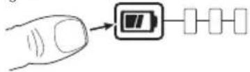
State of Charge Indicator (Fig. B)
Some PORTER-CABLE tools include a state of charge indicator which consists of three green LED lights that indicate the level of charge remaining in the battery pack. The state of charge indicator is an indication of approximate levels of charge remaining in the battery pack according to the following indicators:
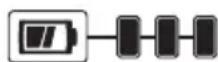
75–100% charged

51–74% charged

< 50% charged

Pack needs to be charged
To actuate the state of charge indicator, press and hold the state of charge indicator button. A combination of the three green LED lights will illuminate designating the level
of charge left. When the level of charge in the battery is below the usable limit, the state of charge indicator will not illuminate and the battery will need to be recharged.
Fig. B
NOTE: The state of charge indicator is only an indication of the charge left on the battery pack. It does not indicate tool functionality and is subject to variation based on product components, temperature and end-user application.
Charger Cleaning Instructions
WARNING: Shock hazard. Disconnect the charger from the AC outlet before cleaning. Dirt and grease
may be removed from the exterior of the charger using a cloth or soft non-metallic brush. Do not use water or any cleaning solutions.
Important Charging Notes
- Longest life and best performance can be obtained if the battery pack is charged when the air temperature is between 65 °F and 75 °F (18 ° – 24 °C). DO NOT charge the battery pack in an air temperature below +40 °F (+4.5 °C), or above +104 °F (+40 °C). This is important and will prevent serious damage to the battery pack.
- The charger and battery pack may become warm to the touch while charging. This is a normal condition, and does not indicate a problem. To facilitate the cooling of the battery pack after use, avoid placing the charger or battery pack in a warm environment such as in a metal shed or an uninsulated trailer.
- If the battery pack does not charge properly:
a. Check operation of receptacle by plugging in a lamp or other appliance;
b. Check to see if receptacle is connected to a light switch which turns power off when you turn out the lights;
c. Move the charger and battery pack to a location where the surrounding air temperature is approximately 65^ F – 75^ F ( 18^ – 24^ C);
d. If charging problems persist, take the tool, battery pack and charger to your local service center.
- The battery pack should be recharged when it fails to produce sufficient power on jobs which were easily done previously. DO NOT CONTINUE to use under these conditions. Follow the charging procedure. You may also charge a partially used pack whenever you desire with no adverse effect on the battery pack.
- Foreign materials of a conductive nature such as, but not limited to, grinding dust, metal chips, steel wool, aluminum foil, or any buildup of metallic particles should be kept away from charger cavities. Always unplug the charger from the power supply when there is no battery pack in the cavity. Unplug the charger before attempting to clean.
- Do not freeze or immerse the charger in water or any other liquid.
Storage Recommendations
- The best storage place is one that is cool and dry, away from direct sunlight and excess heat or cold.
- For long storage, it is recommended to store a fully charged battery pack in a cool dry place out of the charger for optimal results.
NOTE: Battery packs should not be stored completely depleted of charge. The battery pack will need to be recharged before use.
SAVE THESE INSTRUCTIONS FOR FUTURE USE
COMPONENTS (FIG. A)
WARNING: Never modify the power tool or any part of it. Damage or personal injury could result.
Refer to Figure A at the beginning of this manual for a complete list of components.
INTENDED USE
This wet tile saw is designed for cutting a variety of tile and other tile type applications.
DO nOT cut wood, metals or plastics.
DO nOT use under wet conditions or in presence of flammable liquids or gases.
DO nOT let children come into contact with the tool.
Supervision is required when inexperienced operators use this tool.
ASSEMBLY AND ADJUSTMENTS
WARNING: To reduce the risk of serious personal injury, turn tool off and remove the battery pack before transporting, making any adjustments or removing/installing attachments or accessories.
An accidental start-up can cause injury. Make sure the switch is in the OFF position.
Assembly (Fig. A, C–I)
- Place the tool on a stable, level surface.
- Unlock cutting cart 2 by pulling out on the cutting cart lock pin 3 and slide the cutting cart back to reveal the blade housing.
Fig. C
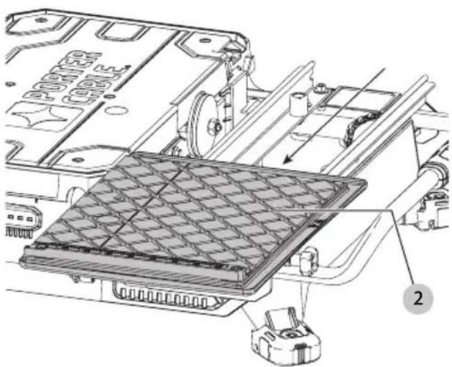
natural_image
Technical diagram of a mechanical assembly with labeled components (no readable text or symbols)English
- Install blade 13 onto the arbor 14. Ensure the blade is fully on the arbor 14 and fitted with the rotational direction matches the direction of the washer.
Fig. D
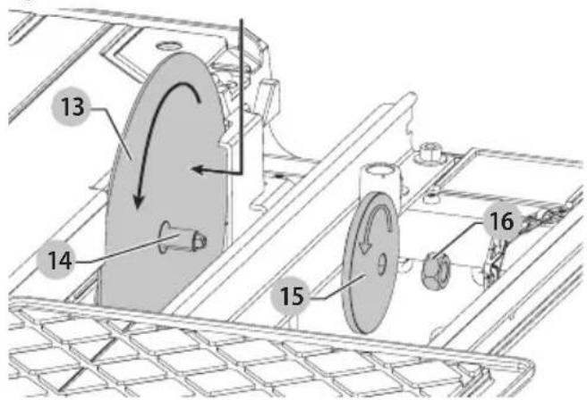
text_image
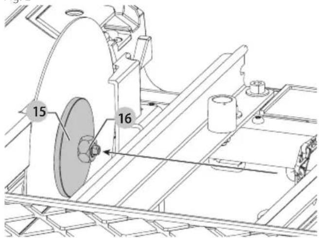
Technical diagram of a mechanical assembly with numbered components and directional arrows indicating motion or flow.- Install outer clamp washer 15 and blade nut 16. While holding blade in place, fully tighten blade nut with supplied wrench 4.
NOTE: Do not overtighten. Make sure the tile blade is secure before use.
Fig. E
text_image
15 16- Loosely install splash hood bracket 17 using the two supplied screws 18.
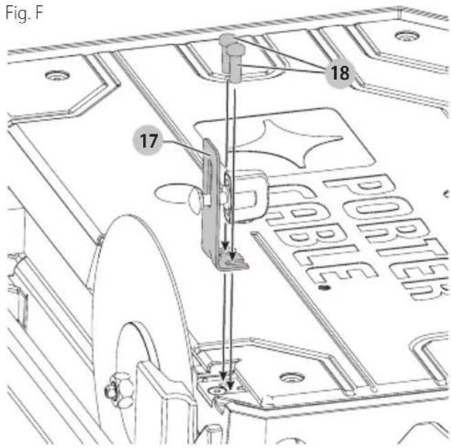
text_image
Fig. F 18 17 PORTER- Use supplied edge guide 7 to align bracket 17 and blade 13 as shown in Figure G. Once bracket is aligned, fully tighten hood bracket screws.
Fig. G
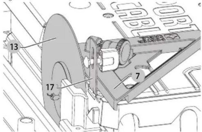
text_image
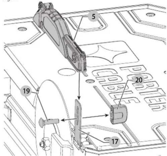
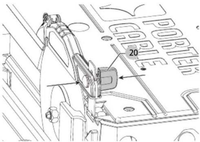
13 17 7 CABOLIC CABOLIC- Remove carriage bolt 19 and nut 20 from splash hood 5 and install splash hood onto the splash hood bracket. Insert carriage bolt through both the splash hood and bracket. Install and loosely tighten the nut 20. Adjust the height for your specific application. Fully tighten the nut 20.
Fig. H
text_image
5 19 20 17Fig.1
text_image
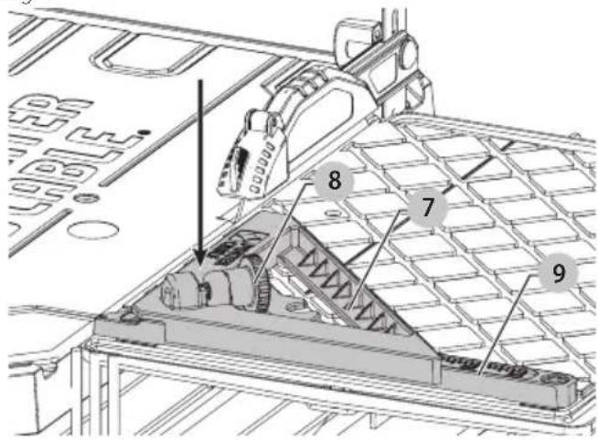
PORTED 20To Attach The Edge Guide (Fig. J)
The edge guide can be installed 1 of 2 ways, 45° or 90°.
-
Place edge gude 7 on the cutting cart fence 9..
-
Turn the edge guide lock 8 clockwise to tighten. Fig. J
text_image
Technical diagram of a mechanical assembly with numbered components, likely for engineering or manufacturing documentation.Specifications
| Voltage 20 V |
| RPM 2800 |
| Depth of Cut 1.25" (32 mm) |
| Blade Sizes 7" (178 mm) |
| Arbor Size 5/8" (16 mm) |
OPERATION
WARNING: To reduce the risk of serious personal injury, turn tool off and remove the battery pack before transporting, making any adjustments or removing/installing attachments or accessories.
An accidental start-up can cause injury. Make sure the switch is in the OFF position.
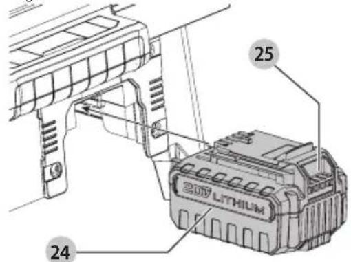
Installing and Removing the Battery Pack (Fig. K)
NOTE: For best results, make sure your battery pack is fully charged.
To install the battery pack 24 into the tool, align the battery pack with the rails on the side of the tool and slide it into the tool until the battery pack is firmly seated in the tool and ensure that it does not disengage.
To remove the battery pack from the tool, press the release button 25 and firmly pull the battery pack out of the tool. Insert it into the charger as described in the charger section of this manual.
Fig. K
text_image
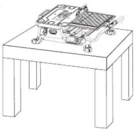
25 24Tool Placement (Fig. L)
Place saw on a stable, level surface.
Fig. L
natural_image
Line drawing of a mechanical device mounted on a four-legged table (no text or symbols)On/Off Switch (Fig. M)
• To turn the wet tile saw on, lift up the on/off switch 1.
• The wet tile saw locks on automatically.
• To turn the tool off, push the on/off switch down.
NOTE: A removable safety lock 26. can be removed to deter unauthorized use.
Fig. M
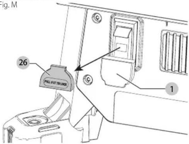
text_image
Fig. M 26 PULL OUT TO LOCK 1Filling and Draining the Water Reservoir (Fig. N)
- Plug the water reservoir drain hole 21 with the drain plug 22. Secure the drain plug into position by tightening the attached wing nut 23 as shown in Figure N.
- Slowly fill the water reservoir to the MIN fill line 30, to prevent accidental overfilling. Do not fill above the MAX fill line 31. (Fig N)
- To drain the reservoir, place a 5 gallon (19 liter) bucket under the drain plug.
- Remove the drain plug by loosening the attached wing nut and allow the water to empty into the bucket.
English
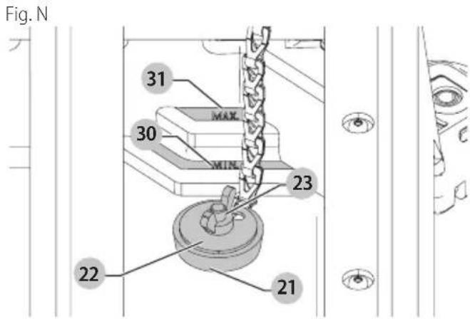
text_image
Fig. N 31 MAX 30 MIN 23 22 21Making a Cut (Fig. A)
Verify the proper alignment of the cutting cart and blade before turning the saw on.
Secure tile against the cart fence, or edge guide 7 with the edge guide lock 8. Always keep hands away from the blade.
- Pull up the on/off switch 1 to turn the saw on. Wait until the stream of water completely covers the blade.
nOTE: Cutting tile without water will damage the blade.
-
Ease the cutting cart toward the blade then slowly feed the tile into the blade. Continue pushing until the blade cuts completely through the tile.
-
Turn the saw off by pushing the on/off switch 1 down.
-
After the blade stops, remove the tile and remnant from the cutting cart.
Locking the Cutting Cart (Fig. 0)
There is one locking position for the cart. Move the cart to the lock position and lock the cart by pushing the pin 3 into a hole in the rail.
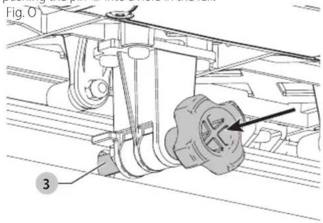
text_image
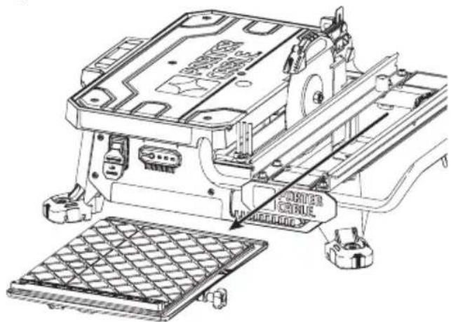
Fig. O 3Removal And Installation Of The Cutting Cart (Fig. A, P, Q)
To Remove The Cutting Cart
- Unlock the cutting cart stop 10.
- Slide the cutting cart off the tool.
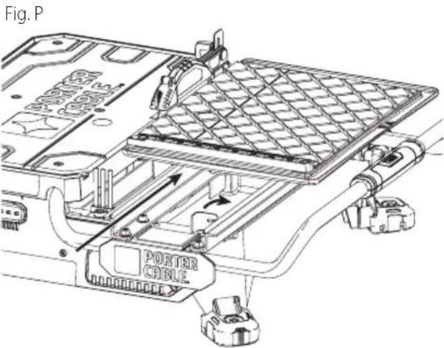
text_image
Fig. P PORTER CABLE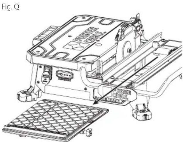
text_image
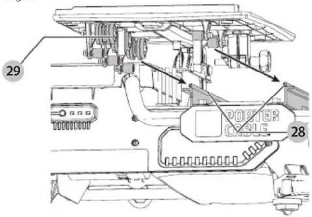
Fig. Q POWER CIRCLETo Install The Cutting Cart
- Align rail guide rollers 28 on the cutting cart to the rails 29 on the tool. Make sure the cutting cart lock pin is in the unlock position.
- Slide the cutting cart onto the tool.
- Lock the cutting cart stop.
Fig. R
text_image
29 POSTER CABLE 28Types of Cuts (Fig. A, S)
WARNING: Do not make freehand cuts.
Always do a practice run to acquaint yourself with the path of the blade. Practice on a scrap tile to ensure that you are comfortable with the feel of the cutting operation. Push the cart past the blade before turning the saw on.
Straight Cuts
- Using a marker or grease pencil, mark the area to be cut on tile.
- Place the tile on the cutting cart against the cutting cart fence 9 and align your mark with the blade.
- Pull the on/off switch up to turn the saw on and wait for the blade to be completely covered with water.
- Ease the cutting cart toward the blade then slowly feed the tile into the blade. Continue pushing until the blade cuts completely through the tile.
nOTE: The flip hood on the splash hood can be rotated up to help align the line on the tile with the blade. - Turn off the saw.
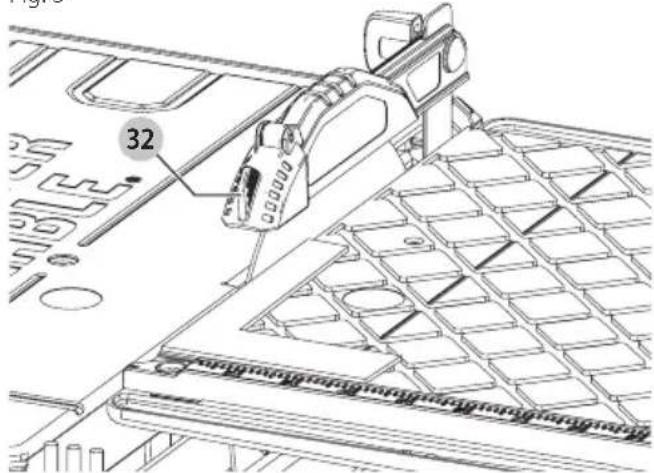
Diagonal Cuts
Diagonal cuts are also referred to as "long point to long point cuts."
- Install the edge guide.
- Align the point of the tile closest to the cutting cart fence 9 with the cut indicator 32.
- Align the front of the tile to the blade and hold against the edge guide.
- Turn the saw on and make the cut.
- Turn off the saw.
L-Cuts
An L-cut is a section that is removed from of a piece of tile and is used when cutting a piece of tile to fit in a corner of a cabinet or piece of trim molding.
- Outline the area to be cut on both sides of the tile.
- Align the tile to the cutting cart fence and make the cut far enough into the tile without overcutting.
- Make a cut on the other mark on the tile without overcutting.
- Turn the tile over and make the cut along one of the outlines, but this time an overcut can occur without damaging the exposed surface of the tile due to the radius of the blade. Overcut the other line and the cut piece should be separate from the rest of the tile.
- Turn off the saw.
Adjustments (Fig. A, S)
The cutting cart fence and rails are properly aligned from the factory. Shipping or prolonged use can cause them to become misaligned and need adjustment.
Squaring the Cutting Cart Fence to the Blade
- Lay a 90° square flat on the blade surface with one end against the cart fence 9.
- If the blade is not 90^ to the cart fence, the rail will need adjustment.
- Loosen the cart fence adjustment screw.
- Adjust the fence until it is square to the blade.
- Tighten the cart fence adjustment screw.
Adjusting the Cutting Cart Parallel to the Blade
- Lay a 90° square flat on the blade surface with one end against the cart fence 9.
Fig. S
text_image
32- If the blade is not 90^ to the cart fence, the rail will need adjustment.
- Loosen the three front and rear screws on the left guide rail, and adjust rail until it is parallel to the blade.
- Move the rail until the cart fence is square to the blade.
- Tighten the three rail screws.
MAINTENANCE
WARNING: To reduce the risk of serious personal injury, turn tool off and remove the battery pack before transporting, making any adjustments or removing/installing attachments or accessories.
An accidental start-up can cause injury. Make sure the switch is in the OFF position.
Lubrication
WARNING: NEVER spray or in any other way apply lantants or cleaning solvents inside the tool. This can seriously affect the life and performance of the tool and may result in personal injury.
PORTER-CABLE tools are properly lubricated at the factory and are ready for use. However, it is recommended that, once a year, you take or send the tool to a certified service center for a thorough cleaning and inspection.
Cleaning
WARNING: Blow dirt and dust out of all air vents with clean, dry air at least once a week. To minimize the risk of eye injury, always wear ANSI Z87.1 approved eye protection when performing this.
WARNING: Never use solvents or other harsh chemicals for cleaning the non-metallic parts of the tool. These chemicals may weaken the plastic materials used in these parts. Use a cloth dampened only with water and mild soap. Never let any liquid get inside the tool; never immerse any part of the tool into a liquid.
English
- Turn off and remove battery from the saw.
- Place a 5 gallon (19 liters) bucket under the drain plug. Remove the drain plug by loosening the attached wing nut and allow the water to empty into the bucket.
- Slide the cutting cart off the rail system. Spray the cutting cart with a hose or wipe with a grout sponge or rag.
- Wipe the rails with a grout sponge or a rag. Spray lubricants are not required on the guide rail or wheels.
- Clean the water reservoir by wiping with a grout sponge.
WARNING: Do not spray with water. Some water may reach the motor area.
Use only mild soap and a damp cloth to clean the tool. Many household cleaners contain chemicals which could seriously damage plastic. Also, do not use gasoline, turpentine, lacquer or paint thinner, dry cleaning fluids or similar products. Try not to let any liquid get inside the tool; never immerse any part of the tool into a liquid.
Accessories
WARNING: Since accessories, other than those offered by PORTER-CABLE, have not been tested with this product, use of such accessories with this tool could be hazardous. To reduce the risk of injury, only PORTER-CABLE recommended accessories should be used with this product.
A complete line of accessories is available from your PORTER-CABLE Factory Service Center or a PORTER-CABLE Authorized Warranty Service Center. Please visit our Web Site www.portercable.com for a catalog or for the name of your nearest supplier.
Blades
| 7" (178 mm) | Ceramic wheel |
| 7" (178 mm) | Porcelain wheel |
CAUTION: The use of any other accessory not recommended for use with this tool could be hazardous.
Repairs
The charger and battery pack are not serviceable.
WARNING: To assure product SAFETY and REELABILITY, repairs, maintenance and adjustment (including brush inspection and replacement, when applicable) should be performed by a PORTER-CABLE factory service center or a PORTER-CABLE authorized service center. Always use identical replacement parts.
Register Online
Thank you for your purchase. Register your product now for:
- WARAnTY sERViCE: Registering your product will help you obtain more efficient warranty service in case there is a problem with your product.
- COnFiRMATiOn OF OWnERshiP: In case of an insurance loss, such as fire, flood or theft, your registration of ownership will serve as your proof of purchase.
- FOR YOUR SAFETY: Registering your product will allow us to contact you in the unlikely event a safety notification is required under the Federal Consumer Safety Act.
Register online at www.portercable.com/register.
THREE YEAR LIMITED WARRANTY
PORTER-CABLE will repair or replace, without charge, any defects due to faulty materials or workmanship for three years from the date of purchase for tools (two years for batteries). This warranty does not cover part failure due to normal wear or tool abuse. For further detail of warranty coverage and warranty repair information, visit www.portercable.com or call (888) 848-5175. This warranty does not apply to accessories or damage caused where repairs have been made or attempted by others. This warranty gives you specific legal rights and you may have other rights which vary in certain states or provinces. In addition to the warranty, PORTER-CABLE tools are covered by our:
1 YEAR FREE SERVICE: PORTER-CABLE will maintain the tool and replace worn parts caused by normal use, for free, any time during the first year after purchase.
90 DAY MONEY BACK GUARANTEE: If you are not completely satisfied with the performance of your PORTER-CABLE Power Tool for any reason, you can return it within 90 days from the date of purchase with a receipt for a full refund – no questions asked.
LATIN AMERICA: This warranty does not apply to products sold in Latin America. For products sold in Latin America, see country specific warranty information contained in the packaging, call the local company or see website for warranty information.
To register your tool for warranty service visit our website at www.portercable.com.
WARning IABEI REPIACEMEnT
If your warning labels become illegible or are missing, call (888) 848-5175 for a free replacement.
PORTER CABLE.
4825 Highway 45 North
Jackson, Tennessee 38305
(888) 848-5175
www.portercable.com
Troubleshooting Guide
BE sURE TO FOLLOW SAFETY RULEs AnD insTRUCTiOns
For assistance with your product, visit our website at www.portercable.com for a list of service centers, or call the PORTER-CABLE Customer Care Center at (888) 848-5175.
| PROBLEM POSSIBLE CAUSE | POSSIBLE SOLUTION | |
| Unit will not start. Battery pack not installed properly | Battery pack not charged.Internal components too hot.Brushes worn out. | Check battery pack installationCheck battery pack charging requirements.Allow tool to cool down.Have brushes replaced by an authorized PORTER-CABLE service center. |
| Battery pack will not charge. Battery pack not inserted into charger.Charger not plugged in.Surrounding air temperature too hot or too cold. | Insert battery pack into charger until LED illuminates.Plug charger into a working outlet. Refer to Important Charging Notes for more details.Move charger and battery pack to a surrounding air temperature of above 40 °F (4.5 °C) or below 104 °F (+40 °C). | |
| Unit shuts off abruptly. Battery pack has reached its maximum thermal limit.Out of charge. (To maximize the life of the battery pack it is designed to shut off abruptly when the charge is depleted.) | Allow battery pack to cool down.Place on charger and allow to charge. | |
| Saw makes unsatisfactory cuts. Dull blade. | Not enough water in the tub.Blade mounted backwards.Build up on bladeIncorrect blade for work being done. | Replace blade.Check water level and add water if necessary.Turn blade around.Use dressing stone to remove build up.Change the blade. |
| Unit does not make accurate cuts. Edge guide not secure to fence. | Blade is not square to fence.Blade is not perpendicular to cart surface.Workpiece moving. | Check and adjust.Check and adjust.Check and adjust fence.Use edge guide. |
| Unit vibrates excessively. Saw not mounted on a level surface. | Damaged saw blade. | Reposition on a level surface.Replace blade. |
| Blade does not come up to speed. Arbor loose. Tighten arbor. |
text_image
Technical diagram of a portable electronic device with numbered components and labeled parts in Chinesenatural_image
Technical diagram of a mechanical assembly with labeled components (no readable text or symbols)FRAnÇAis
text_image
Technical diagram of a mechanical assembly with numbered components and directional arrows indicating motion or flow.text_image
Technical diagram of a mechanical assembly with numbered components, likely for engineering or manufacturing documentation.natural_image
Line drawing of a mechanical device mounted on a stand (no text or symbols)4825 Highway 45 North
Jackson, Tennessee 38305
888-848-5175
www.portercable.com
Guide de dépannage
s'AssURER DE sUiVRE TOUTEs IEs DiRECTiVEs, Y COMPRis IEs COnsignEs DE sÉCURiTÉ
text_image
Technical diagram of a device with numbered components and exploded view, highlighting ports like USB port and cable assembly.natural_image
Technical diagram of an internal device with labeled components, showing a grid-patterned panel and mechanical parts (no text or symbols present)text_image
Technical diagram of a mechanical assembly with numbered components and directional arrows indicating motion or flow.text_image
Technical diagram of a mechanical assembly with numbered components, likely for engineering or manufacturing documentation.Especificaciones
Voltaje 20 V
RPM 2800
natural_image
Line drawing of a mechanical device mounted on a four-legged table (no text or symbols)text_image
PORTER ORIBLEFig. Q
natural_image
Technical line drawing of a mechanical assembly with labeled components (no readable text or symbols)Eje Central Lázaro Cárdenas No. 18 - Local (55) 5588 9377 D, Col. Obrera
MERIDA, YUC
Calle 63 #459-A - Col. Centro (999) 928 5038
MONTERREY, N.L.
Av. Francisco I. Madero 831 Poniente - Col. (818) 375 23 13 Centro
PUEBLA, PUE
17 Norte #205 - Col. Centro (222) 246 3714
QUERETARO, QRO
Av. San Roque 274 - Col. San Gregorio (442) 2 17 63 14
ESPAÑOL
SAN LUIS POTOSI, SLP
4825 Highway 45 North
Jackson, Tennessee 38305
(888) 848-5175
www.portercable.com
EsPECiFiCACiOnEs
PCC780 20 V Máx* 2800 rpm