PCE980 - Saw Porter-Cable - Free user manual and instructions
Find the device manual for free PCE980 Porter-Cable in PDF.
| Product Type | Tile Saw (wet) |
| Brand | Porter-Cable |
| Model | PCE980 |
| Rated Voltage | 120 V |
| Rated Amperage | 6.5 A |
| No-load Speed | 3600 rpm |
| Maximum Cutting Depth | 32 mm (1.25 in) |
| Compatible Blade Diameter | 178 mm (7 in) |
| Arbor Diameter | 16 mm (5/8 in) |
| Power Source | Mains (cord with grounding plug) |
| Cut Type | Straight, diagonal, and L-shaped cuts |
| Cooling System | Water (integrated tank) |
| Safety Devices | Splash guard, emergency stop, carriage lock |
| Recommended Maintenance | Regular cleaning of vents and tank, drain water after use |
| Included Accessories | Wrench, splash guard, edge guide |
| Warranty | Limited 3-year (tool) / 2-year (battery packs) / 1-year free service |
Frequently Asked Questions - PCE980 Porter-Cable
User questions about PCE980 Porter-Cable
0 question about this device. Answer the ones you know or ask your own.
Ask a new question about this device
Download the instructions for your Saw in PDF format for free! Find your manual PCE980 - Porter-Cable and take your electronic device back in hand. On this page are published all the documents necessary for the use of your device. PCE980 by Porter-Cable.
USER MANUAL PCE980 Porter-Cable
Thank you for choosing PORTER-CABLE! To register your new product, go to:
www.portercable.com/ServiceAndSupport/ProductRegistration.aspx
Definitions: Safety Alert Symbols and Words
This instruction manual uses the following safety alert symbols and words to alert you to hazardous situations and your risk of personal injury or property damage.
DANGER: Indicates an imminently hazardous situation which, if not avoided, will result in death or serious injury.
WARNING: Indicates a potentially hazardous situation which, if not avoided, could result in death or serious injury.
CAUTION: Indicates a potentially hazardous situation which, if not avoided, may result in minor or moderate injury.
(### without word) Indicates a safety related message.
NOTICE: Indicates a practice not related to personal injury which, if not avoided, may result in property damage.
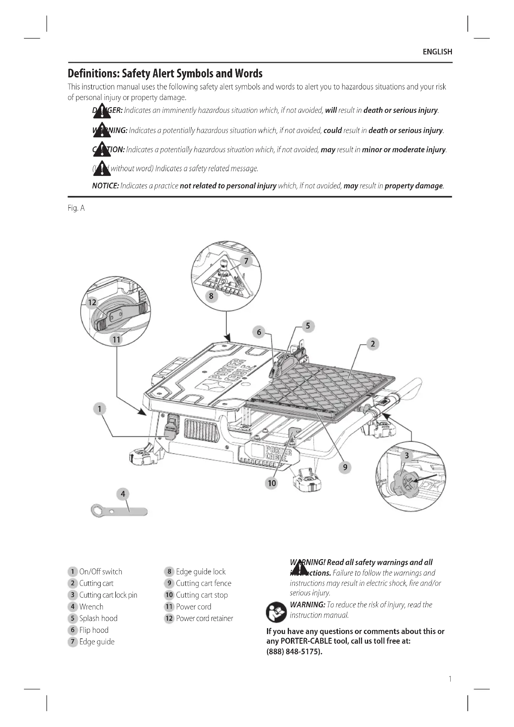
Fig. A
text_image
Technical diagram of a device with numbered components and labeled parts, including a motor and cable assembly.1 On/Off switch
2 Cutting cart
3 Cutting cart lock pin
4 Wrench
5 Splash hood
6 Flip hood
7 Edge guide
8 Edge guide lock
9 Cutting cart fence
10 Cutting cart stop
11 Power cord
12 Power cord retainer
WARNING! Read all safety warnings and all
instructions. Failure to follow the warnings and instructions may result in electric shock, fire and/or serious injury.

WARNING: To reduce the risk of injury, read the instruction manual.
If you have any questions or comments about this or any PORTER-CABLE tool, call us toll free at: (888) 848-5175).
English
GENERAL POWER TOOL SAFETY WARNINGS
WARNING! Read all safety warnings and all instructions. Failure to follow the warnings and instructions may result in electric shock, fire and/or serious injury.
SAVE ALL WARNINGS AND INSTRUCTIONS FOR FUTURE REFERENCE
The term "power tool" in the warnings refers to your mains-operated (corded) power tool or battery-operated (cordless) power tool.
WARNING: Never use saw with salt water or a conductive fluid.
WARNING: when using electric tools, basic safety precautions should always be followed to reduce risk of fire, electric shock, and personal injury, including the following:
- KEEP GUARDS IN PLACE and in working order.
- REMOVE ADJUSTING KEYS AND WRENCHES. Form habit of checking to see that keys and adjusting wrenches are removed from tool before turning it on.
- KEEP WORK AREA CLEAN. Cluttered areas and benches invite injuries.
- DON'T USE IN DANGEROUS ENVIRONMENT. Don't use power tools in damp or wet locations, or expose them to rain or snow. Keep work area well lighted.
- KEEP CHILDREN AWAY. All visitors should be kept safe distance from work area.
- MAKE WORKSHOP KID PROOF with padlocks, master switches, or by removing starter keys.
- DON'T FORCE TOOL. It will do the job better and safer at the rate for which it was designed.
- USE RIGHT TOOL. Don't force tool or attachment to do a job for which it was not designed
- USE PROPER EXTENSION CORD. Make sure your extension cord is in good condition. When using an extension cord, be sure to use one heavy enough to carry the current your product will draw. An undersized cord will cause a drop in line voltage resulting in loss of power and overheating. The following table shows the correct size to use depending on cord length and nameplate ampere rating. If in doubt, use the next heavier gage. The smaller the gage number, the heavier the cord.
- WEAR PROPER APPAREL. Do not wear loose clothing, gloves, neckties, rings, bracelets, or other jewelry which may get caught in moving parts. Nonslip footwear is recommended. Wear protective hair covering to contain long hair. Air vents often cover moving parts and should also be avoided.
- ALWAYS USE SAFETY GLASSES. Also use face or dust mask if cutting operation is dusty. Everyday eyeglasses only have impact resistant lenses, they are not safety glasses.
-
SECURE WORK. Always place tile flat on cart and securely against fence.
-
NEVER USE A PAN HEATER OR OTHER HEAT SOURCE FOR HEATING WATER. Damage to the tool, fire or personal injury could result.
- DON'T OVERREACH. Keep proper footing and balance at all times.
- MAINTAIN TOOLS WITH CARE. Keep tools sharp and clean for best and safest performance. Follow instructions for lubricating and changing accessories.
- DISCONNECT TOOLS before servicing; when changing accessories, such as cutting wheels, clamps, extensions, and the like.
- REDUCE THE RISK OF UNINTENTIONAL STARTING. Make sure switch is in off position before plugging in
- USE RECOMMENDED ACCESSORIES. Consult the instruction manual for recommended accessories. The use of improper accessories may cause risk of injury to persons.
- NEVER STAND ON TOOL. Serious injury could occur if the tool is tipped or if the cutting tool is unintentionally contacted.
- CHECK DAMAGED PARTS. Before further use of the tool, a guard or other part that is damaged should be carefully checked to determine that it will operate properly and perform its intended function—check for alignment of moving parts, binding of moving parts, breakage of parts, mounting, and any other conditions that may affect its operation. A guard or other part that is damaged should be properly repaired or replaced.
- DIRECTION OF FEED. Feed work into a cutting wheel with the direction of rotation only.
- NEVER LEAVE TOOL RUNNING UNATTENDED. TURN POWER OFF. Don't leave tool until it comes to a complete stop.
- REPLACEMENT PARTS. When servicing, use only identical replacement parts.
Grounding Instructions
- In the event of a malfunction or breakdown, grounding provides a path of least resistance for electric current to reduce the risk of electric shock. This tool is equipped with an electric cord having an equipment-grounding conductor and a grounding plug. The plug must be plugged into a matching outlet that is properly installed and grounded in accordance with all local codes and ordinances.
- Do not modify the plug provided – if it will not fit the outlet, have the proper outlet installed by a qualified electrician.
- Improper connection of the equipment-grounding conductor can result in a risk of electric shock. The conductor with insulation having an outer surface that is green with or without yellow stripes is the equipment-grounding conductor. If repair or replacement of the electric cord or plug is necessary, do not connect the equipment-grounding conductor to a live terminal.
- Check with a qualified electrician or service personnel if the grounding instructions are not completely understood, or if in doubt as to whether the tool is properly grounded.
- Use only 3-wire extension cords that have 3-prong grounding plugs and 3-pole receptacles that accept the tool's plug.
• Repair or replace damaged or worn cord immediately.
This tool should be grounded while in use to protect the operator from electric shock. The tool is equipped with a
English
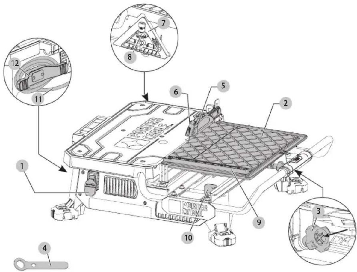
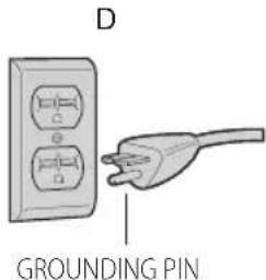
3-conductor cord and 3-prong grounding type plug to fit the proper grounding type receptacle. The green (or green and yellow) conductor in the cord is the grounding wire. Never connect the green (or green and yellow) wire to a live terminal. If your unit is intended for use on less than 150 V, it has a plug that looks like that shown in sketch A. If it is for use on 150 to 250 V, it has a plug that looks like that shown in sketch D. An adapter, sketches B and C, is available for connecting sketch A type plugs to 2-prong receptacles. The green-colored rigid ear, lug, or the like, extending from the adapter must be connected to a permanent ground, such as a properly grounded outlet box. No adapter is available for a plug as shown in sketch D. ADAPTER SHOWN IN SKETCHES B and C ARE NOT FOR USE IN CANADA.
Fig. B
text_image
A GROUNDED OUTLET BOX GROUNDING PIN B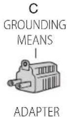
text_image
D GROUNDING PINWARNING: To reduce the risk of electrocution, keep all actions dry and off the ground. Do not touch the plug with wet hands.
WARNING: The saw must be plugged into a GFCI p-adited receptacle.
WARNING: Never use saw with salt water or a conductive fluid.
Additional Safety Rules for Wet Tile Saw
CAUTION: Wear appropriate hearing protection during use. Under some conditions and duration of use, noise from this product may contribute to hearing loss.
CAUTION: Do not connect unit to electrical power source until complete instructions are read and understood.
- Use safety equipment. Always wear eye protection. Dust mask, non-skid safety shoes, hard hat, or hearing protection must be used for appropriate conditions.
- Keep hands out of path of saw blade. NEVER CUT A PIECE WHERE HAND WOULD BE 3" (76 mm) OR LESS FROM BLADE.
-
Do not perform any operation freehand, that is without holding the workpiece firmly against the fence or edge guide.
• Never reach in back of the blade. -
DON'T - Cut dry. If blade is not cooled with water, serious damage will occur. Dry cutting will increase exposure to harmful airborne dust.
- Turn off the tool and wait for blade to stop before moving the workpiece or changing settings.
• To reduce risk of injury, return the cart to the full rear position after each cut. - DO - Make certain the blade rotates in the correct direction as indicated by the arrow on the blade.
• DO - Always use the splash hood. - DO - Be sure all clamp handles and knobs are tight before starting any operation.
- DO - Be sure all blade and clamp washers are clean and recessed sides of collars are against blade. Tighten arbor nut securely.
• DO - Keep the blade properly aligned. - DO - Keep the motor air slots free of chips and dirt.
- DO - Always empty water from the reservoir before transporting. Water can splash into electrical components.
• DO - Keep hands out of the path of the saw blade. - DON'T - Attempt to operate on anything but designated voltage. Incorrect voltage may result in shock, fire, or unpredictable operation.
- DON'T - Use blades larger or smaller than those which are recommended.
- DON'T - Force cutting action. Allow motor to reach full speed before cutting. Stalling or partial stalling of motor can cause major damage.
- DON'T - Use metal cutting abrasive wheels. The excessive heat and abrasive particles generated by them will damage the saw.
- DO - Use continuous rim wheels only, no serrated edges or toothed blades.
• DON'T - Allow anyone to stand behind saw. - DON'T - Place either hand in the blade area when the saw is connected to the power source.
• DON'T - Use blades rated less than 5000 R.P.M. - DON'T - Place hands closer than 3" (76 mm) from the saw blade.
- DON'T - Reach behind or underneath the saw unless it is turned off and unplugged.
- DON'T - Move either hand from saw or workpiece until the blade has stopped.
Additional Safety Information
WARNING: ALWAYS use safety glasses. Everyday eyeglasses are NOT safety glasses. Also use face or dust mask if cutting operation is dusty. ALWAYS WEAR CERTIFIED SAFETY EQUIPMENT:
• ANSI Z87.1 eye protection (CAN/CSA Z94.3),
• ANSI S12.6 (S3.19) hearing protection,
• NIOSH/OSHA/MSHA respiratory protection.
WARNING: Some dust created by power sanding, sawing, grinding, drilling, and other construction activities contains chemicals known to the State of California to cause cancer, birth defects or
ENGLISH
other reproductive harm. Some examples of these chemicals are:
- lead from lead-based paints,
• crystalline silica from bricks and cement and other masonry products, and
• arsenic and chromium from chemically-treated lumber.
Your risk from these exposures varies, depending on how often you do this type of work. To reduce your exposure to these chemicals: work in a well ventilated area, and work with approved safety equipment, such as those dust masks that are specially designed to filter out microscopic particles.
- Avoid prolonged contact with dust from power sanding, sawing, grinding, drilling, and other construction activities. Wear protective clothing and wash exposed areas with soap and water. Allowing dust to get into your mouth, eyes, or lay on the skin may promote absorption of harmful chemicals.
WARNING: Use of this tool can generate and/perse dust, which may cause serious and permanent respiratory or other injury. Always use NIOSH/OSHA approved respiratory protection appropriate for the dust exposure. Direct particles away from face and body.
WARNING: Always wear proper personal hearing protection that conforms to ANSI S12.6 (S3.19)
during use. Under some conditions and duration of use, noise from this product may contribute to hearing loss.
• Air vents often cover moving parts and should be avoided. Loose clothes, jewelry or long hair can be caught in moving parts.
- An extension cord must have adequate wire size (AWG or American Wire Gauge) for safety. The smaller the gauge number of the wire, the greater the capacity of the cable, that is, 16 gauge has more capacity than 18 gauge. An undersized cord will cause a drop in line voltage resulting in loss of power and overheating. When using more than one extension to make up the total length, be sure each individual extension contains at least the minimum wire size. The following table shows the correct size to use depending on cord length and nameplate ampere rating. If in doubt, use the next heavier gauge. The lower the gauge number, the heavier the cord.
Minimum Gauge for Cord Sets
| Volts | Total Length of Cord in Feet (meters) | ||||
| 120 V 25 (7.6) | 50 (15.2) | 100 (30.5) | 150 (45.7) | ||
| 240 V 50 (15.2) | 100 (30.5) | 200 (61.0) | 300 (91.4) | ||
| Ampere Rating | American Wire Gauge | ||||
| More Than | Not More Than | ||||
| 0 6 18 | 16 16 14 | ||||
| 6 10 | 18 16 14 12 | ||||
| 10 12 | 16 16 14 12 | ||||
| 12 16 | 14 12 Not Recommended | ||||
The label on your tool may include the following symbols. The symbols and their definitions are as follows:
V....volts
min......minutes
Hz......hertz
= - - - or DC.....direct current
Class I Construction (grounded)
.../min.....per minute
BPM.....beats per minute
IPM....impacts per minute
RPM......revolutionsper minute
sfpm .... surface feet per minute
SPM ...... strokes per minute
A.....amperes
W.....watts
\~ or AC......alternating current
or AC/DC....alternatingor direct current
ClassII
Construction
(double insulated)
n_0 ......no load speed
n ......rated speed
± earthing terminal
⚠️ ......safety alert symbol
△......visible radiation
......wearrespiratory protection
Weareye
protection
O....wearhearing
protection
readall documentation
SAVE THESE INSTRUCTIONS FOR FUTURE USE
Motor
Be sure your power supply agrees with the nameplate marking. Voltage decrease of more than 10% will cause loss of power and overheating. PORTER-CABLE tools are factory tested; if this tool does not operate, check power supply.
COMPONENTS (FIG. A)
WARNING: Never modify the power tool or any part of it. Damage or personal injury could result.
Refer to Figure A at the beginning of this manual for a complete list of components.
INTENDED USE
This wet tile saw is designed for cutting a variety of tile and other tile type applications.
DO NOT cut wood, metals or plastics.
DO NOT use under wet conditions or in presence of flammable liquids or gases.
DO NOT let children come into contact with the tool. Supervision is required when inexperienced operators use this tool.
ASSEMBLY AND ADJUSTMENTS
WARNING: To reduce the risk of serious personal injury, turn unit off and disconnect it from
power source before making any adjustments or removing/installing attachments or accessories.
An accidental start-up can cause injury. Make sure the switch is in the OFF position.
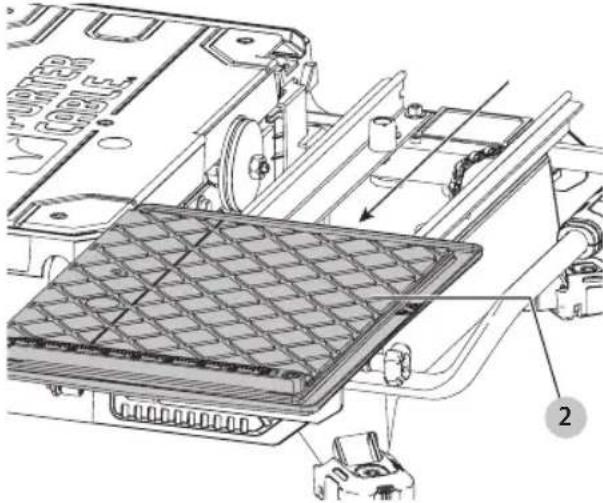
Assembly (Fig. A, C–I)
- Place the tool on a stable surface.
- Unlock cutting cart 2 by pulling out on the cutting cart lock pin 3 and slide the cutting cart back to reveal the blade housing.
English
Fig. C
natural_image
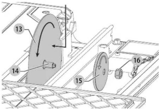
Technical diagram of a mechanical assembly with labeled components (no readable text or symbols)- Install blade 13 onto the arbor 14. Ensure the blade is fully on the arbor 14 and fitted with the rotational direction matches the direction of the washer.
Fig. D
text_image
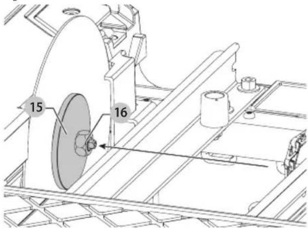
13 14 15 16- Install outer clamp washer 15 and blade nut 16. While holding blade in place, fully tighten blade nut with supplied wrench 4.
nOTE: Do not overtighten. Make sure the tile blade is secure before use.
Fig. E
text_image
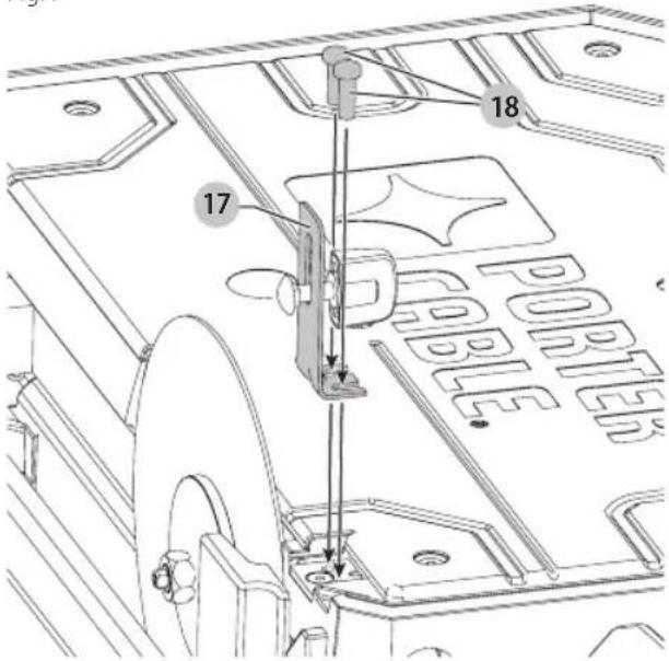
15 16- Loosely install splash hood bracket 17 using the two supplied screws 18.
Fig. F
text_image
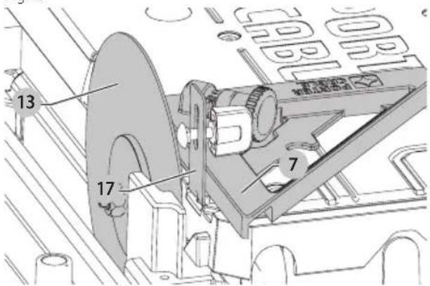
17 18 PORTER- Use supplied edge guide 7 to align bracket 17 and blade 13 as shown in Figure G. Once bracket is aligned, fully tighten hood bracket screws.
Fig. G
text_image
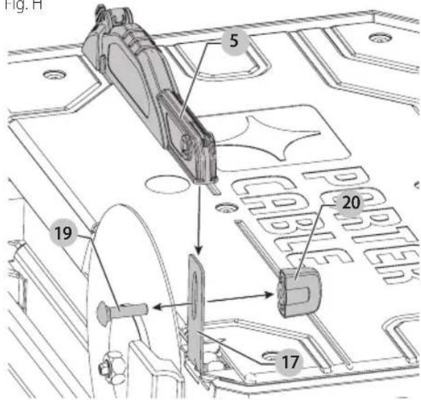
13 17 7- Remove carriage bolt 19 and nut 20 from splash hood 5 and install splash hood onto the splash hood bracket. Insert carriage bolt through both the splash hood and bracket. Install and loosely tighten the nut 20. Adjust the height for your specific application. Fully tighten the nut 20.
Fig. H
text_image
Fig. H 5 20 19 17English
Fig.1
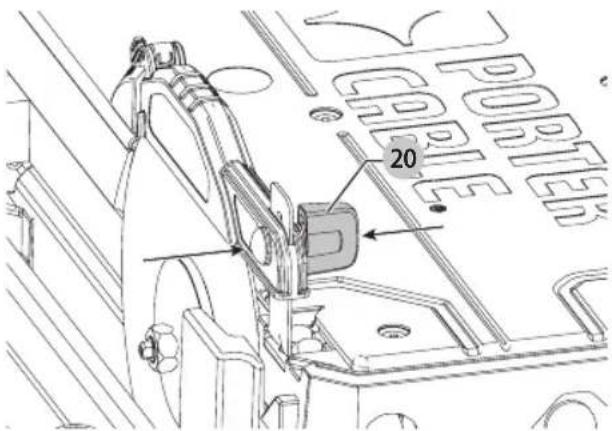
text_image
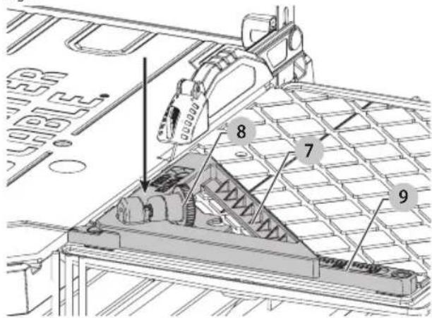
PORTER 20To Attach The Edge Guide (Fig. J)
The edge guide can be installed 1 of 2 ways, 45° or 90°.
- Place edge gude 7 on the cutting cart fence 9 ..
- Turn the edge guide lock 8 clockwise to tighten.
Fig. J
text_image
Technical diagram of a mechanical assembly with numbered components, likely for engineering or manufacturing documentation.Specifications
Voltage 120 V
Amps 6.5A
RPM 3600
Depth of Cut 1.25" (32 mm)
Blade Sizes 7" (178 mm)
Arbor Size 5/8" (16 mm)
OPERATION
WARNING: To reduce the risk of serious personal injury, turn unit off and disconnect it from power source before making any adjustments or removing/installing attachments or accessories.
An accidental start-up can cause injury. Make sure the switch is in the OFF position.
Tool Placement (Fig. K)
Place saw on a stable, level surface.
Fig. K
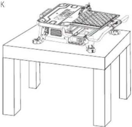
natural_image
Line drawing of a mechanical device mounted on a stand, showing internal components and mounting brackets (no text or symbols)Fig. L
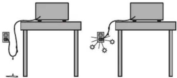
natural_image
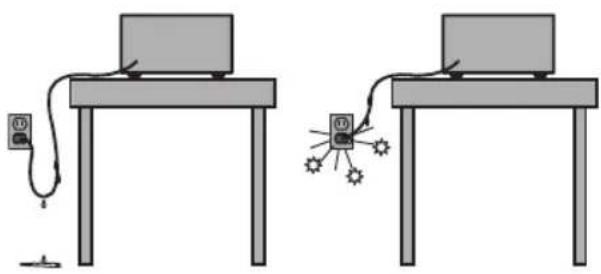
Two identical diagrams of a computer setup with connected devices and a central display (no text or symbols)On/Off Switch (Fig. L, M)
WARNING: To avoid the possibility of the appliance plug or receptacle getting wet, position the wet tile saw to one side of a wall mounted receptacle to prevent water from dipping onto the receptacle or plug. The user should arrange a "drip loop" in the cord connecting the saw to a receptacle (Fig. L). The "drip loop" is that part of the cord below the level of the receptacle, or the connector if an extension cord is used, to prevent water traveling along the cord and coming in contact with the receptacle. Always plug the saw into a GFCI receptacle and test to confirm the GFCI is operating properly. If the plug or receptacle does get wet, DON'T unplug the cord. Disconnect the fuse or circuit breaker that supplies power to the tool. Then unplug and examine for presence of water in the receptacle.
To turn the wet tile saw on, lift up the on/off switch 1. The wet tile saw locks on automatically.
To turn the tool off, push the on/off switch down.
NOTE: A removable safety lock 26. can be removed to deter unauthorized use.
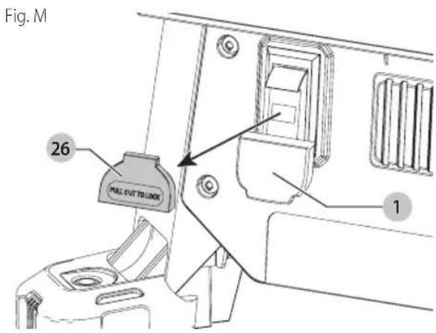
text_image
Fig. M 26 PULL CUT TO LOCK 1Filling and Draining the Water Reservoir (Fig. N)
- Plug the water reservoir drain hole 21 with the drain plug 22. Secure the drain plug into position by tightening the attached wing nut 23 as shown in Figure N.
- Slowly fill the water reservoir to the MIN fill line 24, to prevent accidental overfilling. Do not fill above the MAX fill line 25. (Fig. N)
- To drain the reservoir, place a 5 gallon (19 liter) bucket under the drain plug.
- Remove the drain plug by loosening the attached wing nut and allow the water to empty into the bucket.
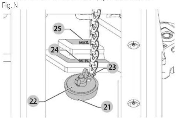
text_image
Fig. N 25 MAX 24 MIN 23 22 21Making a Cut (Fig. A)
Verify the proper alignment of the cutting cart and blade before turning the saw on.
Secure tile against the cart fence, or edge guide 7 with the edge guide lock 8. Always keep hands away from the blade.
- Pull up the on/off switch 1 to turn the saw on. Wait until the stream of water completely covers the blade.
NOTE: Cutting tile without water will damage the cutting wheel.
- Ease the cutting cart toward the blade then slowly feed the tile into the blade. Continue pushing until the blade cuts completely through the tile.
- Turn the saw off by pushing the on/off switch 1 down.
- After the blade stops, remove the tile and remnant from the cutting cart.
Locking the Cutting Cart (Fig. 0)
There is one locking position for the cart.
Move the cart to the lock position and lock the cart by pushing the pin 3 into a hole in the rail.
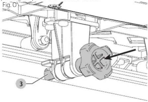
text_image
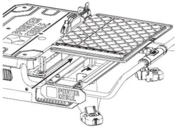
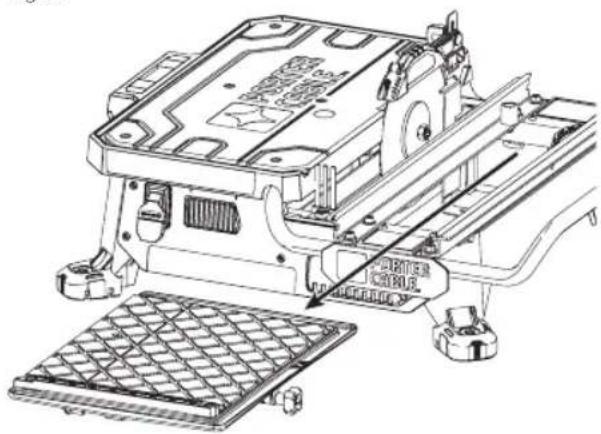
Fig. O 3Removal and Installation of the Cutting Cart (Fig. A, P, Q)
To Remove the Cutting Cart
- Unlock the cutting cart stop 10 .
- Slide the cutting cart off the tool.
Fig. P
text_image
PORTER CABLE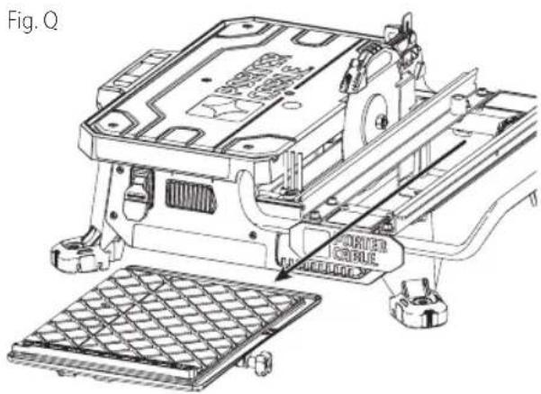
natural_image
Technical line drawing of an electronic device with a grid base and mechanical components (no text or symbols)English
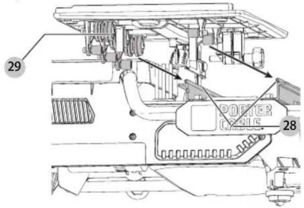
To Install the Cutting Cart
- Align rail guide rollers 28 on the cutting cart to the rails 29 on the tool. Make sure the cutting cart lock pin is in the unlock position.
- Slide the cutting cart onto the tool.
- Lock the cutting cart stop.
Fig. R
text_image
29 POSTER CABLE 28Types of Cuts (Fig. A, S)
Always do a practice run to acquaint yourself with the path of the blade. Practice on a scrap tile to ensure that you are comfortable with the feel of the cutting operation. Push the cart past the blade before turning the saw on.
Straight Cuts
- Using a marker or grease pencil, mark the area to be cut on tile.
- Place the tile on the cutting cart against the cutting cart fence 9 and align your mark with the blade.
- Pull the on/off switch up to turn the saw on and wait for the blade to be completely covered with water.
- Ease the cutting cart toward the blade then slowly feed the tile into the blade. Continue pushing until the blade cuts completely through the tile.
NOTE: The flip hood on the splash hood can be rotated up to help align the line on the tile with the blade. - Turn off the saw.
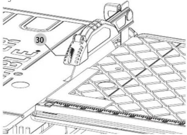
Diagonal Cuts
Diagonal cuts are also referred to as "long point to long point cuts."
- Install the edge guide.
- Align the point of the tile closest to the cutting cart fence 9 with the cut indicator 30.
- Align the front of the tile to the blade and hold against the edge guide.
- Turn the saw on and make the cut.
- Turn off the saw.
L-Cuts
An L-cut is a section that is removed from of a piece of tile and is used when cutting a piece of tile to fit in a corner of a cabinet or piece of trim molding.
- Outline the area to be cut on both sides of the tile.
-
Align the tile to the cutting cart fence and make the cut far enough into the tile without overcutting.
-
Make a cut on the other mark on the tile without overcutting.
- Turn the tile over and make the cut along one of the outlines, but this time an overcut can occur without damaging the exposed surface of the tile due to the radius of the blade. Overcut the other line and the cut piece should be separate from the rest of the tile.
- Turn off the saw.
Adjustments (Fig. A, S)
The cutting cart fence and rails are properly aligned from the factory. Shipping or prolonged use can cause them to become misaligned and need adjustment.
Squaring the Cutting Cart Fence to the Blade
- Lay a 90° square flat on the blade surface with one end against the cart fence 9.
- If the blade is not 90^ to the cart fence, the rail will need adjustment.
- Loosen the cart fence adjustment screw.
- Adjust the fence until it is square to the blade.
- Tighten the cart fence adjustment screw.
Adjusting the Cutting Cart Parallel to the Blade
- Lay a 90° square flat on the blade surface with one end against the cart fence 9.
Fig. S
text_image
30- If the blade is not 90° to the cart fence, the rail will need adjustment.
- Loosen the three front and rear screws on the left guide rail, and adjust rail until it is parallel to the blade..
- Move the rail until the cart fence is square to the blade.
- Tighten the three rail screws.
MAINTENANCE
WARNING: To reduce the risk of serious personal injury, turn unit off and disconnect it from power source before making any adjustments or removing/installing attachments or accessories. An accidental start-up can cause injury.
Lubrication
WARNING: NEVER spray or in any other way apply lachants or cleaning solvents inside the tool. This can seriously affect the life and performance of the tool and may result in personal injury.
PORTER-CABLE tools are properly lubricated at the factory and are ready for use. However, it is recommended that, once a year, you take or send the tool to a certified service center for a thorough cleaning and inspection.
Cleaning
WARNING: Blow dirt and dust out of all air vents with clean, dry air at least once a week. To minimize the risk of eye injury, always wear ANSI Z87.1 approved eye protection when performing this.
WARNING: Never use solvents or other harsh chemicals for cleaning the non-metallic parts of the tool. These chemicals may weaken the plastic materials used in these parts. Use a cloth dampened only with water and mild soap. Never let any liquid get inside the tool; never immerse any part of the tool into a liquid.
- Turn off and remove battery from the saw.
- Place a 5 gallon (19 liter) bucket under the drain plug. Remove the drain plug by loosening the attached wing nut and allow the water to empty into the bucket.
- Slide the cutting cart off the rail system. Spray the cutting cart with a hose or wipe with a grout sponge or rag.
- Wipe the rails with a grout sponge or a rag. Spray lubricants are not required on the guide rail or wheels.
- Clean the water reservoir by wiping with a grout sponge.
WARNING: Do not spray with water. Some water may reach the motor area.
Use only mild soap and a damp cloth to clean the tool. Many household cleaners contain chemicals which could seriously damage plastic. Also, do not use gasoline, turpentine, lacquer or paint thinner, dry cleaning fluids or similar products. Try not to let any liquid get inside the tool; never immerse any part of the tool into a liquid.
Accessories
WARNING: Since accessories, other than those offered by PORTER-CABLE, have not been tested with this product, use of such accessories with this tool could be hazardous. To reduce the risk of injury, only PORTER-CABLE recommended accessories should be used with this product.
A complete line of accessories is available from your PORTER-CABLE Factory Service Center or a PORTER-CABLE Authorized Warranty Service Center. Please visit our Web Site www.portercable.com for a catalog or for the name of your nearest supplier.
Blades
7" (178 mm) Ceramic wheel
7" (178 mm) Porcelain wheel
CAUTION: The use of any other accessory not recommended for use with this tool could be hazardous.
Repairs
WARNING: To assure product SAFETY and RUBILITY, repairs, maintenance and adjustment (including brush inspection and replacement, when applicable) should be performed by a PORTER-CABLE factory service center or a PORTER-CABLE authorized service center. Always use identical replacement parts.
Register Online
Thank you for your purchase. Register your product now for:
- WARRAnTY sERViCE: Registering your product will help you obtain more efficient warranty service in case there is a problem with your product.
- COnFiRMATiOn OF OWnERshiP: In case of an insurance loss, such as fire, flood or theft, your registration of ownership will serve as your proof of purchase.
- FOR YOUR SAFETY: Registering your product will allow us to contact you in the unlikely event a safety notification is required under the Federal Consumer Safety Act.
Register online at www.portercable.com/register.
THREE YEAR LIMITED WARRANTY
PORTER-CABLE will repair or replace, without charge, any defects due to faulty materials or workmanship for three years from the date of purchase for tools (two years for batteries). This warranty does not cover part failure due to normal wear or tool abuse. For further detail of warranty coverage and warranty repair information, visit www.portercable.com or call (888) 848-5175. This warranty does not apply to accessories or damage caused where repairs have been made or attempted by others. This warranty gives you specific legal rights and you may have other rights which vary in certain states or provinces.
In addition to the warranty, PORTER-CABLE tools are covered by our:
1 YEAR FREE SERVICE: PORTER-CABLE will maintain the tool and replace worn parts caused by normal use, for free, any time during the first year after purchase.
90 DAY MONEY BACK GUARANTEE: If you are not completely satisfied with the performance of your PORTER-CABLE Power Tool for any reason, you can return it within 90 days from the date of purchase with a receipt for a full refund – no questions asked.
LATIN AMERICA: This warranty does not apply to products sold in Latin America. For products sold in Latin America, see country specific warranty information contained in the packaging, call the local company or see website for warranty information.
To register your tool for warranty service visit our website at www.portercable.com.
English
WARning IABEI REPIACEMEnT
If your warning labels become illegible or are missing, call
(888) 848-5175 for a free replacement.
PORTER CABLE.
4825 Highway 45 North
Jackson, Tennessee 38305
(888) 848-5175
www.portercable.com
Troubleshooting Guide
BE sURE TO FOLLOW SAFETY RULEs AnD insTRUCTiOns
For assistance with your product, visit our website at www.portercable.com for a list of service centers, or call the PORTER-CABLE Customer Care Center at (888) 848-5175.
| PROBLEM POSSIBLE CAUSE | POSSIBLE SOLUTION | |
| Unit will not start. Cord is not plugged in. | Circuit fuse is blown.Circuit breaker is tripped.Cord or switch is damaged. | Plug tool into a working outlet.Replace circuit fuse. (If the product repeatedly causes the circuit fuse to blow, discontinue use immediately and have it serviced by an authorized PORTER-CABLE service center.Reset circuit breaker. (If the product repeatedly causes the circuit breaker trip, discontinue use immediately and have it serviced by an authorized PORTER-CABLE service center.Have cord or switch replaced at an authorized PORTER-CABLE service center. |
| Saw makes unsatisfactory cuts. Dull cutting wheel | Not enough water in the tub.Cutting wheel mounted backwards.Build up on cutting wheelIncorrect cutting wheel for work being done. | Replace cutting wheel.Check water level and add water if necessary.Turn cutting wheel around.Use dressing stone to remove build up.Change the cutting wheel. |
| Unit does not make accurate cuts. Edge guide not secure to fence.Cutting wheel is not square to fence.Cutting wheel is not perpendicular to cart surface.Workpiece moving. | Secure to fence.Cutting wheel is not square to fence.Cutting wheel is not perpendicular to cart surface.Workpiece moving. | Check and adjust.Check and adjust.Check and adjust fence.Use edge guide. |
| Unit vibrates excessively. Saw not mounted on a level surface.Damaged saw cutting wheel. | Damaged saw cutting wheel. | Reposition on a level surface.Replace cutting wheel. |
| Cutting wheel does not come up to speed. Arbor loose. Tighten arbor. |
text_image
Technical diagram of a device with numbered components, highlighting internal structure and assembly steps.fabrication classe II (double isolation)
natural_image
Technical diagram of a vehicle's internal components, showing parts like engine, fan, and battery (no text or labels)text_image
Technical diagram of a mechanical assembly with numbered components, likely a lathe or conveyor system.text_image
Technical diagram of a mechanical assembly with numbered components, likely for engineering or manufacturing documentation.natural_image
Line drawing of a computer monitor on a stand, showing internal components and wiring (no text or symbols)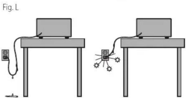
natural_image
Two identical diagrams of a laptop setup with connected cables and a small object, no text or symbols present.natural_image
Technical line drawing of an electronic component assembly (no text or symbols visible)4825 Highway 45 North
Jackson, Tennessee 38305
888-848-5175
www.portercable.com
Guide de dépannage
s'AssURER DE sUiVRE TOUTEs IEs DiRECTiVEs, Y COMPRis IEs COnsignEs DE sÉCURiTÉ
text_image
Technical diagram of a device with numbered components and labeled parts, including a POWER CABLE housing and mechanical assembly.natural_image
Technical diagram of a mechanical assembly with labeled components (no readable text or symbols)text_image
Technical diagram of a mechanical assembly with numbered components, likely a conveyor belt or pulley system.text_image
13 17 7 CBL CBL CBL CBL CBLtext_image
Technical diagram of a mechanical assembly with numbered components, likely for engineering or manufacturing documentation.Especificaciones
Voltaje 120 V
Amperios 6,5A
RPM 3600
natural_image
Line drawing of an electronic device mounted on a stand, showing internal components and mounting hardware (no text or symbols)Fig. L
natural_image
Two identical diagrams showing a laptop connected to a power cord and a small device, with no text or symbols present.Interruptor On/Off (Encendido/Apagado)
(Fig. L, M)
text_image
PORTER ORIBLEFig. Q
text_image
Technical diagram of an electronic device with Chinese annotations indicating component placement and mounting details.Eje Central Lázaro Cárdenas No. 18 - Local (55) 5588 9377 D, Col. Obrera
MERIDA, YUC
Calle 63 #459-A - Col. Centro (999) 928 5038
MONTERREY, N.L.
Av. Francisco I. Madero 831 Poniente - Col. (818) 375 23 13 Centro
PUEBLA, PUE
17 Norte #205 - Col. Centro (222) 246 3714
QUERETARO, QRO
Av. San Roque 274 - Col. San Gregorio (442) 2 17 63 14
SAN LUIS POTOSI, SLP
4825 Highway 45 North
Jackson, Tennessee 38305
(888) 848-5175
www.portercable.com
EsPECiFiCACiOnEs
PCE980 120 V Máx* 3600 rpm