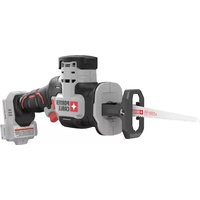
PCCM300 - Saw Porter-Cable - Free user manual and instructions
Find the device manual for free PCCM300 Porter-Cable in PDF.

| Product Type | Cordless Abrasive Cut-off Saw |
| Brand | Porter-Cable |
| Model | PCCM300 |
| Power Source | 20V Max Lithium-Ion Battery Pack |
| Wheel Diameter | 3 in (76 mm) |
| Arbor Size | 3/8 in (7/16 in adapter included) |
| Max Wheel Thickness | 0.09 in (2.2 mm) |
| Variable Speed | Yes, variable speed trigger |
| Rotation Direction | Forward / Reverse / Center Lock |
| Work Light | Integrated LED, activates with trigger |
| Rotating Guard | Yes, 3 tool-less adjustable positions |
| Shoe | Removable, depth adjustment knob |
| Dust Port Adapter | Yes, compatible with AirLock™ (sold separately) |
| Weight (estimated) | Approximately 1.4 kg |
| Dimensions (L × W × H) estimated | 28 × 10 × 20 cm |
| Warranty | 3-year limited |
| Recommended Cleaning | Dry compressed air, no solvents |
| Safety | Safety glasses (ANSI Z87.1), hearing protection, dust mask |
| Main Replacement Parts | Wheels, inner/outer flanges, arbor screw, shoe, guard, adapter |
| Repairability | Contact an authorized Porter-Cable service center |
Frequently Asked Questions - PCCM300 Porter-Cable
User questions about PCCM300 Porter-Cable
0 question about this device. Answer the ones you know or ask your own.
Ask a new question about this device
Download the instructions for your Saw in PDF format for free! Find your manual PCCM300 - Porter-Cable and take your electronic device back in hand. On this page are published all the documents necessary for the use of your device. PCCM300 by Porter-Cable.
USER MANUAL PCCM300 Porter-Cable
Thank you for choosing PORTER-CABLE! To register your new product, go to: www.portercable.com OPERATING INSTRUCTION, SERVICE CENTERS AND GUARANTEE POLICY.
⚠ WARNING: READ THIS INSTRUCTION BEFORE USING THE PRODUCT.
English (original instructions) 5
1 Battery pack
2 Battery pack release button
3 Main handle
4 Variable speed trigger
5 Forward/reverse/lock off button
6 Spindle lock button
7 Direction indicator
8 Dust port adapter
9 Shoe
10 Depth adjustment knob
11 Rotatable Guard
12 Hex wrench
13 LED worklight
14 Accessory attachment location
Fig. F1 Fig. F2
Indicators
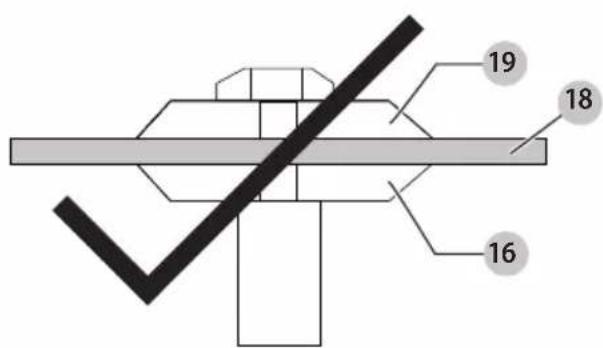
Fig. G Fig. H
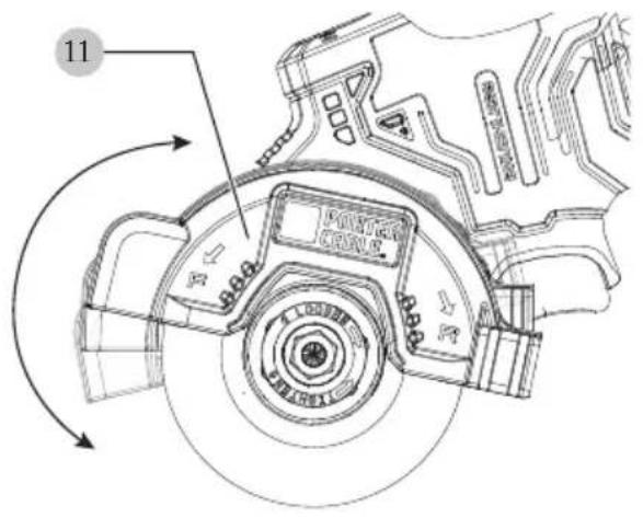
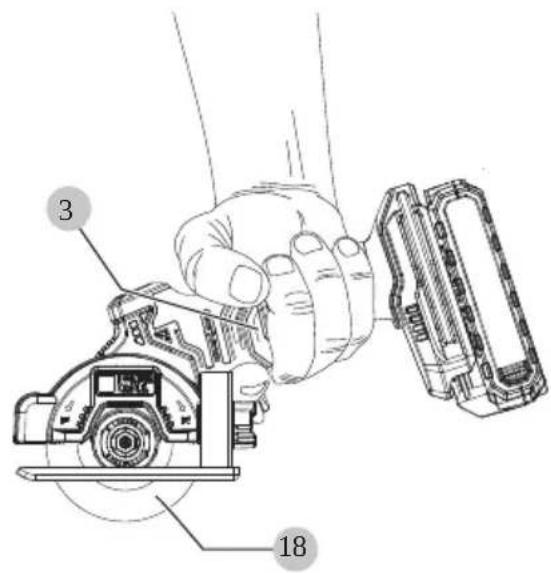
Fig.1
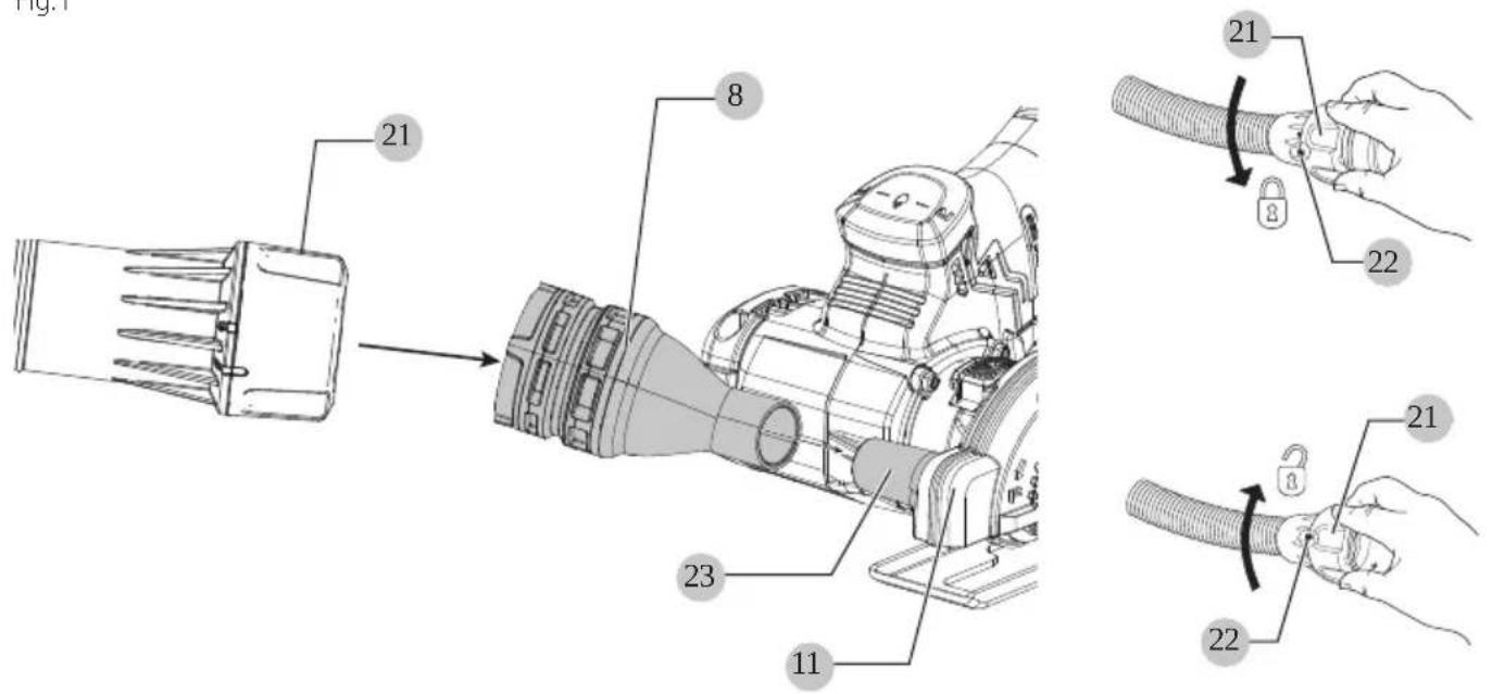
Fig. J1
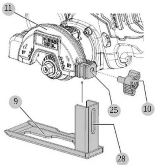
Fig. J2
WARNING: Read all safety warnings and all instructions. Failure to follow the warnings and instructions may result in electric shock, fire and/or serious injury.

WARNING: To reduce the risk of injury, read the instruction manual.
Intended Use
Your cut-off tool is designed for professional cutting applications.
DO nOT use in the presence of flammable liquids or gases.
Your cut-off tool is a professional power tool.
DO nOT let children come into contact with the tool.
Supervision is required when inexperienced operators use this tool.
Definitions: Safety Alert Symbols and Words
This instruction manual uses the following safety alert symbols and words to alert you to hazardous situations and your risk of personal injury or property damage.
DANGER: Indicates an imminently hazardous situation which, if not avoided, will result in death or serious injury.
WARNING: Indicates a potentially hazardous situation when, if not avoided, could result in death or serious injury.
CAUTION: Indicates a potentially hazardous situation which, if not avoided, may result in minor or moderate injury.
NOTICE: Indicates a practice not related to anal injury which, if not avoided, may result in property damage.
(Used without word) Indicates a safety related message.
GENERAL POWER TOOL SAFETY WARNINGS
WARNING: Read all safety warnings, instructions, indications and specifications provided with this power tool. Failure to follow all instructions listed below may result in electric shock, fire and/or serious injury.
SAVE All WARnIngs AnD InsTRUCTIONS FOR FUTURE REFEREnCE.
The term "power tool" in the warnings refers to your mains-operated (corded) power tool or battery-operated (cordless) power tool.
1) Work Area Safety
a) Keep work area clean and well lit. Cluttered or dark areas invite accidents.
b) Do not operate power tools in explosive atmospheres, such as in the presence of flammable liquids, gases or dust. Power tools create sparks which may ignite the dust or fumes.
c) Keep children and bystanders away while operating a power tool. Distractions can cause you to lose control.
2) Electrical Safety
a) Power tool plugs must match the outlet. Never modify the plug in any way. Do not use any adapter plugs with earthed (grounded) power tools. Unmodified plugs and matching outlets will reduce risk of electric shock.
b) Avoid body contact with earthed or grounded surfaces, such as pipes, radiators, ranges and refrigerators. There is an increased risk of electric shock if your body is earthed or grounded.
c) Do not expose power tools to rain or wet conditions. Water entering a power tool will increase the risk of electric shock.
d) Do not abuse the cord. Never use the cord for carrying, pulling or unplugging the power tool. Keep cord away from heat, oil, sharp edges or moving parts. Damaged or entangled cords increase the risk of electric shock.
e) When operating a power tool outdoors, use an extension cord suitable for outdoor use. Use of a cord suitable for outdoor use reduces the risk of electric shock.
f) If operating a power tool in a damp location is unavoidable, use a ground fault circuit interrupter (GFCI) protected supply. Use of a GFCI reduces the risk of electric shock.
3) Personal Safety
a) Stay alert, watch what you are doing and use common sense when operating a power tool. Do not use a power tool while you are tired or under the influence of drugs, alcohol or medication. A moment of inattention while operating power tools may result in serious personal injury.
b) Use personal protective equipment. Always wear eye protection. Protective equipment such as a dust mask, non-skid safety shoes, hard hat, or hearing protection used for appropriate conditions will reduce personal injuries.
c) Prevent unintentional starting. Ensure the switch is in the off position before connecting to power source and/or battery pack, picking up or carrying the tool. Carrying power tools with your finger on the switch or energizing power tools that have the switch on invites accidents.
d) Remove any adjusting key or wrench before turning the power tool on. A wrench or a key left attached to a rotating part of the power tool may result in personal injury.
e) Do not overreach. Keep proper footing and balance at all times. This enables better control of the power tool in unexpected situations.
f) Dress properly. Do not wear loose clothing or jewelry. Keep your hair, clothing and gloves away from moving parts. Loose clothes, jewelry or long hair can be caught in moving parts.
g) If devices are provided for the connection of dust extraction and collection facilities, ensure these are connected and properly used. Use of dust collection can reduce dust-related hazards.
English
h) Do not let familiarity gained from frequent use of tools allow you to become complacent and ignore tool safety principles. A careless action can cause severe injury within a fraction of a second.
4) Power Tool Use and Care
a) Do not force the power tool. Use the correct power tool for your application. The correct power tool will do the job better and safer at the rate for which it was designed.
b) Do not use the power tool if the switch does not turn it on and off. Any power tool that cannot be controlled with the switch is dangerous and must be repaired.
c) Disconnect the plug from the power source and/or remove the battery pack, if detachable, from the power tool before making any adjustments, changing accessories, or storing power tools. Such preventive safety measures reduce the risk of starting the power tool accidentally.
d) Store idle power tools out of the reach of children and do not allow persons unfamiliar with the power tool or these instructions to operate the power tool. Power tools are dangerous in the hands of untrained users.
e) Maintain power tools and accessories. Check for misalignment or binding of moving parts, breakage of parts and any other condition that may affect the power tool's operation. If damaged, have the power tool repaired before use. Many accidents are caused by poorly maintained power tools.
f) Keep cutting tools sharp and clean. Properly maintained cutting tools with sharp cutting edges are less likely to bind and are easier to control.
g) Use the power tool, accessories and tool bits, etc. in accordance with these instructions, taking into account the working conditions and the work to be performed. Use of the power tool for operations different from those intended could result in a hazardous situation.
h) Keep handles and grasping surfaces dry, clean and free from oil and grease. Slippery handles and grasping surfaces do not allow for safe handling and control of the tool in unexpected situations.
5) Battery Tool Use and Care
a) Recharge only with the charger specified by the manufacturer. A charger that is suitable for one type of battery pack may create a risk of fire when used with another battery pack.
b) Use power tools only with specifically designated battery packs. Use of any other battery packs may create a risk of injury and fire.
c) When battery pack is not in use, keep it away from other metal objects, like paper clips, coins, keys, nails, screws or other small metal objects, that can make a connection from one terminal to another. Shorting the battery terminals together may cause burns or a fire.
d) Under abusive conditions, liquid may be ejected from the battery; avoid contact. If contact accidentally occurs, flush with water. If liquid contacts eyes, additionally seek medical help. Liquid ejected from the battery may cause irritation or burns.
e) Do not use a battery pack or tool that is damaged or modified. Damaged or modified batteries may exhibit unpredictable behavior resulting in fire, explosion or risk of injury.
f) Do not expose a battery pack or tool to fire or excessive temperature. Exposure to fire or temperature above 265 °F (130 °C) may cause explosion.
g) Follow all charging instructions and do not charge the battery pack or tool outside the temperature range specified in the instructions.
Charging improperly or at temperatures outside the specified range may damage the battery and increase the risk of fire.
6) Service
a) Have your power tool serviced by a qualified repair person using only identical replacement parts. This will ensure that the safety of the power tool is maintained.
b) Never service damaged battery packs. Service of battery packs should only be performed by the manufacturer or authorized service providers.
CUT-OFF MACHINE SAFETY WARNINGS
a) The guard provided with the tool must be securely attached to the power tool and positioned for maximum safety, so the least amount of wheel is exposed towards the operator. Position yourself and bystanders away from the plane of the rotating wheel. The guard helps to protect operator from broken wheel fragments and accidental contact with wheel.
b) Use only bonded reinforced or diamond cut-off wheels for your power tool. Just because an accessory can be attached to your power tool, it does not assure safe operation.
c) The rated speed of the accessory must be at least equal to the maximum speed marked on the power tool. Accessories running faster than their rated speed can break and fly apart.
d) Wheels must be used only for recommended applications. For example: do not grind with the side of cut-off wheel. Abrasive cut-off wheels are intended for peripheral grinding, side forces applied to these wheels may cause them to shatter.
e) Always use undamaged wheel flanges that are of correct diameter for your selected wheel. Proper wheel flanges support the wheel thus reducing the possibility of wheel breakage.
f) Do not use worn down reinforced wheels from larger power tools. Wheels intended for a larger
power tool are not suitable for the higher speed of a smaller tool and may burst.
g) The outside diameter and the thickness of your accessory must be within the capacity rating of your power tool. Incorrectly sized accessories cannot be adequately guarded or controlled.
h) The arbour size of wheels and flanges must properly fit the spindle of the power tool. Wheels and flanges with arbour holes that do not match the mounting hardware of the power tool will run out of balance, vibrate excessively and may cause loss of control.
i) Do not use damaged wheels. Before each use, inspect the wheels for chips and cracks. If power tool or wheel is dropped, inspect for damage or install an undamaged wheel. After inspecting and installing the wheel, position yourself and bystanders away from the plane of the rotating wheel and run the power tool at maximum no load speed for one minute. Damaged wheels will normally break apart during this test time.
j) Wear personal protective equipment. Depending on application, use face shield, safety goggles or safety glasses. As appropriate, wear dust mask, hearing protectors, gloves and shop apron capable of stopping small abrasive or workpiece fragments. The eye protection must be capable of stopping flying debris generated by various operations. The dust mask or respirator must be capable of filtering particles generated by your operation. Prolonged exposure to high intensity noise may cause hearing loss.
k) Keep bystanders a safe distance away from work area. Anyone entering the work area must wear personal protective equipment. Fragments of workpiece or of a broken wheel may fly away and cause injury beyond immediate area of operation.
1) Hold the power tool by insulated gripping surfaces only, when performing an operation where the cutting accessory may contact hidden wiring. Cutting accessory contacting a "live" wire may make exposed metal parts of the power tool "live" and could give the operator an electric shock.
m) Never lay the power tool down until the accessory has come to a complete stop. The spinning wheel may grab the surface and pull the power tool out of your control.
n) Do not run the power tool while carrying it at your side. Accidental contact with the spinning accessory could snag your clothing, pulling the accessory into your body.
o) Regularly clean the power tool's air vents. The motor's fan will draw the dust inside the housing and excessive accumulation of powdered metal may cause electrical hazards.
p) Do not operate the power tool near flammable materials. Sparks could ignite these materials.
q) Do not use accessories that require liquid coolants. Using water or other liquid coolants may result in electrocution or shock.
FURTHER SAFETY INSTRUCTIONS FOR ABRASIVE CUTTING-OFF OPERATIONS
Kickback and Related Warnings
Kickback is a sudden reaction to a pinched or snagged rotating wheel, backing pad, brush or any other accessory. Pinching or snagging causes rapid stalling of the rotating accessory which in turn causes the uncontrolled power tool to be forced in the direction opposite of the accessory's rotation at the point of the binding.
For example, if an abrasive wheel is snagged or pinched by the workpiece, the edge of the wheel that is entering into the pinch point can dig into the surface of the material causing the wheel to climb out or kick out. The wheel may either jump toward or away from the operator, depending on direction of the wheel's movement at the point of pinching. Abrasive wheels may also break under these conditions.
Kickback is the result of power tool misuse and/or incorrect operating procedures or conditions and can be avoided by taking proper precautions as given below:
a) Maintain a firm grip on the power tool and position your body and arm to allow you to resist kickback forces. Always use auxiliary handle, if provided, for maximum control over kickback or torque reaction during start-up. The operator can control torque reaction or kickback forces, if proper precautions are taken.
b) Never place your hand near the rotating accessory. Accessory may kickback over your hand.
c) Do not position your body in line with the rotating wheel. Kickback will propel the tool in direction opposite to the wheel's movement at the point of snagging.
d) Use special care when working corners, sharp edges etc. Avoid bouncing and snagging the accessory. Corners, sharp edges or bouncing have a tendency to snag the rotating accessory and cause loss of control or kickback.
e) Do not attach a saw chain, woodcarving blade, segmented diamond wheel with a peripheral gap greater than 10 mm or toothed saw blade. Such blades create frequent kickback and loss of control.
f) Do not "jam" the wheel or apply excessive pressure. Do not attempt to make an excessive depth of cut. Overstressing the wheel increases the loading and susceptibility to twisting or binding of the wheel in the cut and the possibility of kickback or wheel breakage.
g) When wheel is binding or when interrupting a cut for any reason, switch off the power tool and hold the power tool motionless until the wheel comes to a complete stop. Never attempt to remove the wheel from the cut while the wheel is in motion otherwise kickback may occur. Investigate
English
and take corrective action to eliminate the cause of wheel binding.
h) Do not restart the cutting operation in the workpiece. Let the wheel reach full speed and carefully re-enter the cut. The wheel may bind, walk up or kickback if the power tool is restarted in the workpiece.
i) Support panels or any oversized workpiece to minimize the risk of wheel pinching and kickback. Large workpieces tend to sag under their own weight. Supports must be placed under the workpiece near the line of cut and near the edge of the workpiece on both sides of the wheel.
j) Use extra caution when making a "pocket cut" into existing walls or other blind areas. The protruding wheel may cut gas or water pipes, electrical wiring or objects that can cause kickback.
Additional Safety Warnings for Abrasive Cutting-Off Operations:
a) This power tool is intended to function as a cut-off tool. Read all safety warnings, instructions, illustrations and specifications provided with this power tool. Failure to follow all instructions listed below may result in electric shock, fire and/or serious injury.
b) Operations such as grinding, sanding, wire brushing, or polishing are not recommended to be performed with this power tool. Operations for which the power tool was not designed may create a hazard and cause personal injury Do not surface grind with side of wheel.
c) Do not use accessories which are not specifically designed and recommended by the tool manufacturer. Just because the accessory can be attached to your power tool, it does not assure safe operation.
d) The outside diameter and the thickness of your accessory must be within the capacity rating of your power tool. Incorrectly sized accessories cannot be adequately guarded or controlled.
e) The arbour size of wheels or flanges must properly fit the spindle of the power tool. Accessories with arbour holes that do not match the mounting hardware of the power tool will run out of balance, vibrate excessively and may cause loss of control.
f) When using segmented diamond wheels, use only diamond wheels with a peripheral gap not greater than 10 mm and negative rake angle.
g) Set the depth of cut for no more than necessary. The less wheel exposed, the less chance of binding and kickback. Before cutting, be sure adjust shoe assembly is tight.
h) Do not force the tool. Forcing a cut off tool reduces control and cutting efficiency.
i) If guard is not tight in position, do not use.
j) Do not use toothed blades. k) Do not use this tool as a table saw. l) Firmly secure the workpiece.
Additional Safety Information
WARNING: Never modify the power tool or any part of its damage or personal injury could result.
WARNING: ALWAYS use safety glasses. Everyday eyeglasses are NOT safety glasses. Also use face or dust mask if cutting operation is dusty. ALWAYS WEAR CERTIFIED SAFETY EQUIPMENT:
• ANSI Z87.1 eye protection (CAN/CSA Z94.3),
• ANSI S12.6 (S3.19) hearing protection,
• NIOSH/OSHA/MSHA respiratory protection.
WARNING: Some dust created by power sanding, sanding, grinding, drilling, and other construction activities contains chemicals known to the State of California to cause cancer, birth defects or other reproductive harm. Some examples of these chemicals are:
- lead from lead-based paints,
• crystalline silica from bricks and cement and other masonry products, and
• arsenic and chromium from chemically-treated lumber.
Your risk from these exposures varies, depending on how often you do this type of work. To reduce your exposure to these chemicals: work in a well ventilated area, and work with approved safety equipment, such as those dust masks that are specially designed to filter out microscopic particles.
WARNING: Use of this tool can generate and/or discharge dust, which may cause serious and permanent respiratory or other injury. Always use NIOSH/OSHA approved respiratory protection appropriate for the dust exposure. Direct particles away from face and body.
WARNING: Always wear proper personal hearing production that conforms to ANSI S12.6 (S3.19) during use. Under some conditions and duration of use, noise from this product may contribute to hearing loss.
- Wear protective clothing and wash exposed areas with soap and water. Allowing dust to get into your mouth, eyes, or lay on the skin may promote absorption of harmful chemicals. Direct particles away from face and body.
- Use the appropriate dust extractor vacuum to remove the vast majority of static and airborne dust. Failure to remove static and airborne dust could contaminate the working environment or pose an increased health risk to the operator and those in close proximity.
- Use clamps or other practical ways to secure and support the workpiece to a stable platform. Holding the work by hand or against your body is unstable and may lead to loss of control and injury.
• Air vents often cover moving parts and should be avoided. Loose clothes, jewelry or long hair can be caught in moving parts.
CAUTION: When not in use, place tool on its side on a stable surface where it will not cause a tripping or falling hazard. Some tools with large battery packs will stand upright on the battery pack but may be easily knocked over.
The label on your tool may include the following symbols. The symbols and their definitions are as follows:
V....volts
Hz hertz
min......minutes
- - - or DC .....direct current
Class I Construction (grounded)
.../min.....per minute
BPM.....beats per minute
or AC/DC....alternating or direct current
Class II Construction (double insulated)
n_0 .....no load speed n .....rated speed
PSI..... pounds per square inch
± ......earthing terminal
⚠️ ......safety alert symbol
▲......visible radiation—do not stare into the light
E....wearrespiratory protection
wear eye protection
○....wearhearing protection
read all documentation
do not expose to rain
BATTERIES AND CHARGERS
The battery pack is not fully charged out of the carton. Before using the battery pack and charger, read the safety instructions below and then follow charging procedures outlined. When ordering replacement battery packs, be sure to include the catalog number and voltage.
READ ALL INSTRUCTIONS
Important Safety Instructions for All Battery Packs
WARNING: Read all safety warnings, instructions, and cautionary markings for the battery pack, charger and product. Failure to follow the warnings and instructions may result in electric shock, fire and/or serious injury.
- Do not charge or use the battery pack in explosive atmospheres, such as in the presence of flammable liquids, gases or dust. Inserting or removing the battery pack from the charger may ignite the dust or fumes.
- NEVER force the battery pack into the charger. DO NOT modify the battery pack in any way to fit into a non-compatible charger as battery pack may rupture, causing serious personal injury. Consult the chart at the end of this manual for compatibility of batteries and chargers.
- Charge the battery packs only in PORTER-CABLE chargers.
• DO NOT splash or immerse in water or other liquids.
• DO NOT allow water or any liquid to enter battery pack.
- Do not store or use the tool and battery pack in locations where the temperature may reach or exceed 104 °F (40 °C) (such as outside sheds or metal buildings in summer). For best life, store battery packs in a cool, dry location.
NOTE: Do not store the battery packs in a tool with the trigger switch locked on. Never tape the trigger switch in the ON position.
- Do not incinerate the battery pack even if it is severely damaged or is completely worn out. The battery pack can explode in a fire. Toxic fumes and materials are created when lithium-ion battery packs are burned.
- Do not expose a battery pack or appliance to fire or excessive temperature. Exposure to fire or temperature above 265 °F (130 °C) may cause explosion.
- Follow all charging instructions and do not charge the battery pack or appliance outside of the temperature range specified in the instructions. Charging improperly or at temperatures outside of the specified range may damage the battery and increase the risk of fire.
- If battery contents come into contact with the skin, immediately wash area with mild soap and water. If battery liquid gets into the eye, rinse water over the open eye for 15 minutes or until irritation ceases. If medical attention is needed, the battery electrolyte is composed of a mixture of liquid organic carbonates and lithium salts.
- Contents of opened battery cells may cause respiratory irritation. Provide fresh air. If symptoms persist, seek medical attention.
- Battery liquid may be flammable if exposed to spark or flame.
- Never attempt to open the battery pack for any reason. If the battery pack case is cracked or damaged, do not insert into the charger. Do not crush, drop or damage the battery pack. Do not use a battery pack or charger that has received a sharp blow, been dropped, run over or damaged in any way (e.g., pierced with a nail, hit with a hammer, stepped on). Damaged battery packs should be returned to the service center for recycling.
Storage Recommendations
The best storage place is one that is cool and dry, away from direct sunlight and excess heat or cold. Store the fully charged battery pack out of the charger.
Battery Pack Cleaning Instructions
Dirt and grease may be removed from the exterior of the battery pack using a cloth or soft non-metallic brush. Do not use water or any cleaning solutions.
Fuel Gauge Battery Packs (Fig. B)
Some battery packs include a fuel gauge. When the fuel gauge button is pressed and held, the LED lights will indicate the approximate level of charge remaining. This does not indicate tool functionality and is subject to variation based on product components, temperature, and end-user application.
Transportation

WARNING: Fire hazard. Do not store, carry, or transport the battery pack so that metal objects can contact exposed battery terminals. For example, do not place the battery pack in aprons, pockets, tool boxes, product kit boxes, drawers, etc., with loose nails, screws, keys, coins, hand tools, etc. When transporting individual battery packs, make sure that the battery terminals are protected and well insulated from materials that could contact them and cause a short circuit. NOTE: Li-ion battery packs should not be put in checked baggage on airplanes and must be properly protected from short circuits if they are in carry-on baggage.
The RBRC® Seal
Please take your spent battery packs to an authorized PORTER-CABLE service center or to your local retailer for recycling. In some areas, it is illegal to place spent battery packs in the trash. You may also contact your local recycling center for information on where to drop off the spent battery pack. Do not place in curbside recycling. For more information visit www.call2recycle.org or call the toll-free number in the RBRC® Seal.
RBRC ^® is a registered trademark of Call 2 Recycle, Inc.

Important Safety Instructions for All Battery Chargers

WARNING: Read all safety warnings, instructions, and cautionary markings for the battery pack, charger and product. Failure to follow the warnings and instructions may result in electric shock, fire and/or serious injury.
- DO NOT attempt to charge the battery pack with any chargers other than a PORTER-CABLE charger. PORTER-CABLE chargers and battery packs are specifically designed to work together.
• These chargers are not intended for any uses other than charging PORTER-CABLE rechargeable battery packs. Charging other types of battery packs may cause them to overheat and burst, resulting in personal injury, property damage, fire, electric shock or electrocution.
- Do not expose the charger to rain or snow.
- Do not allow water or any liquid to enter charger.
- Pull by the plug rather than the cord when disconnecting the charger. This will reduce the risk of damage to the electric plug and cord.
- Make sure that the cord is located so that it will not be stepped on, tripped over or otherwise subjected to damage or stress.
- Do not use an extension cord unless it is absolutely necessary. Use of improper extension cord could result in risk of fire, electric shock or electrocution.
- When operating a charger outdoors, always provide a dry location and use an extension cord suitable for outdoor use. Use of a cord suitable for outdoor use reduces the risk of electric shock.
- An extension cord must have adequate wire size (AWG or American Wire Gauge) for safety. The smaller the gauge number of the wire, the heavier the cord and thus the greater its capacity. An undersized cord will cause a drop in line voltage, resulting in loss of power and overheating. The following table shows the correct size to use depending on total length of all extension cords plugged together, and nameplate ampere rating. If in doubt, use the next heavier gauge.
Minimum Gauge for Cord Sets
| Volts | Total Length of Cord in Feet (meters) | ||||
| 120V 25 (7.6) 50 (15.2) 100 (30.5) 150 (45.7) | |||||
| Ampere Rating | American Wire Gauge | ||||
| More Than Not More Than | |||||
| 0 6 18 16 16 14 | |||||
| 6 10 18 16 14 12 | |||||
| 10 12 16 16 14 12 | |||||
| 12 16 14 12 Not Recommended | |||||
- Do not place any object on top of the charger or place the charger on a soft surface that might block the ventilation slots and result in excessive internal heat. Place the charger in a position away from any heat source. The charger is ventilated through slots in the top and the bottom of the housing.
- Do not operate the charger with a damaged cord or plug. Have them replaced immediately.
- Do not operate the charger if it has received a sharp blow, been dropped or otherwise damaged in any way. Take it to an authorized service center.
- Do not disassemble the charger; take it to an authorized service center when service or repair is required. Incorrect reassembly may result in a risk of electric shock, electrocution or fire.
- The charger is designed to operate on standard 120V household electrical power. Do not attempt to use it on any other voltage. This does not apply to the vehicular charger.
- Foreign materials of a conductive nature, such as, but not limited to, grinding dust, metal chips, steel wool, aluminum foil or any buildup of metallic particles should be kept away from the charger cavities and ventilation slots.
• Always unplug the charger from the power supply when there is no battery pack in the cavity.
Charging a Battery (Fig. A, C)
PORTER-CABLE chargers are designed to charge PORTER-CABLE battery packs. Charge times are: PCC690L in 40–80 mins., PCC691L in 70–140 mins., PCC692/PCC692L in 40–80 mins., and PCC695L/PCC699L in 180-360 mins. depending on the pack being charged.
- Plug the charger into an appropriate outlet.
- Insert and fully seat battery pack 1. The red charging light(s) will continuously blink while charging.
- Charging is complete when the red charging light(s) remain(s) continuously ON. Battery pack can be left in charger or removed.
WARNING: Only charge batteries in air temperature over 40°C (4.5°C) and below 104°F (40°C).
- Charger will not charge a faulty battery pack, which may be indicated by the charging light(s) staying OFF. Take charger and battery pack to an authorized service center if light(s) stay(s) OFF.
NOTE: Refer to label near charging light(s) on charger for blink patterns.
NOTE: To remove the battery pack, some chargers require the battery pack release button 2 to be pressed.
Hot/Cold Pack Delay
When the charger detects a battery pack that is too hot or too cold, it automatically starts a Hot/Cold Pack Delay, suspending charging until the battery pack has reached an appropriate temperature. The charger then automatically switches to the pack charging mode. This feature ensures maximum battery pack life.
A cold battery pack may charge at a slower rate than a warm battery pack.
The hot/cold pack delay will be indicated by the red light(s) continuing to blink but with the yellow light continuously ON. Once the battery pack has reached an appropriate temperature, the yellow light will turn OFF and the charger will resume the charging procedure.
Electronic Protection System
Li-ion tools are designed with an Electronic Protection System that will protect the battery pack against overloading, overheating or deep discharge. The tool will automatically turn off and the battery pack will need to be recharged.
Important Charging Notes
- Longest life and best performance can be obtained if the battery pack is charged when the air temperature is between 65^ F – 75^ F ( 18^ C – 24^ C). DO NOT charge when the battery pack is below 40^ F ( 4.5^ C), or above 104^ F ( 40^ C). This is important and will prevent serious damage to the battery pack.
- The charger and battery pack may become warm to the touch while charging. This is a normal condition, and does not indicate a problem. To facilitate the cooling of the battery pack after use, avoid placing the charger or battery pack in a warm environment such as in a metal shed or an uninsulated trailer.
- If the battery pack does not charge properly:
a. Check operation of receptacle by plugging in a lamp or other appliance;
b. Check to see if receptacle is connected to a light switch which turns power off when you turn out the lights;
c. If charging problems persist, take the tool, battery pack and charger to your local service center.
- You may charge a partially used pack whenever you desire with no adverse effect on the battery pack.
Charger Cleaning Instructions
WARNING: Shock hazard. Disconnect the charger from the AC outlet before cleaning. Dirt and grease may be removed from the exterior of the charger using a cloth or soft non-metallic brush. Do not use water or any cleaning solutions.
SAVE THESE INSTRUCTIONS FOR FUTURE USE
Wall Mounting
Some PORTER-CABLE chargers are designed to be wall mountable or to sit upright on a table or work surface. If wall mounting, locate the charger within reach of an electrical outlet, and away from a corner or other obstructions which may impede air flow. Use the back of the charger as a template for the location of the mounting screws on the wall. Mount the charger securely using drywall screws (purchased separately) at least 1" (25.4 mm) long, with a screw head diameter of 0.28–0.35" (7–9 mm), screwed into wood to an optimal depth leaving approximately 7/32" (5.5 mm) of the screw exposed. Align the slots on the back of the charger with the exposed screws and fully engage them in the slots.
ASSEMBLY AND ADJUSTMENTS
WARNING: To reduce the risk of serious personal injury, turn unit off and remove the battery pack before making any adjustments or removing/installing attachments or accessories. An accidental start-up can cause injury.
WARNING: Wheels, cutting material and metal components on the tool such as gearcase, shoe and guard may be hot during or after continued use. Use caution when approaching these areas.
Wheels
WARNING: To reduce the risk of injury, only use wheels that are no greater than 3" (76 mm) in diameter, have an inner diameter of 3/8" (or 7/16" if using adapter ring), and without cutting teeth. Thickness of wheel not to exceed 0.09" (2.2 mm). Never force a wheel onto the machine or alter the size of the arbor hole.
A dull wheel will cause slow inefficient cutting, overload the motor, could cause excessive splintering, and could increase the possibility of kickback. Please refer to the table below to determine the correct wheel for your application.
Wheel type Application
| Diamond** Multi-Material Wheel | Drywall, fiber cement, plastic, steel, non ferrous materials |
| Bonded Reinforced Wheel | Steel, stainless steel, non-ferrous materials |
| Diamond** Tile Wheel | Ceramic Tile, Porcelain and Granite/Marble/Stone |
**This blade uses manufactured diamonds engineered for cutting.
NOTE: Bonded Reinforced wheels are composed of abrasive grains which are held tightly together by a bonding agent and typically reinforced with a woven material.
Installing/Replacing Wheels
(Fig. A, E, F1, F2, L)
WARNING: Burn Hazard. Sharp parts. ALWAYS wear glaces when changing wheels. Wheels have sharp edges or may get extremely hot during operation, and may damage bare hands.
WARNING: To reduce the risk of injury, only use wheels that are no greater than 3" (76 mm) in diameter, have an inner diameter of 3/8" (or 7/16" if using adapter ring), and without cutting teeth. Thickness of wheel not to exceed 0.09" (2.2 mm). Never force a wheel onto the machine or alter the size of the arbor hole.
WARNING: Since accessories, other than those ordered by PORTER-CABLE, have not been tested with this product, use of such accessories with this tool could be hazardous. To reduce the risk of injury, only PORTER-CABLE recommended accessories should be used with this product.
WARNING: Failure to properly seat the flanges and/or a wheel could result in serious injury (or damage to the tool or wheel).
- Remove the battery.
- Lay unit on a firm surface, with the spindle 15 facing upward.
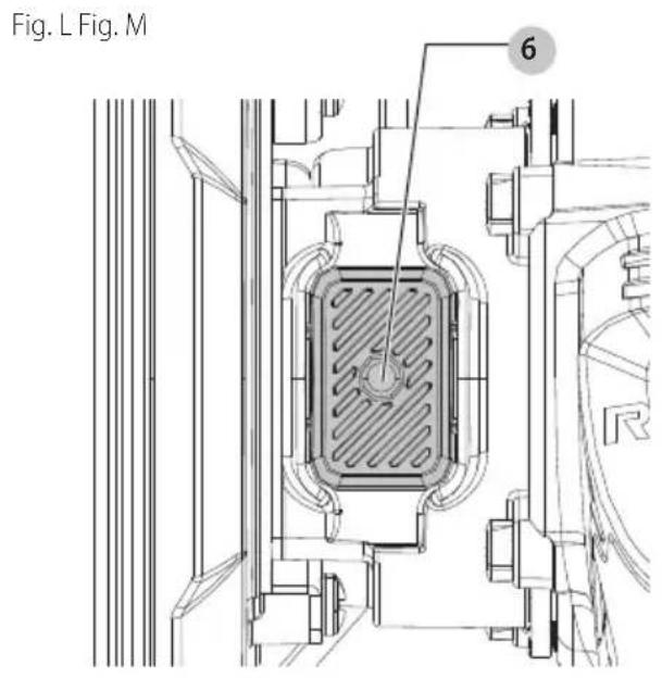
- Hold spindle lock button 6 to keep the spindle from turning. Spindle threads are left hand.
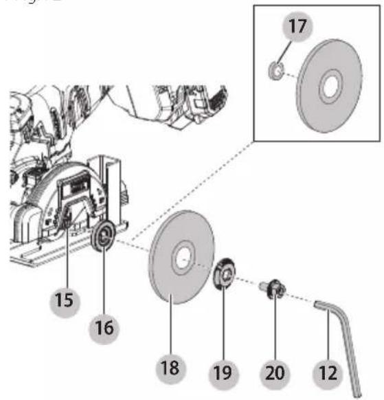
- Using supplied 6 mm hex wrench 12, rotate clockwise to remove spindle screw 20, outer flange 19, and used wheel 18 if one is installed. Leave inner flange 16 in place.
nOTE: Hex wrench is magnetically secured.
NOTE: It is possible that the inner flange and outer flange may stick together. Be sure to keep both flanges separated during the wheel installation process. Refer to Fig. F2 showing the correct order of the flanges and wheel installed over the spindle.
- Ensure inner flange is installed over the spindle.
NOTE: Your tool comes provided with a 7/16" arbor adapter 17 which should only be used when installing a 7/16" wheel. The 7/16" arbor adapter is not to be used with the wheels provided with this tool. When installing 7/16" wheels, place the 7/16" arbor adaptor over the inner flange. The 7/16" arbor adapter will fit inside the center of the 7/16" wheel when assembled. Refer to Fig. F1.
- Slip wheel over spindle. Make sure wheel goes over pilot diameter of inner flange.
NOTE: When installing diamond wheels, always match direction of rotation of the wheel to the desired direction of rotation of the tool.
- Slip on outer flange with the flat side towards the wheel.
nOTE: The text "LOOSEN TIGHTEN" will be visible when installed correctly.
- Start threading on spindle screw counterclockwise which will self align outer flange. Make sure the wheel is fitted in the correct orientation.
- Depress and hold spindle lock button and tighten spindle screw with hex wrench. Do not overtighten spindle screw.
- Release spindle lock button and turn wheel by hand to ensure it is properly centered. The wheel should not hit the shoe, guard or spindle screw. The spindle screw and flanges should be tight.
nOTE: Do not run tool with the spindle lock engaged.
Always allow motor to come to a complete stop before engaging the spindle lock.
Adjusting the Rotatable Guard Angle (Fig. G)
WARNING: Remove battery first. To reduce the risk of injury, ALWAYS adjust the guard to provide the best control and protection. ALWAYS wear gloves to protect your hands when adjusting the guard as the guard may get hot.
WARNING: Adjust the position of the guard to provide the maximum protection from loose particles and sparks thrown from the wheel.
CAUTION: Guard must be used with all cutting wheels.
- Remove the battery.
- Grasp the rotatable guard 11 firmly and rotate until it snaps securely into one of three positions.
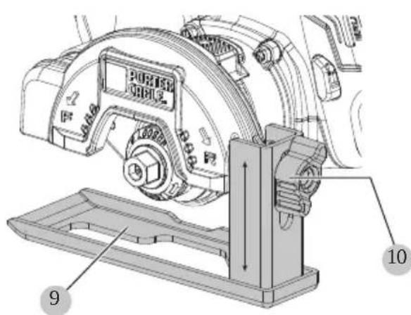
Mounting, Removing the Shoe (Fig. A, J1)
Your cut off tool comes pre-assembled with the shoe 9 mounted to the rotatable guard 11.
To Remove the Shoe
- Remove the battery pack 1.
- Loosen the depth adjustment knob 10 counterclockwise.
- Remove the depth adjustment knob and remove shoe from the rotatable guard.
To Mount the Shoe
- Remove the battery pack.
- Install shoe onto the back of the rotatable guard, aligning slot 28 to threaded hole 25 on guard. Refer to Fig. J1.
- Install and rotate the depth adjustment knob clockwise to tighten.
NOTE: The shoe is not required for use with this tool. For best performance the shoe is recommended for more stability when cutting on a flat surface.
Adjusting the Depth of Cut (Fig. J2)
- Loosen the depth adjustment knob 10 and slide the shoe 9 up or down. Adjust the cutting depth to the thickness of the workpiece. Less than 1/4" of the wheel should be visible below the workpiece.
- After depth of cut is selected tighten the depth adjustment knob
LED Worklight (Fig. A)
The LED worklight 13 will activate when the variable speed trigger 4 is depressed, and will automatically turn off 20 seconds after the variable speed trigger is released. If the variable trigger switch remains depressed, the LED worklight will remain on.
nOTE: The LED worklight is for lighting the immediate work surface and is not intended to be used as a flashlight.
Attaching the Dust Port Adaptor (Fig. A, I)
A dust port adaptor 8 comes available for use with this tool. This accessory connects directly to the tool's rotatable guard 11.
- Remove the battery pack 1.
- Friction fit the dust port adaptor 8 onto the dust port hole 23 located near the front tip of the rotatable guard.
Attaching an AirLock™ Compatible Dust Extractor (Fig. A, I)
(Sold Separately)
WARNING: Do not use dust extraction when cutting metal. Swarf from metal cutting may be hot and may spark which can melt vacuum hoses and may cause a fire inside the vacuum.
WARNING: When using dust extraction, empty v#m before work begins and often during work. Use care in disposing of dust. Materials in fine dust can be explosive.
The dust port adaptor 8 allows you to connect the tool to an external dust extractor using a AirLock™ connection system (sold separately), or a standard 32 mm dust extractor fitment. The AirLock™ allows for a fast, secure connection between the AirLock™ connector 21 and your tool's dust port adaptor.
- Remove the battery pack 1.
- Ensure the collar on the AirLock™ connector is in the unlock position. (Refer to Figure I.) Align notches 22 on collar and AirLock™ connector as shown for unlock and lock positions.
- Push the AirLock™ connector onto the connection point of the dust port adaptor. (Refer to Fig. I)
- Rotate the collar to the locked position. nOTE: The ball bearings inside collar lock into slot and secure the connection. The power tool is now securely connected to the dust extractor.
OPERATION
WARNING: To reduce the risk of serious personal injury, turn unit off and remove the battery pack before making any adjustments or removing/installing attachments or accessories. An accidental start-up can cause injury.
Installing and Removing the Battery Pack (Fig. D)
WARNING: Ensure the tool/appliance is in the off position before inserting the battery pack.
nOTE: For best results, make sure your battery pack is fully charged.
- To install the battery pack 1 into the tool handle, align the battery pack with the rails inside the tool's handle and slide it into the handle until the battery pack is firmly seated in the tool and ensure that it does not disengage.
- To remove the battery pack from the tool, press the battery pack release button 2 and firmly pull the battery pack out of the tool handle. Insert it into the charger as described in the charger section of this manual.
Proper Hand Position (Fig. H)
WARNING: To reduce the risk of serious personal injury, ALWAYS use proper hand position as shown. WARNING: To reduce the risk of serious personal injury, ALWAYS hold securely in anticipation of a sudden reaction. WARNING: Keep your free hand far from closing action. Do not reach underneath the workpiece.
Proper hand position requires one hand on the main handle 3.
Variable Speed Trigger (Fig. A)
The tool is turned on and off by pulling and releasing the variable speed trigger 4. The variable speed trigger permits speed control—the farther the trigger is depressed, the higher the speed of the tool.
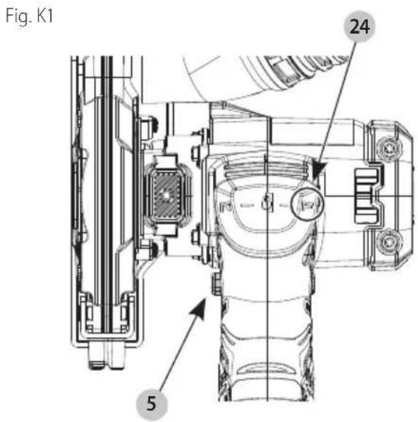
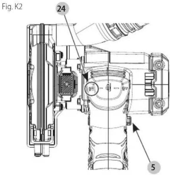
Forward/Reverse/Lock Off Button
(Fig. A, K1–K2)
CAUTION: Before changing the position of the control button, be sure the trigger is released.
Your cut-off tool is equipped with a forward/reverse/lock off button 5. There is a wheel indicator label 24 located above the main handle 3 that will help to identify the current direction mode of the tool. Some applications or accessories may require the tool to be run in forward or reverse. When making a cut, select the direction of cut that allows the tool to be pushed away from your body. Always operate tool in correct rotation for wheel selected.
- Forward (counterclockwise rotation) — Located on the right side of the tool near the variable speed trigger 4, push the forward/reverse/lock off button 5 to the far left. Refer to Fig. K1. The forward direction of the wheel is also noted by the direction indicator 7 located on the rotatable guard 11. Refer to Fig. A.
- Reverse (clockwise rotation) — Located on the left side of the tool near the variable speed trigger 4, push the forward/reverse/lock off button 5 to the far right. Refer to Fig. K2. The reverse direction of the wheel is also noted by the direction indicator 7 located on the rotatable guard 11. Refer to Fig. A.
ENGLISH
- The center position of the forward/reverse/lock off button locks the tool in the off position. When locked the variable speed trigger cannot be depressed.
NOTE: Keep the button in the center locked position when the tool is not in use or when being transported.
To Operate (Fig. A, H)
CAUTION: Before attempting to start, grasp too firmly.
WARNING: To reduce the risk of injury, DO NOT use a toothed blade.
WARNING: This tool is intended to be used dry. Whether cooling is necessary, use a spray bottle with clean water to lightly wet surface only, avoid over-wetting the workpiece. NEVER immerse your tool or battery pack in any liquid or allow liquid inside them.
WARNING: Wheels used for cutting may break or kick back if they bend or twist while the tool is being used to do cut-off work.
WARNING: Do not bang or bump a cut-off wheel when starting or during a cut.
- Grasp main handle 3 firmly.
- Line up wheel 18 with material to be cut. Be sure nothing is near or in line with the wheel.
- Depress and hold the variable speed trigger 4. Slowly feed the wheel into the workpiece with firm even pressure, allowing the tool to do the work. Do not force the cut off tool through the workpiece. Forcing a cut off tool can cause kickback. For maximum efficiency and wheel life, keep the wheel speed high.
- While cutting, if using the shoe, keep the shoe against the workpiece and maintain a firm grip.
NOTE: If making a partial cut, restarting a cut, or correcting cut direction, allow the wheels to come to a complete stop. To resume cutting, pull the variable speed trigger and re-enter the cut slowly.
- To stop tool, release the variable speed trigger.
General Tips for Cutting Materials
- For best control, user cutting direction should be opposite wheel rotation. Example: When making a cut away from user by pushing the tool forward, set wheel rotation to reverse/clockwise direction.
- Be sure that the wheel is at full speed before continuing a cut.
- Allow the wheel to come to a complete stop before raising the wheel out of the material.
Cutting Tile
- To reduce overheating of cutting wheel or workpiece, user may lightly wet surface.
- If excessive chipping of the tile is observed, user may operate tool at slower speed using variable speed trigger to achieve a cleaner cut.
- Cutting tile will generate debris. Guard position may be adjusted to deflect debris away from user.
Cutting Plastic
- Take frequent breaks to allow wheel to cool down.
- If melted material or debris becomes adhered to blade, shoe or guard: Release trigger. Allow unit to rest and material to cool. Remove battery. Remove debris. Ensure all areas around wheel including inside of guard is clear of debris. Resume cutting operation.
Cutting Metals
Observe the following to avoid potential hazards when cutting metals.
- During and shortly after cutting operation the material, wheel and metal components on the tool such as gearcase, guard and shoe may get hot.
- Allow these areas to cool before touching to avoid injury.
- Cutting metal will generate sparks. Guard position may be adjusted to deflect sparks and debris away from user.
- Cutting material and cutting wheel may have sharp or jagged edges after cutting operation. Wear gloves and use caution when touching these areas.
Transportation and Storage
During transportation and storage lock the variable speed trigger with the lock-off button. Refer to the Forward/Reverse/Lock Off Button section.
Remove the battery pack during the tool storage.
MAINTENANCE
WARNING: To reduce the risk of serious personal injury, turn unit off and remove the battery pack before making any adjustments or removing/installing attachments or accessories. An accidental start-up can cause injury.
Your PORTER-CABLE power tool has been designed to operate over a long period of time with a minimum of maintenance. Continuous satisfactory operation depends upon proper tool care and regular cleaning.
Accessories
WARNING: Since accessories, other than those carried by PORTER-CABLE, have not been tested with this product, use of such accessories with this product could be hazardous. To reduce the risk of injury, only PORTER-CABLE recommended accessories should be used with this product.
WARNING: Handle and store all abrasive wheels generally to prevent damage from thermal shock, heat, mechanical damage, etc. Store in a dry protected area free from high humidity, freezing temperatures or extreme temperature changes.
Recommended accessories for use with your product are available at extra cost from your local dealer or authorized service center. If you need assistance in locating any accessory, please contact PORTER-CABLE Call 1-888-848-5175 or visit our website:
www.portercable.com.
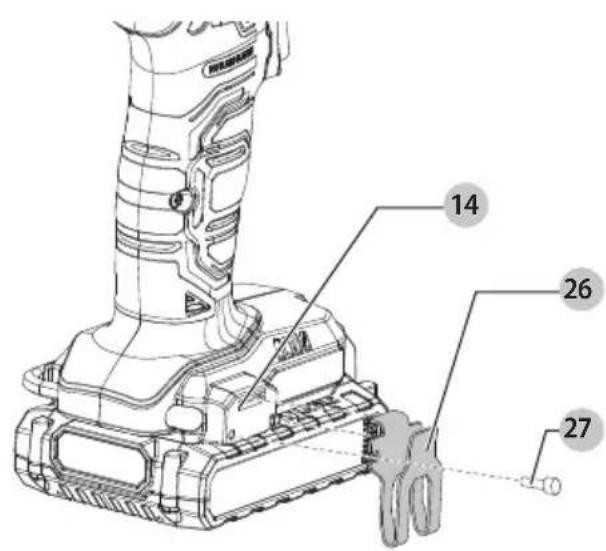
Belt Hook (Fig. M)
Optional accessory, sold separately.
WARNING: To reduce the risk of serious personal injury, turn tool off and disconnect battery pack before making any adjustments or removing/installing attachments or accessories.
WARNING: To reduce the risk of serious personal injury, DO NOT suspend tool overhead or suspend objects from the belt hook. ONLY hang tool's belt hook from a work belt.
WARNING: To reduce the risk of serious personal injury, ensure the screw holding the belt hook is secure.
CAUTION: To reduce the risk of personal injury or damage, DO NOT use the belt hook to hang the tool.
IMPORTANT: When attaching or replacing the belt hook 26, use only the screw 27 that is provided. Be sure to securely tighten screw.
If the belt hook is not desired at all, it can be removed from the tool.
- Place the belt hook onto the accessory attachment location 14 at the base of the tool.
- Use a screwdriver to secure the belt hook with the provided screw. Do not use any other screw for this.
To remove the belt hook, remove the screw that holds the belt hook in place.
Cleaning
WARNING: Blow dirt and dust out of all air vents with dry air at least once a week. To minimize the risk of eye injury, always wear ANSI Z87.1 approved eye protection when performing this procedure.
WARNING: Never use solvents or other harsh chemicals for cleaning the non-metallic parts of the tool. These chemicals may weaken the plastic materials used in these parts. Use a cloth dampened only with water and mild soap. Never let any liquid get inside the tool; never immerse any part of the tool into a liquid.
Repairs
The charger and batteries are not serviceable. There are no serviceable parts inside the charger or battery pack.
WARNING: To assure product SAFETY and RECEPTIBILITY, repairs, maintenance and adjustment (including brush inspection and replacement, when applicable) should be performed by a factory service center or an authorized service center. Always use identical replacement parts.
Register Online
Thank you for your purchase. Register your product now for:
- WARRANTY SERVICE: Registering your product will help you obtain more efficient warranty service in case there is a problem with your product.
- CONFIRMATION OF OWNERSHIP: In case of an insurance loss, such as fire, flood or theft, your
registration of ownership will serve as your proof of purchase.
• FOR YOUR SAFETY: Registering your product will allow us to contact you in the unlikely event a safety notification is required under the Federal Consumer Safety Act.
- Register online at.
Three-Year Limited Warranty
For warranty terms, go to https://www.portercable.com/service-support/warranty-information.
To request a written copy of the warranty terms, contact: Customer Service at PORTER-CABLE, 4825 Highway 45 North, Jackson, Tennessee 38305 or call 1-888-848-5175.
LATIN AMERICA: This warranty does not apply to products sold in Latin America. For products sold in Latin America, see country-specific warranty information contained in the packaging, call the local company, or see website for warranty information.
FREE WARNING LABEL REPLACEMENT: If your warning labels become illegible or are missing, call 1-888-848-5175 for a free replacement.
PORTER-CABLE
4825 Highway 45 North, Jackson, Tennessee 38305
1-888-848-5175 • www.portercable.com
4825 Highway 45 North, Jackson, Tennessee 38305
1-888-848-5175 • www.portercable.com
Eje Central Lázaro Cárdenas No. 18 - Local (55) 5588 9377 D, Col. Obrera
MERIDA, YUC
Calle 63 #459-A - Col. Centro (999) 928 5038
MONTERREY, N.L.
Av. Francisco I. Madero 831 Poniente - Col. (818) 375 23 13 Centro
PUEBLA, PUE
17 Norte #205 - Col. Centro (222) 246 3714
QUERETARO, QRO
Av. San Roque 274 - Col. San Gregorio (442) 2 17 63 14
SAN LUIS POTOSI, SLP
Col. Santa Fe Alvaro Obregon,
Ciudad de Mexico, Mexico.
C.P 01210
TEL(52) 55 53267100
R.F.C.BDE8106261W7
Registro en Línea
4825 Highway 45 North, Jackson, Tennessee 38305
1-888-848-5175 · www.portercable.com
PORTER-CABLE BATTERY AND CHARGER SYSTEMS
JING: Use of any other battery packs may create a risk of injury and fire.