OSC 18 - Multitools FESTOOL - Free user manual and instructions
Find the device manual for free OSC 18 FESTOOL in PDF.

| Product type | Cordless oscillating multi-tool |
| Brand | Festool |
| Model | OSC 18 |
| Motor voltage | 18 V |
| Speed (rpm) | 10,000 - 19,500 rpm |
| Oscillation angle | 2 x 2.0° |
| Tool holder | Starlock (compatible StarlockMax/Plus) |
| Weight (according to EPTA) | 1.6 kg |
| Power supply | Festool BP 18 series battery |
| Intended use | Sawing wood, plastic, metal (max 1 mm), tile joints, mastic, carpet |
| Sound pressure level | 83 dB(A) |
| Sound power level | 93 dB(A) |
| Speed regulation | Continuous via thumbwheel |
| Tool change | Tool-free (clamping lever) |
| Battery capacity display | 3-LED charge indicator |
| Protection | Automatic shut-off in case of blockage or overheating |
| Dust extraction device | Accessory available (mounts on adapter) |
| Depth stop | With parallel guide (accessory) |
| Positioning aid | Accessory for precise cuts |
| Maintenance | Clean ventilation slots with dry compressed air |
| Repairability | Festool authorized service only |
| Spare parts | Festool original parts only |
Frequently Asked Questions - OSC 18 FESTOOL
User questions about OSC 18 FESTOOL
0 question about this device. Answer the ones you know or ask your own.
Ask a new question about this device
Download the instructions for your Multitools in PDF format for free! Find your manual OSC 18 - FESTOOL and take your electronic device back in hand. On this page are published all the documents necessary for the use of your device. OSC 18 by FESTOOL.
USER MANUAL OSC 18 FESTOOL
natural_image
Exterior view of a green and black motion blurer with a 10V mark, shown with three starlock icons below (no text on main body)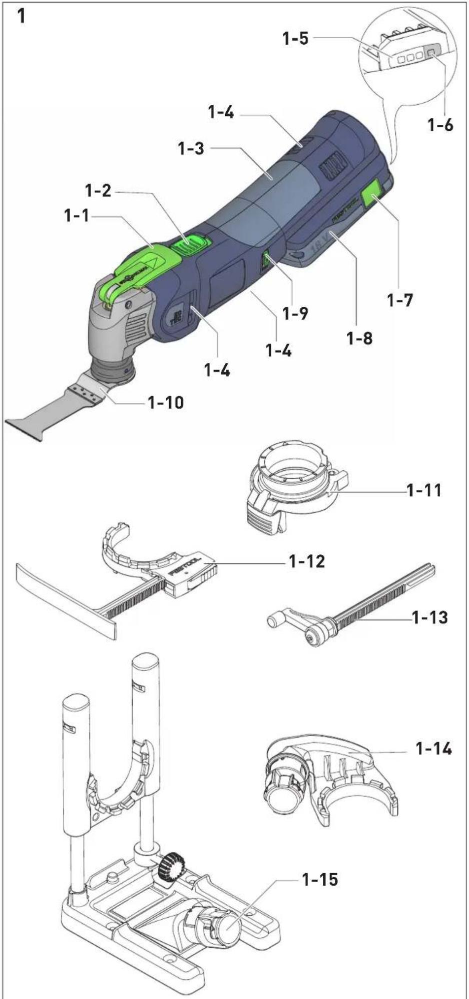
4
5
6
Akku-Oszillierer Cordless oscillator Scie oscillante sans fil
Seriennummer * Serial number * N° de série * (T-Nr.)
OSC 18 10041860
mit Akkupack/with battery pack/avec batterie BP 18 Li XX ASI/CI
de EG-Konformitätserklärung. Wir erklären in alleiniger Verantwortung, dass dieses Produkt allen ein-schlägigen Bestimmungen der folgenden Richtlinien einschließlich ihrer Änderungen entspricht und mit den folgenden Normen übereinstimmt:
en EC-Declaration of Conformity. We declare under our sole responsibility that this product is in conformity with all relevant provisions of the following directives including their amendments and complies with the following standards:
fr CE-Déclaration de conformité communautaire. Nous déclarons sous notre propre responsabilité que ce produit est conforme aux normes ou documents de normalisation suivants:
es CE-Declaración de conformidad. Declaramos bajo nuestra exclusiva responsabilidad que este producto corresponde a las siguientes normas o documentos normalizados:
it CE-Dichiarazione di conformità. Dichiariamo sotto la nostra esclusiva responsabilità che il presente prodotto e conforme alle norme e ai documenti normativi seguenti:
nl EG-conformiteitsverklaring. Wij verklaren op eigen verantwoordelijkheid dat dit produkt voldoet aan de volgende normen of normatieve documenten:
SV EG-konformitetsförklaring. Vi förklarar i eget ansvar, att denna produkt stämmer överens med följande normer och normativa dokument:
fi EY-standardinmukaisuusvakuutus. Va-kuutamme yksinvastuullisina, etta tuote on seuraavien standardien ja normatiivisten ohjeiden mukainen:
da EF-konformitetserklæring Vi erklærer at have alene ansvaret for, at dette produkt er i overensstemmelse med de følgende normer eller normative dokumenter:
nb CE-Konformitetserklæring Vi erklærer på eget ansvar at dette produktet er i overensstemmelse med følgende normer eller normative dokumenter:
Head of Productdevelopment

Ralf Brandt
Head of Productconformity
bar
| Range | Percentage (%) | |---|---| | 70-100% | 70-100 | | 40-70% | 40-70 | | 15-40% | 15-40 |
< 15% *
1 Symbols....14
2 Safety warnings....14
3 Intended use....15
4 Technical data.... 16
5 Parts of the device....16
6 Commissioning....16
7 Battery pack.... 16
8 Settings....16
9 Working with the machine.... 17
10 Acoustic warning signals.... 17
11 Accessories.... 18
12 Service and maintenance....18
13 Environment....19
14 General information....19
1 Symbols

Warning of general danger

Warning of electric shock

Read the operating instructions and safety instructions.

Wear protective goggles.

Wear ear protection.

Wear a dust mask.

Wear protective gloves.

Risk of pinching fingers and hands!

Danger area! Keep hands away!

Inserting the battery pack

Removing the battery pack

Do not dispose of it with domestic waste.

CE marking: Confirms the conformity of the power tool with the European Community directives.

Tip or advice

Handling instruction
2 Safety warnings
2.1 General power tool safety warnings

WARNING! Read all safety warnings, instructions, illustrations and specifica-
tions provided with this power tool. Failure to follow all instructions listed below may result in electric shock, fire and/or serious injury.
Save all warnings and instructions for future reference.
The term "power tool" in the warnings refers to your mains-operated (corded) power tool or battery-operated (cordless) power tool.
Follow the operating manual for the charger and the battery pack.
2.2 Machine-specific safety notices
- Hold the power tool by insulated gripping surfaces, when performing an operation where the cutting accessory may contact hidden wiring. Cutting accessory contacting a "live" wire may make exposed metal parts of the power tool "live" and could give the operator an electric shock.
- Use clamps or another practical way to secure and support the workpiece to a stable platform. Holding the workpiece by hand or against your body leaves it unstable and may lead to loss of control.
- Use appropriate detection devices to look for any hidden supply lines or consult your local utility company. If the insertion tool makes contact with live cables, it can result in fire and electric shock. Damage to a gas pipe can lead to an explosion. Penetration of a water pipe can result in damage to property.
- Harmful/toxic dust may be produced during your work (e.g. paint containing lead, certain types of wood and metal). Only qualified persons are permitted to handle materials containing asbestos. Aontact with or inhalation of this dust may pose a risk for the operating personnel or persons in the vicinity. Comply with the safety regulations that apply in your country.
Wear a P2 respiratory mask to protect health.


Wear suitable personal protective equipment: Ear protection, protective goggles, dust mask for work that generates dust, protective gloves for working with rough materials and for changing tools.
- Grip the electric power tool securely so that your body never comes into contact with the operating tool, especially when working with saw blades or cutting tools directed towards the grip area, for example. Contact with sharp blades or edges can result in injuries.
- After machining materials that contain gypsum: Clean the vents of the power tool and on/off switch using dry, oil-free compressed air. Otherwise, gypsum dust deposits may build up inside the power tool's housing and on the on/off switch and hard-en when exposed to humidity. This may impair the switching mechanism
- Wait until the power tool has come to a complete halt before placing it down. The insertion tool can get caught and lead to a loss of control of the power tool.
- Do not use power supply units or third-party battery packs to operate cordless power tools. Do not use third-party chargers to charge the battery packs. The use of accessories not expressly authorised by the manufacturer can result in electric shocks and/or serious accidents.
- Do not use the power tool in the rain or in damp surroundings. Moisture in the power tool may cause a short circuit and fire.
2.3 Metal processing

When processing metal, the following measures must be taken for safety reasons:
- Connect the machine to a suitable dust extractor.
- Regularly blow out the motor housing of the machine to remove dust deposits.

Wear protective goggles.
2.4 Emission levels
The levels determined in accordance with EN 62841 are typically:
Sound pressure level L _PA = 83 dB(A)
Sound power level L _WA = 93 dB(A)
Peak sound pressure level L_pC_peak = 97 dB(C)
Uncertainty K = 3 dB


CAUTION
Noise generated when working Risk of damage to hearing
▶ Use ear protection.
Vibration emission level a_h (vector sum for three directions) and uncertainty K measured in accordance with EN 62841:
- are used to compare machines.
- They are also used for making preliminary estimates regarding vibration and noise load during operation.
- They represent the primary applications of the power tool.

CAUTION
The emission values may deviate from the specified values. This is dependent on how the tool is used and the type of workpiece being machined.
▶ The actual load during the entire operating cycle must be evaluated.
▶ Depending on the actual load, suitable protective measures must be defined in order to protect the operator.
3 Intended use
Hand-held cordless oscillator designed for
- Sawing wood, plastic, glass-fibre reinforced plastic (GFRP), plasterboard and sawing sheet metal (max. 1 mm),
- Cutting out tile joints and window putty,
- Scraping away carpet residues and cutting elastic sealant,
- in a weatherproof environment,
– with the tools and accessories offered by Festool. - intended for use with BP Festool battery packs of the same voltage class.
Not suitable for removing windows from passenger cars, lorries and buses or renovating concrete joints.

The user is liable for improper or non-in-tended use.
4 Technical data
Cordless oscillator OSC 18
Motor voltage 18 V
Speed 10,000–19,500 rpm
Oscillation angle 2 x 2.0°
| Tool holder | StarlockMax |
| Compatible with | StarlockMax/Starlock-Plus/Star-lock |
Compatible with battery packs BP 18 from the series
Weight as per EPTA procedure 1.6 kg 01:2014:
5 Parts of the device
[1-1] Clamping lever for changing tools
[1-2] On/off switch
[1-3] Gripping surface
[1-4] Cooling air openings
[1-5] Capacity display
[1-6] Capacity display button on battery pack
[1-7] Button for releasing the battery pack
[1-8] Battery pack
[1-9] Speed control
[1-10] Tool
[1-11] Adapter*
[1-12] Depth stop with sliding shoe*
[1-13] Rotary depth stop*
[1-14] Dust extraction device*
[1-15] Positioning aid*
* Accessories shown or described are not always included in the scope of delivery.
The illustrations specified are located at the beginning and end of the operating instructions.
6 Commissioning
6.1 Switch on/off
The switch [1-2] is an on/off switch (I = ON, 0 = OFF).
When the battery pack is empty, or if there is a power failure or the mains plug is removed, move the on/off switch immediately to the Off position. This prevents uncontrolled restarting.
7 Battery pack
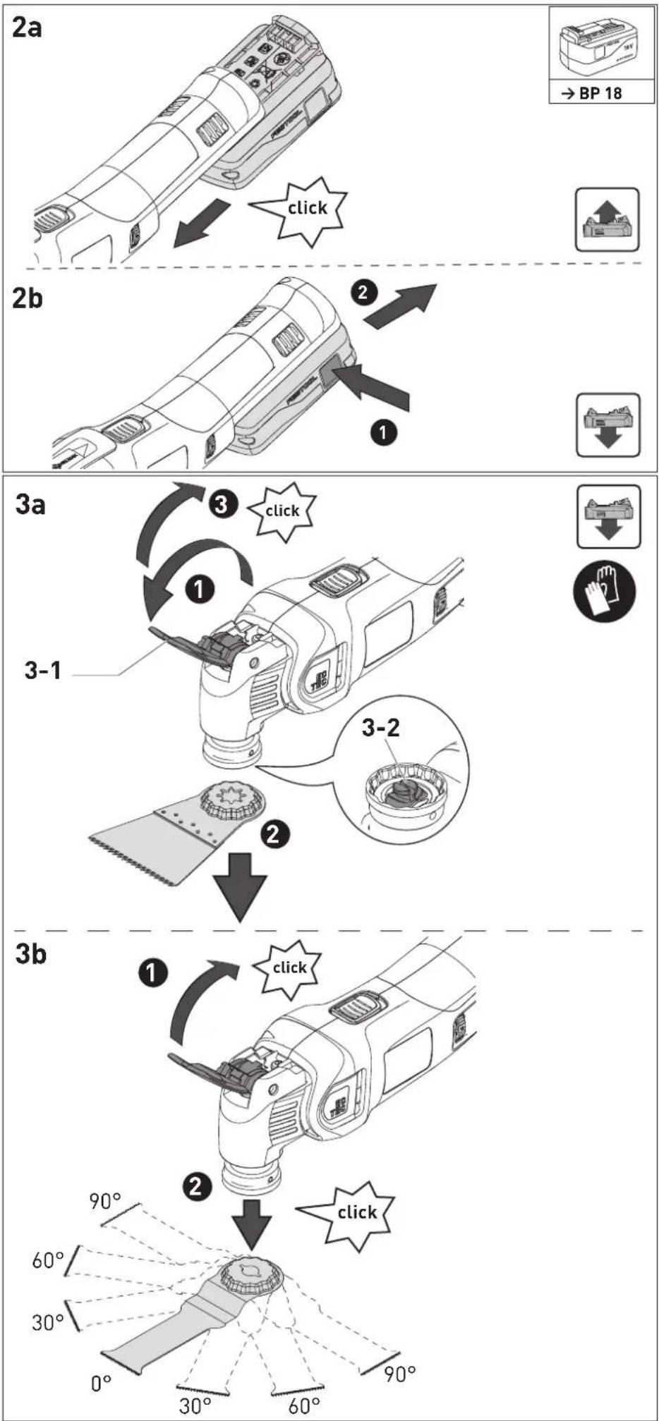
▶ Inserting the battery pack [2a]
▶ Removing the battery pack [2b]
7.1 Capacity display
The capacity display [1-5] indicates the charge of the battery pack for approx. 2 seconds after the button [1-6] is pressed:


* Recommendation: Charge the battery pack before any further use.
i Further information about the charger and battery pack with capacity indicator can be found in the corresponding operating manual.
8 Settings
WARNING
Risk of injury
- Remove the battery pack from the power tool before performing any work on the power tool.
8.1 Speed control
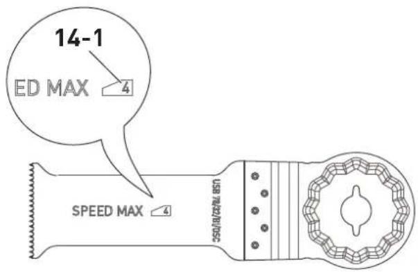
You can use the adjusting wheel to continuously adjust the speed within the speed range (see Section Technical data). This enables you to optimise the speed to suit the respective material. Please also note the specifications on the tools. If an insertion tool is only suitable up to a maximum speed, the maximum speed [14-1] is marked on the insertion tool (see Fig. [14]).
8.2 Changing the insertion tool


CAUTION
Hot and sharp tools Risk of injury
- Do not use any blunt or faulty insertion tools.
▶ Wear protective gloves.
▶ Carefully remove the protective resin from the cutting edge of new tools.

CAUTION
There is a risk of injury and negative impact on health associated with using tools that are not supplied or recommended by Festool.
Damage to machine caused by increased vibration load
▶ Always use original Festool tools.

CAUTION
Risk of crushing hands and fingers If you switch on the power tool when the clamping lever is open, the clamping lever is closed by spring force. Open clamping jaws are spring-loaded.
▶ Never switch on the power tool with the clamping lever open.
▶ Never reach into the area around the clamping jaws.
Removing the insertion tool [3a]
▶ Open the clamping lever [3-1].
The insertion tool drops down.
- Close the clamping lever until it clicks into place.
If the power tool switches on without the insertion tool, the clamping jaws [3-2] may open. This makes a popping sound.
Inserting the insertion tool [3b]
If the clamping jaws [3-2] are open, open and close the clamping lever [3-1].
- Close the clamping lever until it clicks into place.
▶ Push the device onto the tool until it clicks into place.
The tool can be offset in 30^ increments and secured in the most effective working position.
① The protection (against accidental contact) on the saw blade may become twisted if wear has occurred, see fig. [4]
9 Working with the machine
Observe the following information:
- Only guide the power tool towards the workpiece when it is switched on.
- A significant increase in the force required to advance the machine and slow working progress are indicators that the blades are worn.
- Hold the power tool by the gripping surface [1-3] with both hands to ensure safe guidance. Do not cover the cooling air openings [1-4] with your hand. Otherwise there is a risk of the machine overheating.
- Do not hold the power tool by the battery pack.
- Always secure the workpiece in such a way that it cannot move during machining.
10 Acoustic warning signals
If the power tool switches off due to one of the following operating states, a warning signal sounds when switching on the tool and the power tool switches off again.
Battery pack not accepted
- Insert the correct battery pack model.
Battery pack empty
- Change the battery pack.
- Charge the battery pack.
Battery pack fault
- Change the battery pack.
- Use the charger to check that the battery pack is fully functional once it has cooled down.
Battery pack overheated
- Let the battery pack cool down.
Power tool overheated
- You must allow the power tool to cool down before starting it up again.
Power tool fault
- Contact a Festool service workshop or specialist dealer.
Power tool jammed
- Eliminate the cause of the jam.
① If the power tool switches of when it becomes jammed, no warning signal sounds.
11 Accessories

WARNING
Risk of injury
- Remove the battery pack from the power tool before performing any work on the power tool.
Always use original Festool tools and accessories. Using low-quality tools or accessories from other manufacturers may increase the risk of injury and seriously unbalance the machine, decreasing the quality of the working results and accelerating power tool wear.
Refer to the Festool catalogue for the order numbers of accessories and tools or find them online at www.festool.co.uk.
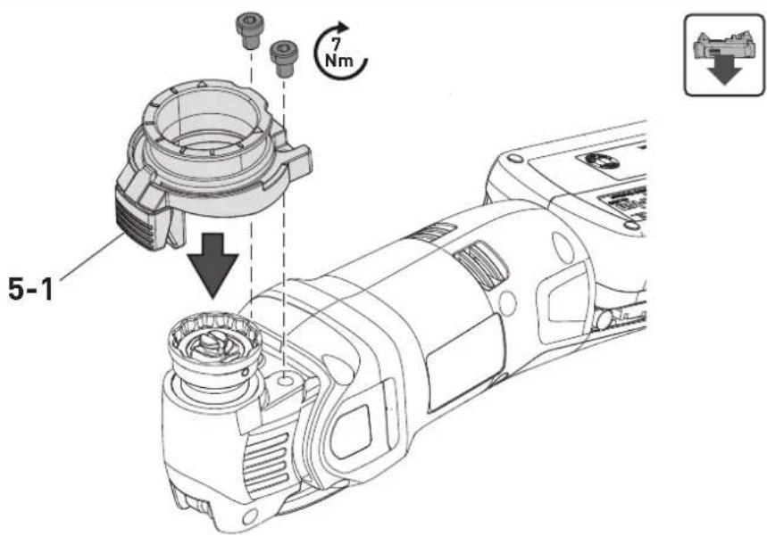
11.1 Mounting the adapter [5]
A depth stop, dust extraction device and positioning aid can be mounted on the adapter. Using the detent button [5-1] , these can be offset in 30^ increments in line with the tool.
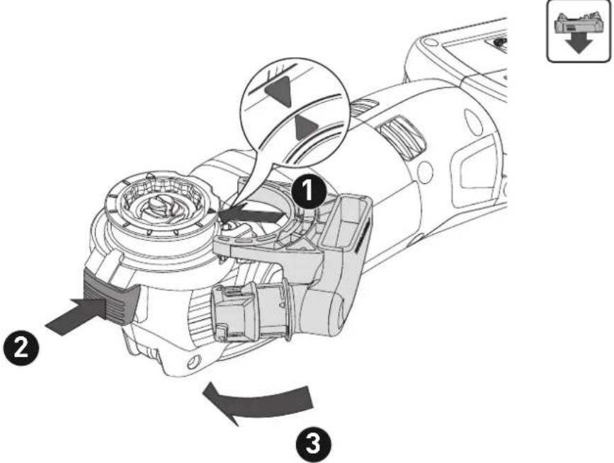
11.2 Dust extraction device [6]
▶ Mount the adapter [5].
▶ Attach the dust extraction device.
▶ Connect the suction hose.
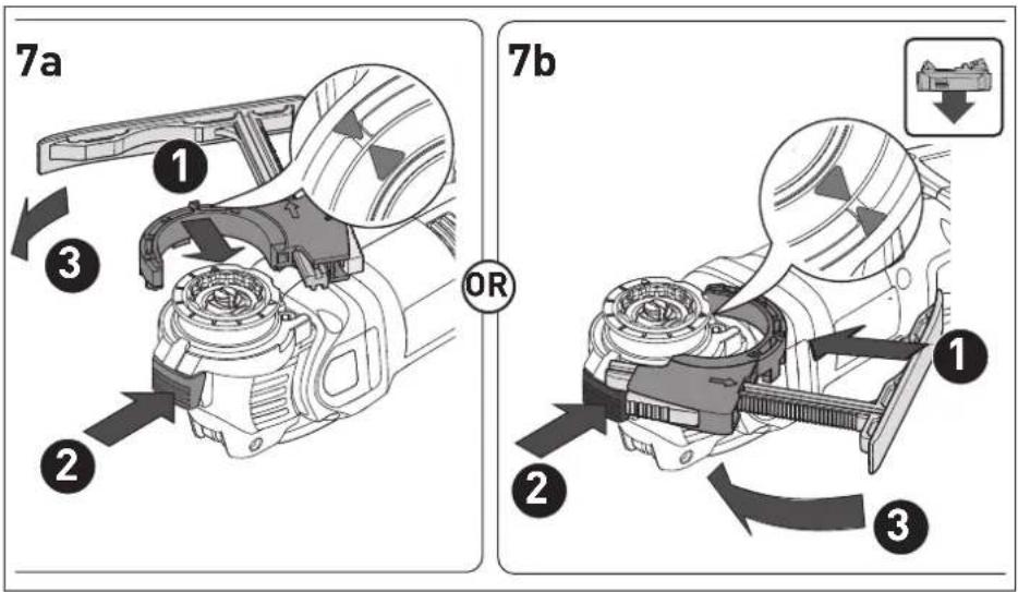
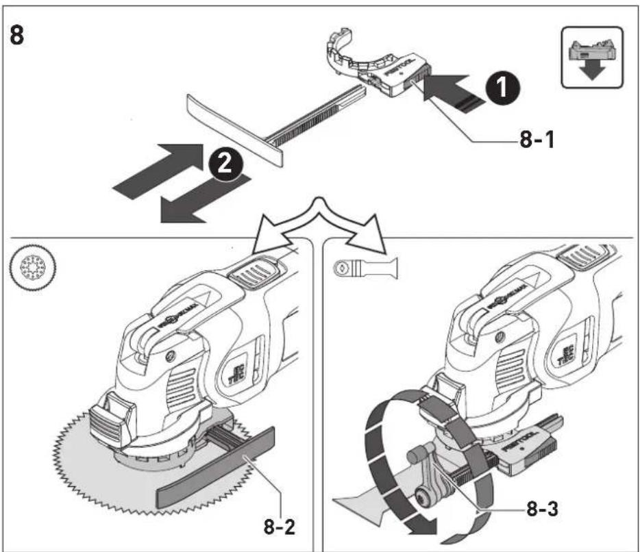
11.3 Depth stop [7+8]
▶ Mount the adapter [5].
▶ Attach the depth stop - [7a] or [7b].
▶ Engage the adjusting lever [8-1] to set the cutting depth.
i Select the correct depth stop for the tool and replace if necessary:
![FESTOOL OSC 18 - Depth stop [7+8] - 1](/content/2026/03/570626/images/f6927539d59c849a1db8a81d211595af81d487a16984735a07ef5a9e3f08259c.jpg)
Round tools Sliding shoe [8-2]
![FESTOOL OSC 18 - Depth stop [7+8] - 2](/content/2026/03/570626/images/2a96045da25ec4bf34550b496aaf0e06e9e2567c54f6ad9d9b8656e9d6238695.jpg)
Cutting blade Rotary depth stop [8-3]
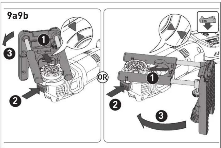
11.4 Positioning aid [9+10+11+12]
![FESTOOL OSC 18 - Positioning aid [9+10+11+12] - 1](/content/2026/03/570626/images/0ca425e69c3c27edd5a7036dd2541185bee6a2b196bf95e7624cfd4a2e22ec96.jpg)
WARNING
Sharp tools
Pinching and cutting injuries
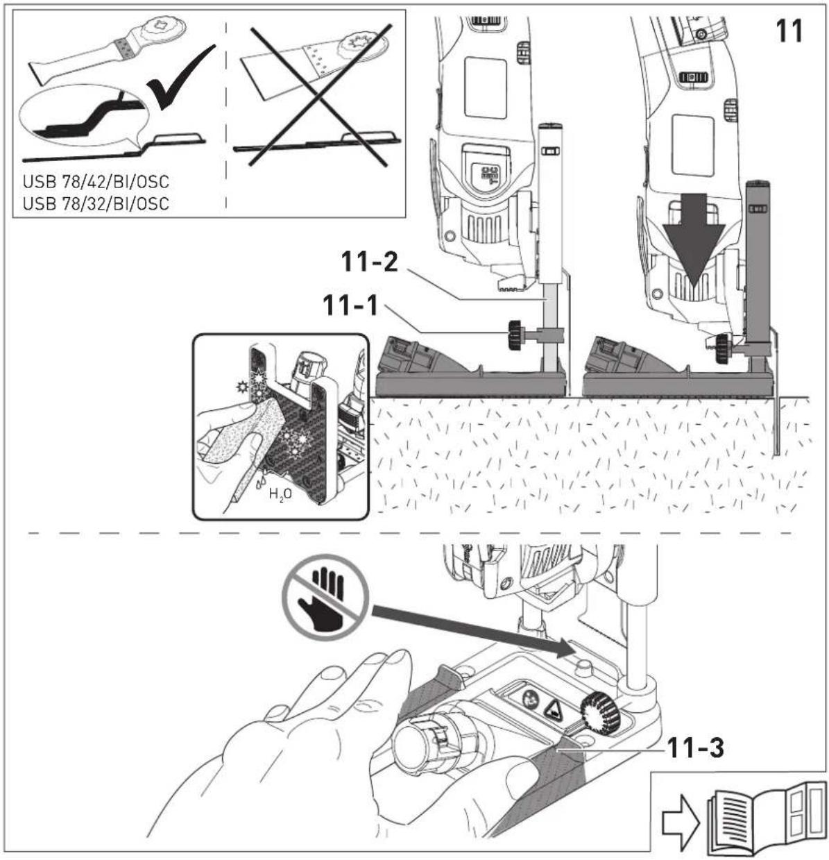
▶ Always rest your fingers on the defined gripping surfaces [11-3].
▶ Always use the saw blades indicated in Fig. [11]. Do not use short saw blades.

WARNING
Risk of accident, electric shock If the tool comes into contact with live cables, an electric current may be diverted through metal components in the tool and result in electric shock.
- Hold the power tool by the insulated gripping surfaces when performing work that may pose a risk of cutting into hidden power cables.
Using the positioning aid
▶ Mount the adapter [5].
▶ Attach the positioning aid – [9a] or [9b].
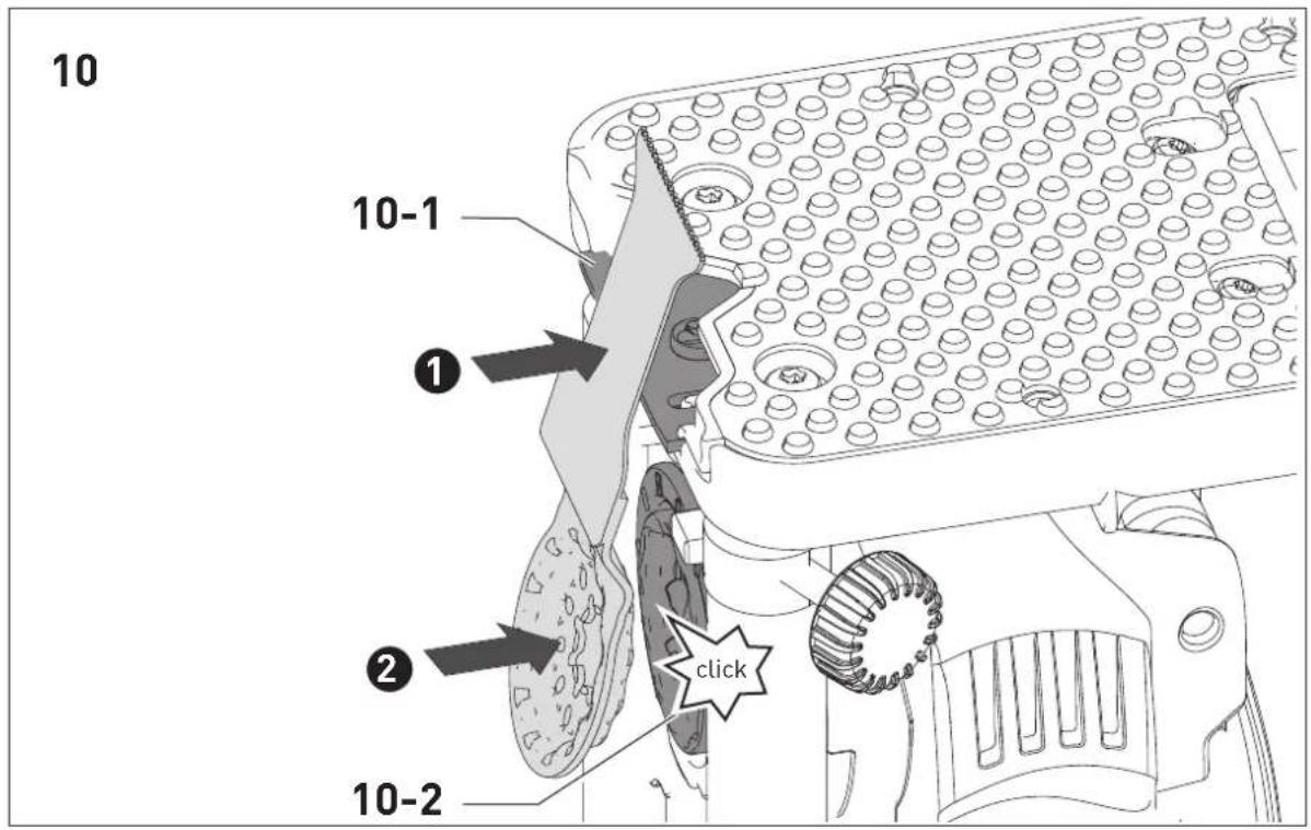
▶ First place the application tool on the saw blade guide [10-1], then push it into the holder [10-2] until it engages. This is necessary to ensure that the application tool is positioned correctly on the saw blade guide.
▶ Adjust the cutting depth [11-1].
Always tighten the cutting depth adjustment [11-1].
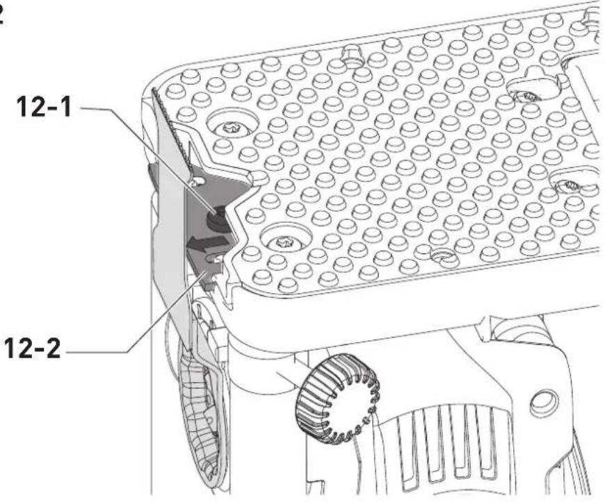
Readjusting the saw blade guide
First check to ensure that the application tool has been inserted in the correct order (see figure [10]). If the saw blade is still not positioned on the saw blade guide, take the following steps:
▶ Set the cutting depth [11-1] to the maximum depth. Tighten the cutting depth adjustment [11-1].
▶ Loosen the screw [12-1] on the saw blade guide [12-2].
▶ Move the saw blade guide to the saw blade.
▶ Tighten the screw [12-1] on the saw blade guide.
12 Service and maintenance


WARNING
Risk of injury, electric shock
▶ Always remove the battery pack from the power tool before performing any maintenance or service work.
▶ All maintenance and repair work which requires the motor housing to be opened should always be carried out by an authorised service workshop.

Customer service and repairs must only be carried out by the manufacturer or service workshops. Find the nearest address at: www.festool.co.uk/service
Always use original Festool spare parts. Order no. at: www.festool.co.uk/service
To ensure constant air circulation, always keep the cooling air openings in the motor housing clean and free of blockages.
Keep the contacts on the power tool, charger and battery pack clean.
When machining materials that contain gypsum, dust deposits may build up inside the power tool and on the on/off switch and harden when exposed to humidity. This may impair the switching mechanism. After each machining process, blow out the inside of the power tool through the vents and the on/off switch using dry, oil-free compressed air.
12.1 Information on the positioning aid
Clean any dust deposits from guides [11-2] and contact surfaces. Oil the guides regularly and lightly with resin-free oil (e.g. sewing machine oil).
13 Environment

Do not dispose of the device in the household waste! Recycle devices, accessories and packaging. Observe appli-national regulations.
EU only: In accordance with the European Directive on waste electrical and electronic equipment and implementation in national law, used power tools must be collected separately and handed in for environmentally friendly recycling.
Information on REACH: www.festool.com/reach
14 General information
Imported into the UK by
Festool UK Ltd
1 Anglo Saxon Way
Bury St Edmunds
IP30 9XH
Great Britain
14.1 Bluetooth®
The Bluetooth ^® word mark and the logos are registered trademarks of Bluetooth SIG, Inc.; they are used by TTS Tooltechnic Systems AG & Co. KG, and therefore by Festool, under licence.
Sommaire
natural_image
Four horizontal bars with varying internal patterns and a small circular icon at the bottom (no text or symbols)70-100 %
40-70%
15-40%
< 15 % *
| 70-100% | |
| 40-70% | |
| 15-40% | |
| < 15% * |
natural_image
Four rectangular battery cells with varying internal segments and a highlighted internal component (no text or symbols)70-100%
40-70%
15-40%
< 15% *
bar
| Range | Percentage (%) | |---|---| | 70-100% | 70-100 | | 40-70% | 40-70 | | 15-40% | 15-40 | | < 15% * | < 15% |2.3 Metallbearbeiding

bar
| Range | Percentage (%) | |---|---| | 70-100% | 70-100 | | 40-70% | 40-70 | | 15-40% | 15-40 | | < 15% * | < 15% |natural_image
Four horizontal bars with black rectangular blocks and a small circular component inside, no text or symbols present.70-100%
40-70%
15-40%
< 15% *
natural_image
Four horizontal bars with black and white segments, one highlighted with a light bulb (no text or symbols)70—100%
40—70%
15—40%
< 15 % *
natural_image
Four horizontal bars with black rectangular blocks, one partially filled and a small circular mark below (no text or symbols)70-100%
40-70%
15-40%
< 15% *
Declaration of Conformity
We as the manufacturer Festool GmbH, Wertstraße 20, 73240 Wendlingen, Germany declare under our sole responsibility that the product(s):
Designation:
Designation of Type(s):
Serial number(s) 1):
Cordless oscillator
OSC 18
10041860
fulfills all the relevant provisions of the following UK Regulations:
S.I. 2008/1597
S.I. 2016/1091 ^2
S.I. 2017/1206 ^3
S.I. 2012/3032
Supply of Machinery (Safety) Regulations 2008
Electromagnetic Compatibility Regulations 2016
Radio Equipment Regulations 2017
Restriction of the Use of Certain Hazardous Substances in Electrical and Electronic Equipment Regulations 2012
and are manufactured in accordance with the following designated standards:
• BS EN 62841-1: 2015
• BS EN 62841-2-4: 2014
• BS EN 62841-2-11:2016+A1:2020
• BS EN 55014-1:2017 ^2
• BS EN 55014-2:2015 ^2)
• EN 300 328:2016 V2.1.1 ^31
• EN 301 489-1:2017 V2.1.1 ^3)
• EN 301 489-17:2017 V3.1.1 ^3)
• BS EN IEC 63000:2018
11 in the specified serial number range (S-Nr.) from 400000000 - 499999999
21 valid in combination with battery pack BP 18 Li 5,2 AS, BP 18 Li 6,2 AS, BP 18 Li 3,1 C, BP 18 Li 4,0 HPC-AS
3) valid in combination with Bluetooth® battery pack BP 18 Li 5,2 ASI, BP 18 Li 6,2 ASI, BP 18 Li 3,1 Cl, BP 18 Li 4,0 HPC-ASI

Place and date of declaration: Wendlingen, 31.03.2021
Signed on behalf of and in name of Festool GmbH
$$ p p ^ {n} \cdot p s A $$
Markus Stark
Head of Productdevelopment
i.V. Q. Brandt
Ralf Brandt
Head of Productconformity
12
13
| VK a h K Typ | ||||
| VK 1 | < 5 m/s2 | 1,5 |  | SSB 90/OSC/DIA |
| HSB 100/Bi/OSC | ||||
| SSB 32/OSC | ||||
| < 6 m/s2 | 1,5 | [4w0d] | HSB 50/35/J/OSC | |
| USB 50/35/Bi/OSC | ||||
| VK 2 | < 7 m/s2 | 1,5 | [4w0d] | USB 78/32/Bi/OSC |
| HSB 50/65/J/OSC | ||||
| USB 78/42/Bi/OSC | ||||
| USB 50/65/Bi/OSC | ||||
| SSP 52/OSC | ||||
14