TXA802SR - Receiver Monacor - Free user manual and instructions
Find the device manual for free TXA802SR Monacor in PDF.
User questions about TXA802SR Monacor
0 question about this device. Answer the ones you know or ask your own.
Ask a new question about this device
Download the instructions for your Receiver in PDF format for free! Find your manual TXA802SR - Monacor and take your electronic device back in hand. On this page are published all the documents necessary for the use of your device. TXA802SR by Monacor.
USER MANUAL TXA802SR Monacor
for Audio Transmission System
863–865 MHz
natural_image
Front view of a black MONACOR wireless router with two antennas and a digital display (no readable text or symbols beyond branding)TXA-802SR
2-Channel Receiver for Audio Transmission System
These instructions are intended for users without any specific technical knowledge. Please read these instructions carefully prior to operation and keep them for later reference.
All operating elements and connections described can be found on page 2.
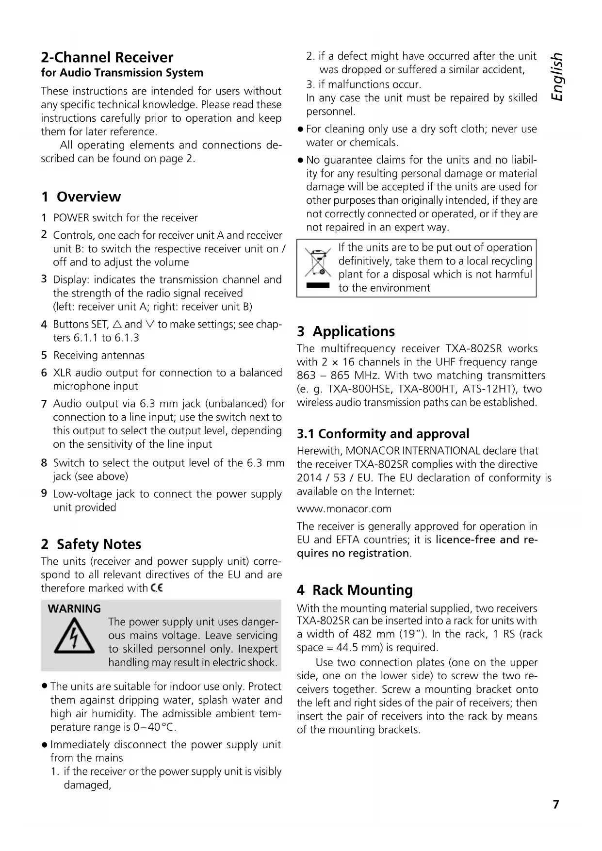
1 Overview
1 POWER switch for the receiver
2 Controls, one each for receiver unit A and receiver unit B: to switch the respective receiver unit on / off and to adjust the volume
3 Display: indicates the transmission channel and the strength of the radio signal received (left: receiver unit A; right: receiver unit B)
4 Buttons SET, and to make settings; see chapters 6.1.1 to 6.1.3
5 Receiving antennas
6 XLR audio output for connection to a balanced microphone input
7 Audio output via 6.3 mm jack (unbalanced) for connection to a line input; use the switch next to this output to select the output level, depending on the sensitivity of the line input
8 Switch to select the output level of the 6.3 mm jack (see above)
9 Low-voltage jack to connect the power supply unit provided
2 Safety Notes
The units (receiver and power supply unit) correspond to all relevant directives of the EU and are therefore marked with C€
WARNING
The power supply unit uses dangerous mains voltage. Leave servicing to skilled personnel only. Inexpert handling may result in electric shock.
- The units are suitable for indoor use only. Protect them against dripping water, splash water and high air humidity. The admissible ambient temperature range is 0–40°C.
- Immediately disconnect the power supply unit from the mains
-
if the receiver or the power supply unit is visibly damaged,
-
if a defect might have occurred after the unit was dropped or suffered a similar accident,
-
if malfunctions occur.
In any case the unit must be repaired by skilled personnel. -
For cleaning only use a dry soft cloth; never use water or chemicals.
- No guarantee claims for the units and no liability for any resulting personal damage or material damage will be accepted if the units are used for other purposes than originally intended, if they are not correctly connected or operated, or if they are not repaired in an expert way.

If the units are to be put out of operation definitively, take them to a local recycling plant for a disposal which is not harmful to the environment
3 Applications
The multifrequency receiver TXA-802SR works with 2 × 16 channels in the UHF frequency range 863 – 865 MHz. With two matching transmitters (e.g. TXA-800HSE, TXA-800HT, ATS-12HT), two wireless audio transmission paths can be established.
3.1 Conformity and approval
Herewith, MONACOR INTERNATIONAL declare that the receiver TXA-802SR complies with the directive 2014 / 53 / EU. The EU declaration of conformity is available on the Internet:
www.monacor.com
The receiver is generally approved for operation in EU and EFTA countries; it is licence-free and requires no registration.
4 Rack Mounting
With the mounting material supplied, two receivers TXA-802SR can be inserted into a rack for units with a width of 482 mm (19"). In the rack, 1 RS (rack space = 44.5 mm) is required.
Use two connection plates (one on the upper side, one on the lower side) to screw the two receivers together. Screw a mounting bracket onto the left and right sides of the pair of receivers; then insert the pair of receivers into the rack by means of the mounting brackets.
5 Setting the Receiver into Operation
1) Place the receiving antennas (5) in a vertical position.
2) To connect the receiver to the subsequent audio unit, e. g. mixer or amplifier, use one of the two audio outputs:
– either connect the XLR output (6) to a balanced microphone input
- or connect the unbalanced 6.3 mm jack (7) to a line input; depending on the sensitivity of the line input, set the switch (8) next to the output to "LOW" (low output level) or "HIGH" (high output level).
3) For power supply, connect the power supply unit provided to the low-voltage jack (9) and to amainssocket(230V/50Hz).
Note: The power supply unit has a low power consumption even when the receiver is switched off; therefore, disconnect the power supply unit from the mains socket when the receiver is not operated for a longer period of time.
6 Operating the Receiver
To switch on the receiver, set the POWER switch (1) to "ON". To switch off the receiver, set the POWER switch to "OFF".
Each receiver unit (A and B) provides a control (2) to switch it on and off and to adjust the volume. To switch a receiver unit on, turn the control clockwise from the position "OFF". The left half of the display (3) applies to receiver unit A, the right half of the display applies to receiver unit B. When a receiver unit has been switched on, the corresponding half of the display will indicate the transmission channel.
Note: To briefly indicate the radio frequency for a receiver unit, briefly press the button (for unit A) or (for unit B).
6.1 Establishing wireless transmission paths
The distance between the transmitter and the receiver should be at least 2 m; the distance between the individual transmitters should be at least 0.5 m.
1) Set the transmission channels for the receiver units A and B via channel scan or manually (chapter 6.1.1 or 6.1.2). Do not switch on the two corresponding transmitters for the time being. If one or more segments of a reception indicator light up on the display, interference signals or signals from other transmitters are
being received. In this case, select a different channel for the respective receiver unit.
2) Switch on the transmitters and set them to the channel of receiver unit A and receiver unit B respectively. The segment bars A and B on the display will indicate the strength of the radio signals received.
Use the controls to adjust the volume for each receiver unit.
If no reception is indicated or if the reception is poor, check if:
- the (rechargeable) batteries of the transmitter are discharged
- the reception is disturbed by metal objects or other high-frequency sources
– the distance (transmitter — receiver) is too long
– the reception can be improved by turning the receiving antennas (5)
– the squelch value is too high (chapter 6.1.3)
Note concerning multichannel operation:
The number of channels to be used in parallel depends on the conditions at the place of application (e. g. on interference due to other wireless systems or high-frequency sources such as fluorescent lamps). In ideal conditions, up to four channels can be operated at the same time without mutual interference. Two examples of a suitable channel selection for four wireless transmission paths:
Example 1:
channel 01 – channel 03 – channel 06 – channel 12
Example 2:
channel 06 – channel 09 – channel 15 – channel 16
6.1.1 Channel scan
Keep the buttons and simultaneously pressed for approx. 1 second until SCAn appears on the display. The scan will start: The receiver units A and B will be set to free channels without mutual interference. If no free channels are found, the set channels will be kept.
Note: It is also possible to perform a channel scan for just one receiver unit: Keep the appropriate arrow key ( for unit A, for unit B) pressed for approx. 1 second until SCAn appears on the display.
Operation with two receivers TXA-802SR:
When two receivers TXA-802SR are simultaneously operated and the four transmission channels are to be set via channel scan, change the group setting of both receivers:
1) Switch off the receiver units A and B. Then keep the button SET pressed, while switching on a receiver unit. The display will indicate the current group setting F1 (with the digit flashing).
2) Use the button or to switch to F2.
3) To exit the group setting mode and to go to the squelch setting mode (chapter 6.1.3), press the button SET. To exit the squelch setting mode, press the button SET.
Note: The setting modes will be automatically exited after 5 seconds if no button is pressed. Any settings you may have made will be saved.
Perform the channel scan for the first receiver, switch on the appropriate two transmitters and set them accordingly. Leave the two transmitters switched on so that the channels already used will be skipped during the channel scan for the second receiver. Then perform the channel scan for the second receiver, switch on the two appropriate transmitters and set them accordingly.
6.1.2 Manual channel selection
If both receiver units A and B are switched on:
1) Keep the button SET pressed until the channel indication for receiver unit A starts flashing on the display.
2) Use the button or to select the channel for receiver unit A, then press the button SET to confirm.
3) The channel indication for receiver unit B starts flashing on the display. Use the button or to select the channel for receiver unit B, then press the button SET to confirm.
If only one receiver unit A or B is switched on:
Keep the button SET pressed until the channel indication starts flashing on the display. Select the channel with the button or and then confirm with the button SET.
If a channel is not confirmed within 10 seconds with the button SET, the setting mode will be exited and the channel previously set will be kept.
Note: The receiver units A and B cannot be set to the same channel.
6.1.3 Setting the squelch
The squelch function will mute the respective receiver unit when the level of the radio signal falls below the threshold value adjusted. Thus, interference signals will not cause noise when the transmitter is switched off or when its radio signal is insufficient: If the levels of the interference signals are below the threshold value, the receiver unit will be muted.
A high threshold value offers high interference resistance, but it will also reduce the transmission range. Thus, when the reception is good, a high threshold value can be used; however, when the transmitter and the receiver are far apart, a low threshold value is recommended.
1) Switch off the receiver units A and B. Then keep the button SET pressed, while switching on a receiver unit. The display will indicate the group setting (For, with the digit flashing).
2) To exit the group setting mode and to go to the squelch setting mode, press the button SET: The display will indicate 59 (for "Squelch") and the current value (flashing).
3) Use the button or to set the value (level 7 = highest threshold value).
4) To exit the squelch setting mode, press the button SET.
Note: The setting modes will be automatically exited after 5 seconds if no button is pressed. Any settings you may have made will be saved.
7 Specifications
| Radio frequencies | |||
| Channel | Frequency Channel | Frequency | |
| 01 863. | 1 MHz 09 863.2 | MHz | |
| 02 864. | 1 MHz 10 864.2 | MHz | |
| 03 863. | 6 MHz 11 863.7 | MHz | |
| 04 864. | 6 MHz 12 864.7 | MHz | |
| 05 863. | 3 MHz 13 863.4 | MHz | |
| 06 864. | 3 MHz 14 864.4 | MHz | |
| 07 863. | 8 MHz 15 863.9 | MHz | |
| 08 864. | 8 MHz 16 864.9 | MHz | |
Output level
XLR (bal.): 30 mV
6.3 mm jack (unbal.): .... 730 mV (HIGH) 80 mV (LOW)
Power supply: ....... via PSU supplied and connected to 230V/50Hz
Dimensions (W × H × D): .. 215 × 44 × 210 mm (w / o antennas and feet)
Weight: 1.2 kg
Subject to technical modification.