SCC 255 W - Saw Stayer - Free user manual and instructions
Find the device manual for free SCC 255 W Stayer in PDF.

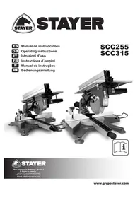
| Product type | Radial miter saw (miter circular saw) |
| Brand | Stayer |
| Model | SCC 255 W |
| Blade diameter | 255 mm |
| Rated voltage | 230–240 V / 110–120 V, 50/60 Hz |
| Frequency | 50/60 Hz |
| Electrical protection class | II (double insulation) |
| IP protection rating | IP20 |
| Required disc type | Original STAYER EN 847-1 discs |
| Cutting capacity at 90° (estimated) | Up to 70 mm |
| Horizontal miter range | ±45° |
| Vertical miter range | 0° to 45° |
| Main functions | Straight cut, horizontal and vertical miter cut, use as circular saw (upper table) |
| Safety | Separation blade, upper and lower guards, safety stop in case of power outage |
| Dust extraction system | Outlet for bag (included) or adapter for vacuum cleaner |
| Included accessories | Cutting guide, dust bag, adapter, jaws |
| Compatible materials | Hardwood, softwood, particle board, fiberboard, PVC pipes |
| Regular maintenance | Cleaning with brush and compressed air; complete overhaul every 2000 h or 2 years |
| User lubrication | None required |
| Warranty | Manufacturing defects (see warranty card) |
Frequently Asked Questions - SCC 255 W Stayer
User questions about SCC 255 W Stayer
0 question about this device. Answer the ones you know or ask your own.
Ask a new question about this device
Download the instructions for your Saw in PDF format for free! Find your manual SCC 255 W - Stayer and take your electronic device back in hand. On this page are published all the documents necessary for the use of your device. SCC 255 W by Stayer.
USER MANUAL SCC 255 W Stayer
Pinto (Madrid) Spain.
15. Garantía
Tarjeta de Garantía
$$ = \text {P e s o}. $$
L_pA = Nivel de presion acustica.
28320 PINTO (MADRID)
Tel.: +34 91 691 86 30 / Fax: +34 91 691 91 72
This manual is consistent with the date of manufacture of your machine, you will find information on the technical data of the machine acquired manual check for updates of our machines on the website: www.grupostayer.com
1. Provided uses of the machine
This tool has been solely and exclusively provided for:
- Stationary works on flat and stable surface
- Working on hard and soft wooden pieces
- Working on chipboard pieces
- Working on fiberboard pieces
- Working on PVC tubes
- Making rectilinear cuts along the length and width of the workpiece
- Making horizontal litre-cuts between -45^ and 45^ .
- Making vertical metre-cuts between 90^ and 45^
Refer to the limits regarding the size of the workpiece in corresponding chapter 11.
2. Unpackaging and assembling
Unpackaging
- Cut the seal and open the box.
- Withdraw upper cardboard stoppers
- Extract the box by firmly grasping the operating head and the motor body using both hands so as to balance the weight
- Extract the box with the accessories
- Extract the documentation
- Preserve the cardboard box, the stoppers thereof and the documentation permanently in an inventoried safe environment being easily accessible and known to the machine operator.
Packaging
Operation 1: Securing, folding and fastening the operating head::
- Place upper head at horizontally 0^ .
- Place upper head at vertically 90^ .
- Arrange protector such that it contacts the cutting bench.
- Lower head to the limit and position it to be able to lock it with the button.
Operation 2: Packaging the machine
- Locate the cardboard box.
- Locate documentation.
- Firmly grasp the machine by its operating head and motor body.
- Place the machine over the 4 circular recesses of the bottom of the box.
- Store documentation of the machine.
- Position upper cardboard stoppers.
Close the box and fix it with sealing tape.
3. Setting or fastening the machine in a stable position
- The working area where the machine is being arranged must mandatorily be safe.
- Support tool in a stable position on an even surface.
- The base of the litre saw has four holes for firmly fastening the machine to the working bench. It is strongly recommended to fix the machine to the bench by means of the pertinent screws and nuts.
4. Connection to the grid, wiring, fuses, socket type for the jack and requirements for grounding
- For supplying electrical power to the machine, connect the Schuko Jack to a standard socket capable of supplying a minimum of 2500 VA.
- The internal wiring of the machine is completely terminated so that no wiring is needed when installing it.
- The machine does not have fuses although the use of a dedicated magnetothermal switch is recommended as a protection for the machine.
- The machine has a class II electrical equipment so that it does not make use of the grounding of the electrical installation.
5. Illustrated description of functions
- Angle selector knob.
- Lower table protector.
- Button to unlock head.
- Level adjustments of upper table.
- Locking knob for lower head.
- Lowering limit adjustment of disc.
- Inclination limit adjustment of disc 0^ / 45^
- Inclination adjustment of the disc.
- Limit adjustment of the disc angle at +45^ / -45^
- Insertion of long cutting support (only SCC315).
- Insertion of clamps.
6. Limitations regarding environmental conditions
The IP degree of this machine is 20. This machine is protected against its dangerous parts being accessed by a finger and against solid foreign particles having diameters of 12^5mm and more. This machine does not have any kind of protection against the entry of water so that its use in exterior or interior environmental conditions with a risk of precipitations is forbidden.
7. List of contents
- Provided uses of the machine
- Unpackaging and assembling
- Setting or fastening the machine in a stable position
- Connection to the grid, wiring, fuses, socket type for the jack and grounding conditions
-
Illustrated descriptions of functions
-
Limitations regarding environmental conditions
- List of contents
- Settings and testing
- Changing tools
- Fixing for operation
- Limits regarding the workpiece size
- General instructions for use
- Dust extraction
- Regular cleaning, maintenance and greasing.
- Guarantee.
- Disposal.
- Technical specifications
- Declaration of conformity
8. Settings and testing
Warning!
Before any intervention on the electrical tool remove jack from power socket.
If the machine has been subject to prolonged or intense use, it must be checked and adjusted so as to ensure the machine's correct quality of service and safety.
This requires knowledge, experience and special tools. The official technical service of Stayer Iberica S.A. will carry out that work for you in a quick thorough and inexpensive manner.
Adjusting the locking in the lower resting position
Verification
- Levantar el cabezal apretando el botón 3.
- Lower the head until reaching the stop.
- Press button 5. If it is well adjusted, the bolt of the button should smoothly enter up to the stop. If not, proceed to adjust it.
Adjustment
- Loosen the fastening screw of the locking screw 6.
- Lower the head to the lower stop.
- Tighten or loosen screw 6 until the knob 5 penetrates the stop smoothly.
- While the screw is held, tighten the nut of the perpendicular restraint.
Adjust the angle of the horizontal litre joint to +45^
Verification
- Move the head horizontally until it is locked at +45^ .
- Verify that the horizontal angle indicator marks exactly 45^ . If not, proceed to the adjustment.
- Repeat the same sequence for the horizontal angle at -45^
Adjustment
- Move the head set and the cutting table horizontally until it locks at 45^ .
- Work on the screws 9 until obtaining exactly 45^ .
- Repeat the same sequence for the horizontal angle at -45^ .
Adjust the vertical litre joint angle to 90^ and 45^ .
Verification
- Release the vertical adjustment of the head by loosening 8.
- Move the head to the right stop (90^) or left stop (45^) .
- Check the angle by means of a duly calibrated angular template or a compass (minimum precision +5^ ) presenting one of its surfaces on the lower table and the other on the cutting disc. Use light as contrast to see the adjustment.
- If the face of the template does not adjust exactly with the disc or if the direct measurement of the compass shows a deviation greater than + - 20^ proceed to the adjustment.
Adjustment
- Work on the adjustment screws 7 until reaching a measurement of 90^ or 45^ .
Adjust the separator blade
It is black metallic plate that is behind the upper part of the disc. Its function is to impede the joining of the pieces that are being cut and flying out towards the user's face.
In order to verify and adjust, access the blade, performing step 1 of the section 'Change cutting disc' and verify the alignment of the blade with the disc and that the distance between the teeth of the disc and the blade surface is 2 mm. If it is not, adjust with the two screws that hold the blade.
9. Tool change
Warning!
Before any intervention in the electric tool, remove the plug from the outlet.
Warning!
It is mandatory to use discs according to EN 847-1 STAYER originals.
Change of cutting disc
- Remove the upper table. To do this, remove the support screws of the upper aluminium table, the three crosshead screws of the upper black safeguard and the screw of the interior rocker arm of the safeguard.
- Hold the cutting disc with a piece of wood against its teeth and loosen the screw rotating it to the right.
- Extract the disc from above and install the new one following the two previous sections in reverse order.
10. Fixing for operation
Whenever possible, the workpiece must be fixed in such a manner that the hand does not intervene. During the cut, keep the workpiece fixed to the support. ALL MACHINES ARE PREPARED FOR MOUNTING CLAMPS ALLOWING FASTENING THE PROFILE IN A SAFE MANNER.
To avoid deformations of the workpieces during fixing thereof, the use of wooden profiles being easily applicable to the movable jaws of the clamps is advised. Clamps can be easily extracted and leave the working surface totally clear.
For cutting long workpieces under safe conditions it is essential to hold them with additional supports.
11. Limits regarding the workpiece size
Limits for all models as included in the present manual.
Pag. 4.
12. General instructions for use
Warning!
- Do NOT use the machine if it is in a bad condition, or lacks parts including the prescribed upper guards (the illustrations of the present manual may be used as an orientative guide). Unplug it, remove it from the working area and immediately send it to an authorized technical service.
- Know and comply with all safety measures before you start the machine.
- Obligatory used of aspiration particle system when cutting the wood.
Starting and stopping the machine
Warning!
- The machine is provided with a locking button for starting allowing the motor to run without needing to push the switch permanently.
- The equipment is provided with a safety module protecting it against unexpected starts. If, whilst the machine is running, the supply of electrical power should cease, the machine will not start after reestablishment thereof. To release the protection push the starting button twice.
- Never start with the disc blocked and before beginning the cut always wait until the cutting disc reaches the maximum speed.
- Before stopping the machine, the disc must be cleared and spinning freely.
Starting with the manual switch
- Push the power switch to actuate the motor.
Stopping the machine when actuated with the manual switch
- Stop pushing switch
Note: Switch for lower table.
Starting with locking
- Press for a moment the green switch.
Stopping the machine when actuated with locking
- Press for a moment the red switch.
Note: The locking switch is for the upper table.
Use of the lower cutting table
Warning!
For your safety, you must eliminate contact with the cutting disc through its appearance in the upper table.
Preparation for working with the lower table.
The mandatory requirement is that in the upper table the teeth of the disc must not remain exposed. Cover the disc of the upper table with the upper rectangular aluminium protector. Link the two strapping bands in the back and front part of the upper table. Ensure the fastening by tightening the black wing nut for this purpose
WARNING
IF THE PROTECTOR IS NOT INSTALLED, THE MACHINE WILL NOT WORK.
Cutting operation with the lower cutting table
Warning!
- Respect the limits regarding the size and material of the workpiece.
- Use clamps to fasten the workpiece whenever possible.
- Never lock the motor power switch when working with the lower cutting table.
Cut
- Adjust the desired angle with 1 and 8.
- Start the electrical machine by pushing switch 2. Wait for some seconds until the cutting disk reaches its maximum speed.
- Slowly lower the operating head by a continuous manner and without jerks, using hand grip
USING THE UPPER CUTTING TABLE
Warning!
Before any operation on the upper cutting table, it is mandatory to adequately prepare the machine. To do this, the static safety protector 2 is installed in the lower table.
WARNING
IF THE PROTECTOR IS NOT INSTALLED, THE MACHINE WILL NOT WORK.
Preparation for working with the upper table.
- Begin with the head raised and set at 0^ , and the cable unplugged.
- Place the lower protector 2 adjusting it perfectly.
- Lower the head and hold it, inserting the knob 4.
If the protector is not in place, the machine will not work.
Cutting guide
The equipment may include a guide for cuts at fixed measurements and with angles. It is installed, fastening it to the slots of the upper table.
Cutting

- Start it up with lock.
- Bring the piece with maximum care to the cutting disc, keeping your hands away from the route of the cut.
- Make the cut by pushing the piece with an intensity adjusted to the characteristics of the material.
13. Extraction of dust
The machine comes prepared for the vacuuming of particles generated in the cutting with an outlet in the back part of the head.
The supplied bag can be used or coupled to a vacuum with the supplied adaptor.
14. Regular Cleaning, maintenance and greasing
Take off the plug before performing any adjustment or maintenance comeback.
Cleaning
Clean the machine starting with a brush or with a flat brush so as to remove sawdust and with a soft cloth. If compressed air is available, complete cleaning by blowing with the compressed air pistol.
Maintenance
After each 2,000 hours of use or each two years the electrical tool must be sent to the official technical service for maintenance and complete revision.
Before each use, check nuts and joints to detect any vibration issues and use. If there are gaps take the machine to service.
Except squeeze and brush change, the machine does not require any special maintenance by the user. Keep the machine clean and use it correctly. Regularly have the correctness of the adjustments checked by a sufficiently trained user. In the case of any failure, contact our technical service.
Greasing
This machine does not require any specific greasing by the user. Specific greasing of the electrical tool will be carried out on the occasion of the regular maintenance revisions at the official technical service.
If despite the careful process of manufacturing and control, the electric tool breaks down, the repair should be assigned to an authorized service technician for STAYER electric tools.
For any consultation or request for replacement parts it is essential that you indicate the article number that appears on the plate of characteristics of the electric tool.
14.2 Repair service of the manufacturer or commercial agent:
Stayer Ibérica S.A.
Pinto (Madrid) Spain.
15. Guarantee
Warrantee card
You will find the warrantee card among the documents belonging to the tool. You must fill in the warrantee card completely and attach a copy of the purchase ticket or invoice thereto, and give it to your distributor against the corresponding acknowledgement of receipt.
Observation! Should this card be lacking, immediately request your distributor to furnish it.
The warrantee is limited solely to manufacturing or mechanization failures, and it ceases to exist when parts thereof have been disassembled, manipulated or repaired out of the manufacturing plant.
16. Disposal
We recommend subjecting electric tools, accessories and packaging to a recovery process that respect the environment.
Do not throw away electric tools!
For EU countries only:
In accordance with European Directive 2012/19/UE on unserviceable electric and electronic apparatus, after transposition into national law, electric tools must be collected separately to subject them to ecologic recycling.
Subject to change without notice.
17. Technical specifications


L_pA = Sound pressure level
The values given are valid for nominal voltages [U] 230 / 240V 50 / 60Hz - 110 / 120V 60Hz .For lower voltage and models for specific countries, these values can vary. Please observe the article number on the type plate of your machine. The trade names of the individual machines may vary.
18. Declaration of conformity
EU DECLARATION OF CONFORMITY. The undersigned: STAYER IBÉRICA S.A.
With address at:
Area Empresarial Andalucia - Sector 1
28320 PINTO (MADRID)
Tel.: +34 91 691 86 30 / Fax: +34 91 691 91 72
We declare under our own responsibility that the product as describe und "Technical data" is in conformity with the following standards or standardized documents: 2006/42/EC, 2014/30/EU, 2011/65/EU, in accordance with the provisions in Directives: EN 61029-1, EN 61029-2-11, EN 55014-1, EN 55014-2, EN 61000-3-2, EN 61000-3-3, EN 50581.

C∈ROHS
Pinto (Madrid) Spain.
15. Garanzia
Garanzia
Carta di Garanzia
28320 PINTO (MADRID)
Tel.: +34 91 691 86 30 / Fax: +34 91 691 91 72
Pinto (Madrid) Spain.
15. Garantie
Carte de Garantie
28320 PINTO (MADRID)
Tel.: +34 91 691 86 30 / Fax: +34 91 691 91 72
- Por o cabeza superior em 0^ horizontais
- Por o cabecalho superior em 90^ verticais
- Arrange protector such that it contacts the cutting bench.
- Lower head to the limit and position it to be able to lock it with the button.
Pinto (Madrid) Spain.
15. Garantia
Cartao de Garantia
28320 PINTO (MADRID)
Tel.: +34 91 691 86 30 / Fax: +34 91 691 91 72
Declaramos sob a)nossa responsabilité,que o produit descripto seguir"Dados先进技术"estam conformidade com os regulamentos ou documents normalizados seguintes:2006/42/EC,2014/30/EU,2011/65/ EU, de conformidade com as dispositions nas directivas: EN 61029-1,EN 61029-2-11,EN 55014-1,EN 55014-2, EN 61000-3-2,EN 61000-3-3,EN 50581.

Operation 1: Securing, folding and fastening the operating head::
Pinto (Madrid) Spain.
15. Guarantee
Garantiekarte
28320 PINTO (MADRID)
Tel.: +34 91 691 86 30 / Fax: +34 91 691 91 72