
SRX120EWG - Heat pump DIMPLEX - Free user manual and instructions
Find the device manual for free SRX120EWG DIMPLEX in PDF.
| Product type | Heat pump (fan convector for central heating) |
| Model | SRX120EWG |
| Brand | Dimplex |
| Dimensions (W x H x D) | 670 x 530 x 145 mm |
| Weight | 15 kg |
| Power supply | 100-250 V ~, 50-60 Hz |
| Maximum power consumption | 12.5 W |
| Standby power consumption | < 4 W |
| Heating power (at water flow 45°C) | 1.1 kW |
| Water temperature range | 25 - 85 °C |
| Maximum water temperature | 85 °C |
| Maximum operating pressure | 1.0 MPa |
| Pressure drop | 13.1 kPa |
| Maximum air flow | 345 m³/h |
| Sound pressure level (at 1 m, speed 2) | 38 dB(A) |
| Heat exchanger volume | 430 ml |
| Protection rating | IP20 |
| Power cord length | 1 m |
| Main functions | Heating, manual and automatic (eco) mode, 3 fan speeds, bedroom mode (silent), high temperature mode, setback mode, key lock, programmable via cassette |
| Hydraulic connections | Copper pipes Ø 15 mm, two-pipe system connection |
| Electrical connections | Phase (L), neutral (N), ground (PE), black pilot wire (control) |
| Maintenance and cleaning | Wipe with soft damp cloth, interior dusting with brush or vacuum cleaner, purge heat exchanger if necessary |
| Warranty | 2 years |
| Spare parts and repairability | Contact Dimplex for spare parts, maintenance reserved for a specialist |
Frequently Asked Questions - SRX120EWG DIMPLEX
User questions about SRX120EWG DIMPLEX
0 question about this device. Answer the ones you know or ask your own.
Ask a new question about this device
Download the instructions for your Heat pump in PDF format for free! Find your manual SRX120EWG - DIMPLEX and take your electronic device back in hand. On this page are published all the documents necessary for the use of your device. SRX120EWG by DIMPLEX.
USER MANUAL SRX120EWG DIMPLEX
Dimplex SmartRad Fan Convector
SRX080, SRX120, SRX140 & SRX180

8/60428/0 Issue E


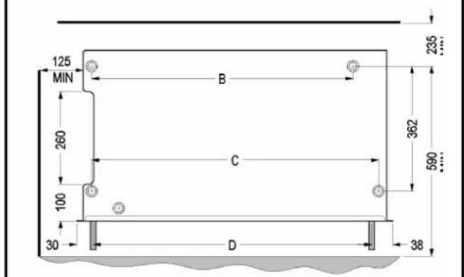
| A B C D | ||||
| SRX 080 | 503 | 324 | 396 | 386 |
| SRX 120 | 670 | 492 | 564 | 564 |
| SRX 140 | 740 | 562 | 634 | 624 |
| SRX 180 | 911 | 732 | 804 | 794 |

6


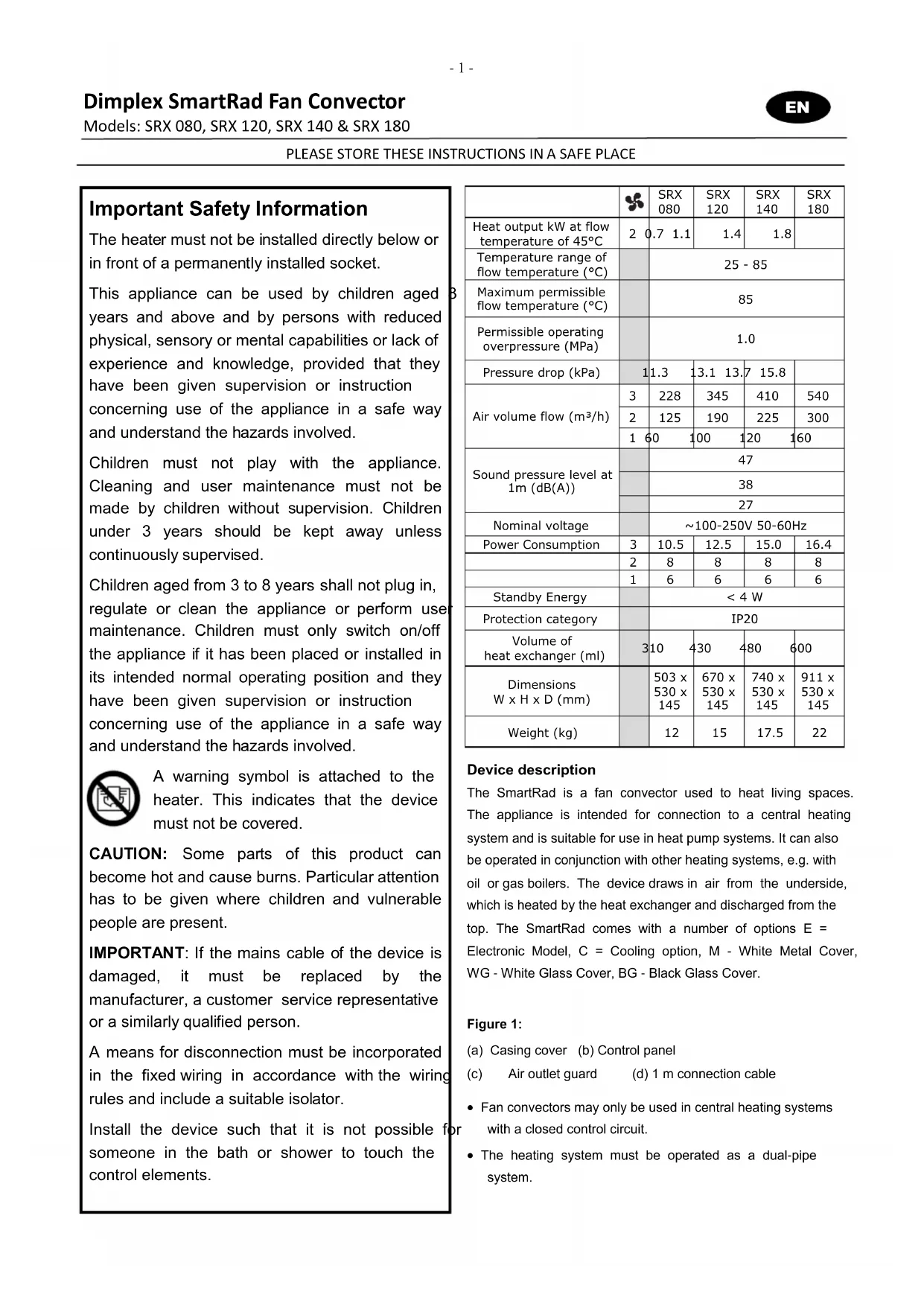
The heater must not be installed directly below or in front of a permanently installed socket.
This appliance can be used by children aged years and above and by persons with reduced physical, sensory or mental capabilities or lack of experience and knowledge, provided that they have been given supervision or instruction concerning use of the appliance in a safe way and understand the hazards involved.
Children must not play with the appliance. Cleaning and user maintenance must not be made by children without supervision. Children under 3 years should be kept away unless continuously supervised.
Children aged from 3 to 8 years shall not plug in, regulate or clean the appliance or perform use maintenance. Children must only switch on/off the appliance if it has been placed or installed in its intended normal operating position and they have been given supervision or instruction concerning use of the appliance in a safe way and understand the hazards involved.
A warning symbol is attached to the heater. This indicates that the device must not be covered.
CAUTION: Some parts of this product can become hot and cause burns. Particular attention has to be given where children and vulnerable people are present.
IMPORTANT: If the mains cable of the device is damaged, it must be replaced by the manufacturer, a customer service representative or a similarly qualified person.
A means for disconnection must be incorporated in the fixed wiring in accordance with the wiring rules and include a suitable isolator.
Install the device such that it is not possible for someone in the bath or shower to touch the control elements.
| 3 | SRX 080 | SRX 120 | SRX 140 | SRX 180 | |
| Heat output kW at flow temperature of 45°C | 2 | 0.7 1.1 | 1.4 | 1.8 | |
| Temperature range of flow temperature (°C) | 25 - 85 | ||||
| Maximum permissible flow temperature (°C) | 85 | ||||
| Permissible operating overpressure (MPa) | 1.0 | ||||
| Pressure drop (kPa) | 1 | 1.3 | 13.1 13.7 | 15.8 | |
| Air volume flow (m3/h) | 3 | 228 | 345 | 410 | 540 |
| 2 | 125 | 190 | 225 | 300 | |
| 1 | 60 | 100 | 120 | 160 | |
| Sound pressure level at 1m (dB(A)) | 47 | ||||
| 38 | |||||
| 27 | |||||
| Nominal voltage | ~100-250V 50-60Hz | ||||
| Power Consumption | 3 | 10.5 | 12.5 | 15.0 | 16.4 |
| 2 | 8 | 8 | 8 | 8 | |
| 1 | 6 | 6 | 6 | 6 | |
| Standby Energy | < 4 W | ||||
| Protection category | IP20 | ||||
| Volume of heat exchanger (ml) | 3 | 10 | 430 | 480 | 600 |
| Dimensions W x H x D (mm) | 503 x 530 x 145 | 670 x 530 x 145 | 740 x 530 x 145 | 911 x 530 x 145 | |
| Weight (kg) | 12 | 15 | 17.5 | 22 | |
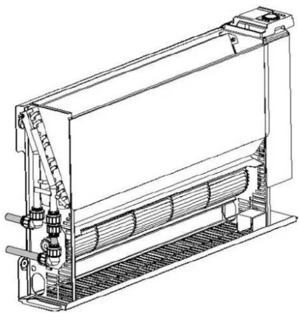
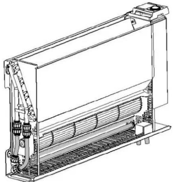
Device description
The SmartRad is a fan convector used to heat living spaces. The appliance is intended for connection to a central heating system and is suitable for use in heat pump systems. It can also be operated in conjunction with other heating systems, e.g. with oil or gas boilers. The device draws in air from the underside, which is heated by the heat exchanger and discharged from the top. The SmartRad comes with a number of options E = Electronic Model, C = Cooling option, M - White Metal Cover, WG - White Glass Cover, BG - Black Glass Cover.
Figure 1:
(a) Casing cover (b) Control panel
(c) Air outlet guard (d) 1 m connection cable
- Fan convectors may only be used in central heating systems with a closed control circuit.
-
The heating system must be operated as a dual-pipe system.
-
The devices must be of a sufficient rating to compensate for heat losses in the room.
Installation Notes
Combustible materials or liquids and other highly flammable furnishings must be kept away from the heater.
The heater must not be operated in very dusty areas.
Installation Preparation
- Remove packaging material.
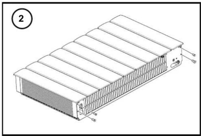
- Unscrew the four fixing screws from underside of device (see figure 2) to remove casing cover.
- Store the casing cover so that it cannot be damaged during installation.
Fixing to the wall
- For drywalls, use suitable fixing material (not supplied).
- Draw and drill four holes on a sturdy wall as shown in figure 5. All dimensions are in mm.
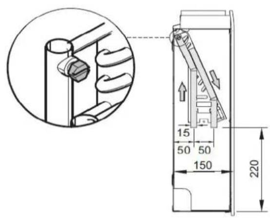
- Insert dowels and pre-fit the two top screws (don't completely screw in yet).
- Hang device on the two top screws.
- Insert and tighten the two bottom screws, then tighten the two top screws.
Hydraulic connection
To ensure a sufficient heating water flow rate through the fan convectors, please observe the following points:
- The devices are not suitable for installation in a single-pipe system.
- The nominal width of the connection pipe must have a minimum inner diameter of 15mm .
- If the devices are installed in a heating system with various heat distribution systems (e.g. under floor heating), a separate circuit is required to guarantee a sufficient water flow rate.
For optimum operation (heat output) of the fan convectors, a hydraulic balance is required on the heating system. Figure 6 shows the various hydraulic connection options on the device.
The recommended flow and return connections are shown in figure 5
The heating pipes can be laid in the floor or in the wall. The device is supplied with two copper pipes with a diameter of 15mm that are fitted on the heat exchanger at the factory.
Before and during filling of the heating system, all pipe connections must be checked for leaks. During filling, the bleeder valve (see figure 5) must be opened so that air can
escape from the device. If necessary, bleed again following commissioning (circulating pump running).
Electrical connection
WARNING: The device must be grounded
WARNING: Phase conductor (brown) and neutral conductor (blue) must not be swapped as this may cause malfunctions.
The electrical connection should have a supply voltage of 110 - 240V , 50 - 60Hz .
The device must be installed by a qualified electrician in compliance with the existing standards and local installation guidelines.
Before performing installation, ensure that the power supply is switched off.
The device is equipped with a flexible 1 m connection cable (4 × 0.75 mm^2) , which can be used to connect the heater directly to the power supply via a suitable wall socket. Disconnection must be incorporated in the fixed wiring in accordance with the wiring rules and include a suitable isolator. The isolator should have a contact opening width of at least 3mm on each pole and must provide full disconnection in overvoltage category III conditions.
Conductor configuration of the connection cable:
Brown: 'L' - supply voltage phase conductor
Blue: 'N' - supply voltage neutral conductor
Green/Yellow: 'PE' grounding conductor
Black: control conductor (temperature reduction; on/off)
For circuit diagram, see figure 8.
Pilot (Control) Wire
Activating the black pilot (control) wire allows you to lower the set target temperature on the device using an external timer or switch. Any reductions in temperature will be forwarded to downstream devices via the control wire. When a programming cassette is plugged into the master unit appliance and is operating, the control signals will also be forwarded to any downstream devices via the control wire. See figure 8 for more detail. When taking out of service, e.g. for maintenance work, ensure that both the mains supply and the control conductor are disconnected from the power supply, as this may result in external voltage (via a timer contact or pilot device with programming cassette).
WARNING: If you switch over to controlled operation, the mains voltage is on this conductor!
WARNING: Do not ground the control conductor
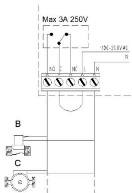
Connection to External Devices
The EC SmartRad can be connected to a number of external devices which can improve energy efficient operation. This is carried out by means of a relay on the PCB (see figure 7 for details). The basic function of the relay is when there is an energy demand, the relay will operate.
Connection to a building management system - the relay can be configured as a "volt free contact" which can be used to transmit a signal to a suitable control system (see figure 7 "A").
Connection to a pump / valve - the SmartRad can power an external pump and valve via its own supply. A standard solenoid valve or spring return valve (see figure 7 "B") or a standard circulation pump (see figure 7 "C") can be wired in as shown in figure 7 "B".
NO = Normally open and will operate the valve/pump.
N = Neutral for the valve/pump.
CAUTION - the valve and pump should be rated for the correct voltage.
CAUTION - the power requirement should not exceed 3 Amps at 250VAC.
Connection to a motorised valve - the SmartRad can switch on and switch off a standard motorised valve via its own supply.
NO = Normally open and will open the valve
NC = Normally closed and will close the valve
N = Neutral for the valve.
SmartRad Software Features
The EC SmartRad has a number of software features to aid the comfort and usability of the appliance. These different features can be accessed using the DIP switches found on the main PCB, and should be selected during installation of the appliance.
Bedroom Mode - for ultra quiet operation a lower set of motor speeds can be selected. This feature is very useful in low noise areas such as bedrooms.
Switch ON DIP switch number 1 for this feature. Note quiet operation reduces the performance of the SmartRad and therefore the appliance should be adequately sized for the room.
High Temperature Mode - for use with high temperature heat generators such as oil or gas boilers. In this mode the lower water temperature limit is increased to 45^ .
Switch on DIP switch number 2 for his feature.
Setback Mode - for use with pilot wire applications. In this mode, when a setback (reduced set point) signal is received, the SmartRad will reduce the set point on a sliding scale —
this will retain a certain amount of heat in the room. If this mode is off, a setback signal will revert to a "Frost Protection" mode. Normal comfort operation is not affected by this mode.
Operation Mode - Heating mode is only available on this appliance - DIP switch 4 should always be off.
Relay Mode - in this mode the relay is activated in accordance with the operating conditions.
Switch on DIP switch number 6 for this feature.
Keylock Operation - this mode is useful for public areas such as schools or offices, and disables the controls on the
appliance. To activate press the button for more than 15
seconds, this will disable the , butto and the
thermostat knob. To reactivate the appliance press the button for more than 15 seconds.
Final Installation
Fit casing cover following completion of installation work. To do this, screw in the four fixing screws on the underside of the device, see figure 2.
Operation
The control panel is shown in figure 3.
The individual elements have the following meaning:
A-Operating mode button
B-On/off indicator
C - Manual mode indicator
D - Automatic mode indicator
E-Fan level button
F - Low fan level indicator
G - Medium fan level indicator
H-High fan level indicator
J-Thermostat setting wheel
K-Cover for programming cassette slot
Always ensure proper operation. The air inlet and outlet grilles must not be covered or blocked.
Manual operation
Press the button once or several times until the yellow indicator lights up.

Press the button once or several times to select the max desired fan level (fan speed). The set fan level is indicated by the red indicator (1, 2, 3).
Set the desired room temperature with the knob.
The set fan level is switched on and off depending on the room temperature.
Automatic mode (eco)
Press the button once or several times until the red eco indicator lights up.
Set the desired room temperature with the knob. Depending on the current room temperature and the target temperature set on the thermostat, the electronics calculate which of the three fan levels (fan speeds) to use.
The electronics select the required fan level depending on the difference between the current room temperature and the desired target temperature.
If necessary, the number of possible fan levels can be reduced. For instance, to limit the fan levels to a maximum of 2, press the button once or several times until the second indicator lights up.
Operation with a programming cassette or a timer can only take place in automatic mode (eco). If there is a control signal, and appliance has reached its set point, the green eco indicator lights up.
Fault indication
If the water temperature is too low, operation of the device is interrupted and the red indicator flashes.
In this case, check that the heating system and circulating pump are operating correctly.
For more information, please refer to the "Troubleshooting" chapter.
Operation with air/water heat pumps
When operating with an air/water heat pump, particularly when temperatures are low outside, the heat pump's buffer tank must be at a temperature of at least 14^ to ensure that the heat pump evaporator can defrost. You should therefore ensure that thawing has taken place if necessary before opening the valves to the heating circuit.
Troubleshooting
The following issues may result in the fan convector producing insufficient heat and possibly the red indicator flashes. Possible causes for this are;
Air trapped in heat exchanger — Disconnect device from power supply, remove casing and bleed heat exchanger. For position of bleeder screw, see figure 5.
Water temperature too low — Set flow temperature higher on heating system.
Insufficient water flow rate through device - Adjust flow rate (hydraulic balance). To do this, close thermostat valves on the other heaters
Dirt on heat exchanger — Clean heat exchanger, see "Maintenance" section
Cleaning outer surfaces
The heater must be switched off and cooled for cleaning. The surfaces of the heater can be cleaned by wiping with a soft, damp cloth and then dried. Do not use abrasive powder or furniture polish to clean as these may damage the surface. During installation of the appliance - a helpful tip is to use the plastic packaging and carton to cover the appliance after it is installed - this prevents any building materials such as plaster or paint entering the appliance during renovation work on the property.
Maintenance - to be performed by a specialist
Before performing maintenance work on the device, disconnect it from the power supply. Dust or lint that collects inside the heater must be removed at regular intervals. To do this, disconnect the device from the power supply, loosen the 4 fixing screws on the underside of the casing and carefully remove the casing cover. Remove dirt with a soft brush or a vacuum cleaner.
Build-up of air in the heat exchanger can be remedied by opening the bleeder valve (figure 5). An air filter is also available for fitting to the air inlet of the appliance, please contact Dimplex for more information.
The operating instructions belong to the device and must be stored in a safe place. In case of a change in ownership, the operating instructions should be passed on to the new owner.
Warranty
We offer a two-year warranty for this device in accordance with our warranty conditions.
United Kingdom Dimplex - a division of the GDC Group Millbrook House Phone +44 08456005111 Grange Drive, Hedge End Fax +44 01489773050 Southampton, Hants, SO30 2DF www.dimplex.co.uk
Republic of Ireland
Airport Road
Cloghran
Co.Dublin
Raccordement hydraulique
Fil pilot (commande)
N = Neutral for ventilen/pumpen.
N = N_oytral for ventilen / pumpen.
E-Knapp for viftenivá
F - Indikator for lav't vifteniva
G - Indikator for middels vifteniva
H-Indikator for hootvifteniva
J-Termostatinnstillingshjul
K - Deksel for programmedskassetsporet
1599 Moss Fax.74829101
www.glendimplex.no
Glen Dimplex Nordic
Havnegata 24 TIf.74829100
7500 STJORDAL Fax. 74 82 91 01
www.glendimplex.no
N = Neutral for ventilen/pumpen.