
HWS 88180 Professional - Sander BOSCH - Free user manual and instructions
Find the device manual for free HWS 88180 Professional BOSCH in PDF.
| Product Type | Angle Grinder / Polisher |
| Brand | Bosch |
| Model | HWS 88180 Professional |
| Main Applications | Grinding, cutting, sanding, polishing, brushing |
| Power Supply | High-frequency three-phase via frequency converter |
| Rated Voltage | 400 V (three-phase) |
| Frequency | 300 Hz |
| No-Load Speed (approx.) | 8500 rpm |
| Max. Disc Diameter | 125 mm |
| Spindle Thread | M14 |
| Weight (approx.) | 2.5 kg |
| Sound Pressure Level | 82 dB(A) |
| Vibration Level (grinding) | 5 m/s² (uncertainty K=2 m/s²) |
| Protection Class | Double insulation (class II) |
| Overload Protection | Motor protection switch recommended |
| Additional Handle | Anti-vibration, mountable left or right |
| Protection Guard | For grinding and cutting (coded mounting) |
| Hand Guard | Mandatory for sanding and brushing |
| Dust Extraction | Possible with suitable accessory (stone cutting) |
| Maintenance | Clean ventilation slots regularly |
| Safety | Safety switch, restart prevented after power cut |
| Repairability | Original Bosch parts, repair by authorized service center |
Frequently Asked Questions - HWS 88180 Professional BOSCH
User questions about HWS 88180 Professional BOSCH
0 question about this device. Answer the ones you know or ask your own.
Ask a new question about this device
Download the instructions for your Sander in PDF format for free! Find your manual HWS 88180 Professional - BOSCH and take your electronic device back in hand. On this page are published all the documents necessary for the use of your device. HWS 88180 Professional by BOSCH.
USER MANUAL HWS 88180 Professional BOSCH
BUCH-2487-002. book Page 1 Wednesday, November 2, 2016 4:43 PM
HWS
06023014.060230440.060230540.06023064340602324..
06023295..|06023315..|06023325..|06023345..

BOSCH
on Original instructions
fr Notice originate
esManualoriginal
pt Manual original
ro instruction original
bgOpamHanHaHHepyKuB
mkOpmmnntynnrteoasa pabora
sr Original no uputative zaraed
Leimna narodila
br Original up
etAlugainr
Instituclias originala
Original Instukcia
n
1
- [12] [13] [14] [15]


Robert Bosch Power Tools GmbH
70538StuIgU
GERMANY
www.bosch-pt.com
160992A36G(2015.07)AS/473 EURO

1609 92A 36G
by Evemf haso 1asit is
2
nOpHAnBHe pykoBocrno
2018年1月16日
中
OBI_BUCH-2487-002.book Page 16 Wednesday, November 2, 2016 4:43 PM
16 | Deutsch
Executive Vice President
Head of Product Certification
Engineering
PT/ECS
f( 2) = h · d
Robert Bosch Power Tools GmbH
70538 Stuttgart,GERMANY
Stuttgart, 01.01.2017
Montage
OBI_BUCH-2487-002.book Page 17 Wednesday, November 2, 2016 4:43 PM
Deutsch 17
OBI_BUCH-2487-002.book Page 18 Wednesday, November 2, 2016 4:43 PM
18 | Deutsch
OBI_BUCH-2487-002.book Page 20 Wednesday, November 2, 2016 4:43 PM
20 | Deutschland
General Power Tool SafetyWarnings
WARNING Read all safety warnings and all instruc-tions. Failure to follow the warnings and instructions may result in electric shock, fire and/or serious injury.
Save all warnings and instructions for future reference. The term "power tool" in the warnings refers to your main-operated (corded) power tool or battery-operated (cordless power tool.
Work area safety
- Keep work area clean and well lit. Cluttered or dark areas invite accidents.
Do not operate power tools in explosive atmospheres, such as in the presence of flammable liquids, gases or dust. Power tools create sparks which may ignite the dust or fumes. - Keep children and bystanders away while operating a power tool. Distractions can cause you to lose control.
Electrical safety
Power tool plugs must match the outlet. Never modify the plug in any way. Do not use any adapter plugs with earthed (grounded) power tools. Unmodified plugs and matching outlets will reduce risk of electric shock.
- Avoid body contact with earthed or grounded surfaces, such as pipes, radiators, ranges and refrigerators. There is an increased risk of electric shock if your body is earthed or grounded.
Do not expose power tools to rain or wet conditions. Water entering a power tool will increase the risk of electric shock.
Do not abuse the cord. Never use the cord for carrying, pulling or unplugging the power tool. Keep cord away from heat, oil, sharp edges and moving parts. Damaged or entangled cords increase the risk of electric shock.
- When operating a power tool outdoors, use an extension cord suitable for outdoor use. Use of a cord suitable for outdoor use reduces the risk of electric shock.
If operating a power tool in a damp location is unavoidable, use a residual current device (RCD) protected supply. Use of an RCD reduces the risk of electric shock.
Personal safety
Stay alert, watch what you are doing and use common sense when operating a power tool. Do not use a power tool while you are tired or under the influence of drugs, alcohol or medication. A moment of inattention while operating power tools may result in serious personal injury.
Use personal protective equipment. Always wear eye protection. Protective equipment such as dust mask, non-skid safety shoes, hard hat, or hearing protection used for appropriate conditions will reduce personal injuries.
Prevent unintentional starting. Ensure the switch is in the off-position before connecting to power source and/or battery pack, picking up or carrying the tool. Carrying power tools with your finger on the switch or energising power tools that have the switch on invites accidents.
Remove any adjusting key or wrench before turning the power tool on. A wrench or a key left attached to a rotating part of the power tool may result in personal injury.
Do not overreach. Keep proper footing and balance at all times. This enables better control of the power tool in unexpected situations.
Dress properly. Do not wear loose clothing or jewellery. Keep your hair, clothing and gloves away from moving parts. Loose clothes, jewellery or long hair can be caught in moving parts.
If devices are provided for the connection of dust extraction and collection facilities, ensure these are connected and properly used. Use of dust collection can reduce dust-related hazards.
Power tool use and care
Do not force the power tool. Use the correct power tool for your application. The correct power tool will do the job better and safer at the rate for which it was designed.
Do not use the power tool if the switch does not turn it on and off. Any power tool that cannot be controlled with the switch is dangerous and must be repaired.
- Disconnect the plug from the power source and/or the battery pack from the power tool before making any adjustments, changing accessories, or storing power tools. Such preventive safety measures reduce the risk of starting the power tool accidentally.
Store idle power tools out of the reach of children and do not allow persons unfamiliar with the power tool or these instructions to operate the power tool. Power tools are dangerous in the hands of untrained users.
Maintain power tools. Check for misalignment or binding of moving parts, breakage of parts and any other condition that may affect the power tool's operation. If damaged, have the power tool repaired before use. Many accidents are caused by poorly maintained power tools.


OBI_BUCH-2487-002.book Page 23 Wednesday, November 2, 2016 4:43 PM
English|23
- Keep cutting tools sharp and clean. Properly maintained cutting tools with sharp cutting edges are less likely to bind and are easier to control.
- Use the power tool, accessories and tool bits etc. in accordance with these instructions, taking into account the working conditions and the work to be performed. Use of the power tool for operations different from those intended could result in a hazardous situation.
Service
Have your power tool serviced by a qualified repair person using only identical replacement parts. This will ensure that the safety of the power tool is maintained.
SafetyWarnings for AngleGrinder
Safety warnings common for sanding with sanding discs and polishing
Applies for the following types:
-06023014..
-060230540
-0602306434
-060232440
This power tool is to be used as a sander and polisher. Observe all safety warnings, instructions, illustrations and data supplied with the power tool. Non-observation of the following instructions can lead to electric shock, fire and/or serious injury.
Operations such as grinding, wire brushing or cutting off are not recommended to be performed with this power tool. Operations for which the power tool was not designed may create a hazard and cause personal injury.
Safety warnings common for grinding, working with wire brushes and cut-off grinding
Applies for the following types:
-060230440
-060232444,..464,..474,..434
-06023295..
-06023315..
-06023325.
-06023345..
This power tool is to be used as a grinder, wire brush and cut off grinder. Observe all safety warnings, instructions, illustrations and data supplied with the power tool. Non-observation of the following instructions can lead to electric shock, fire and/or serious injury.
Operations such as sanding or polishing are not recommended to be performed with this power tool. Operations for which the power tool was not designed may create a hazard and cause personal injury.
Safety warnings that are common for grinding, sanding, wire brushing, polishing and abrasive cutting off operations
Applies for all types
- Do not use accessories which are not specifically designed and recommended by the tool manufacturer. Just because the accessory can be attached to your power tool, it does not assure safe operation.
The rated speed of the accessory must be at least equal to the maximum speed marked on the power tool. Accessories running faster than their rated speed can break and fly apart.
The outside diameter and the thickness of your accessory must be within the capacity rating of your power tool. Incorrectly sized accessories cannot be adequately guarded or controlled.
- Threaded mounting of accessories must match the grinder spindle thread. For accessories mounted by flanges, the armour hole of the accessory must fit the locating diameter of the flange. Accessories that do not match the mounting hardware of the power tool will run out of balance, vibrate excessively and may cause loss of control.
Do not use a damaged accessory. Before each use inspect the accessory such as abrasive wheels for chips and cracks, backing pad for cracks, tear or excess wear, wire brush for loose or cracked wires. If power tool or accessory is dropped, inspect for damage or install an undamaged accessory. After inspecting and installing an accessory, position yourself and bystanders away from the plane of the rotating accessory and run the power tool at maximum no-load speed for one minute. Damaged accessories will normally break apart during this test time.
Wear personal protective equipment. Depending on application, use face shield, safety goggles or safety glasses. As appropriate, wear dust mask, hearing protectors, gloves and shop apron capable of stopping small abrasive or workpiece fragments. The eye protection must be capable of stopping flying debris generated by various operations. The dust mask or respirator must be capable of filtrating particles generated by your operation. Prolonged exposure to high intensity noise may cause hearing loss.
- Keep bystanders a safe distance away from work area. Anyone entering the work area must wear personal protective equipment. Fragments of workpiece or of a broken accessory may fly away and cause injury beyond immediate area of operation.
Hold the power tool by insulated gripping surfaces only, when performing an operation where the cutting accessory may contact hidden wiring or its own cord. Cutting accessory contacting a "live" wire may make exposed metal parts of the power tool "live" and could give the operator an electric shock.
Position the cord clear of the spinning accessory. If you lose control, the cord may be cut or snagged and your hand or arm may be pulled into the spinning wheel.
- Never lay the power tool down until the accessory has come to a complete stop. The spinning wheel may grab the surface and pull the power tool out of your control.
- Do not run the power tool while carrying it at your side. Accidental contact with the spinning accessory could snag your clothing, pulling the accessory into your body.
Bosch Power Tools 1609 92A 36C (2.11.16)


24|English
Regularly clean the power tool's air vents. The motor's fan will draw the dust inside the housing and excessive accumulation of powdered metal may cause electrical hazards.
Do not operate the power tool near flammable materials. Sparks could ignite these materials.
Do not use accessories that require liquid coolants. Using water or other liquid coolants may result in electrocution or shock.
Kickback and related warnings
Kickback is a sudden reaction to a pinched or snagged rotating wheel, backing pad, brush or any other accessory. Pinching or snagging causes rapid stalling of the rotating accessory which in turn causes the uncontrolled power tool to be forced in the direction opposite of the accessory's rotation at the point of the binding. For example, if an abrasive wheel is snagged or pinched by the workpiece, the edge of the wheel that is entering into the pinch point can dig into the surface of the material causing the wheel to climb out or kick out. The wheel may either jump toward or away from the operator, depending on direction of the wheel's movement at the point of pinching. Abrasive wheels may also break under these conditions.
Kickback is the result of power tool misuse and/or incorrect operating procedures or conditions and can be avoided by taking proper precautions as given below.
- Maintain a firm grip on the power tool and position your body and arm to allow you to resist kickback forces. Always use auxiliary handle, if provided, for maximum control over kickback or torque reaction during start-up. The operator can control torque reactions or kickback forces, if proper precautions are taken.
Never place your hand near the rotating accessory. Accessory may kickback over your hand.
Do not position your body in the area where power tool will move if kickback occurs. Kickback will propel the tool in direction opposite to the wheel's movement at the point of snagging.
- Use special care when working corners, sharp edges, etc. Avoid bouncing and snagging the accessory. Corners, sharp edges or bouncing have a tendency to snag the rotating accessory and cause loss of control or kickback.
Do not attach a saw chain woodcarving blade or toothed saw blade. Such blades create frequent kickback and loss of control.
Safety warnings specific for Grinding and Abrasive Cutting-Off operations
- Use only wheel types that are recommended for your power tool and the specific guard designed for the selected wheel. Wheels for which the power tool was not designed cannot be adequately guarded and are unsafe.
The grinding surface of the centre depressed wheels must be mounted below the plane of the guard lip. An improperly mounted wheel that projects through the plane of the guard lip cannot be adequately protected.
The guard must be securely attached to the power tool and positioned for maximum safety, so the least amount of wheel is exposed towards the operator. The guard helps to protect operator from broken wheel fragments, accidental contact with wheel and sparks that could ignite clothing.
Wheels must be used only for recommended applications. For example: do not grind with the side of the cut-off wheel. Abrasive cut-off wheels are intended for peripheral grinding; side forces applied to these wheels may cause them to shatter.
Always use undamaged wheel flanges that are of correct size and shape for your selected wheel. Proper wheel flanges support the wheel thus reducing the possibility of wheel breakage. Flanges for cut off wheels may be different from grinding wheel flanges.
Do not use worn down reinforced wheels from larger power tools. Wheels intended for larger power tools are not suitable for the higher speed of a smaller tool and may burst.
Additional safety warnings specific for abrasive cutting off operations
Do not "jam" the cut-off wheel or apply excessive pressure. Do not attempt to make an excessive depth of cut. Overstressing the wheel increases the loading and susceptibility to twisting or binding of the wheel in the cut and the possibility of kickback or wheel breakage.
Do not position your body in line with and behind the rotating wheel. When the wheel, at the point of operation, is moving away from your body, the possible kickback may propel the spinning wheel and the power tool directly at you.
When wheel is binding or when interrupting a cut for any reason, switch off the power tool and hold the power tool motionless until the wheel comes to a complete stop. Never attempt to remove the cut-off wheel from the cut while the wheel is in motion otherwise kickback may occur. Investigate and take corrective action to eliminate the cause of wheel binding.
Do not restart the cutting operation in the workpiece. Let the wheel reach full speed and carefully re-enter the cut. The wheel may bind, walk up or kickback if the power tool is restarted in the workpiece.
Support panels or any oversized workpiece to minimize the risk of wheel pinching and kickback. Large workpieces tend to sag under their own weight. Supports must be placed under the workpiece near the line of cut and near the edge of the workpiece on both sides of the wheel.
Use extra caution when making a "pocket cut" into existing walls or other blind areas. The protruding wheel may cut gas or water pipes, electrical wiring or objects that can cause kickback.
Safety warnings specific for sanding operations
Do not use excessively oversized sanding disc paper. Follow manufacturers recommendations, when selecting sanding paper. Larger sanding paper extending be


English | 25
yond the sanding pad presents a laceration hazard and may cause snagging, tearing of the disc, or kickback.
Safety warnings specific for polishing operations
Do not allow any loose portion of the polishing bonnet or its attachment strings to spin freely. Tuck away or trim any loose attachment strings. Loose and spinning attachment strings can entangle your fingers or snag on the workpiece.
Safety warnings specific for wire brushing operations
Be aware that wire bristles are thrown by the brush even during ordinary operation. Do not overstress the wires by applying excessive load to the brush. The wire bristles can easily penetrate light clothing and/or skin.
If the use of a guard is recommended for wire brushing, do not allow any interference of the wire wheel or brush with the guard. Wire wheel or brush may expand in diameter due to work load and centrifugal forces.
Additional safety warnings
Wear safety goggles.

ronment where special protection for persons is necessary. The special protection of persons is required, for example, when working in damp rooms or with materials that can produce current-conducting dust. Not using a residual current protection device can lead to electrical shock, risk of fire, or serious injuries.
The residual current protection device should be installed in the power supply network only by a qualified electrician. Only in this manner can proper functioning be ensured.
The output voltage and frequency of the frequency converter must correspond with the data on the type plate of the high-frequency tool.
- Operate the power tool exclusively with a fitting plug. The CEE plug must be dimensioned for the nominal current that the power tool requires (see "Technical Data").
Plug mounting and connection to the power supply is to be carried out by a qualified electrician trained in handling high-frequency tool systems.
Use only original cables! Before each use, check the power tool, cable and plug for possible damage. Cables and plugs may not be repaired, but must be exchanged in order to avoid danger.
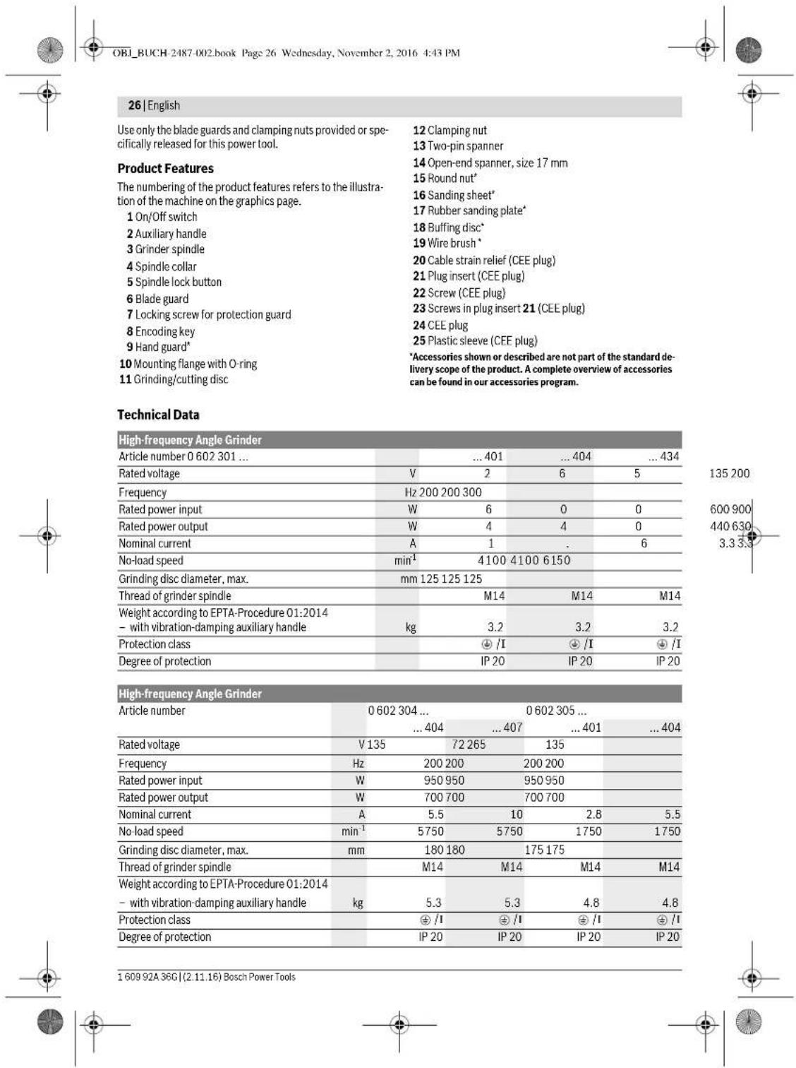
Product Description and Specifications

Read all safety warnings and all instructions. Failure to follow the warnings and instructions may result in electric shock, fire and/or serious injury.
While reading the operating instructions, unfold the graphics page for the machine and leave it open.
Intended Use
Applies for the following types:
-06023014..
-060230540.
-0602306434
-060232440.
The machine is intended for sanding and polishing metal and coated surfaces without the use of water.
Applies for the following types:
-060230440
-060232444,..464,..474,..434
-06023295.
-06023315..
-06023325..
-06023345
The machine is intended for cutting, roughing and brushing of metal and stone materials without the use of water.
For cutting with bonded abrasives, a special cutting guide (accessory) must be used.
When cutting in stone, provide for sufficient dust extraction.
Applies for all types
Use suitable detectors to determine if utility lines are hidden in the work area or call the local utility company for assistance. Contact with electric lines can lead to fire and electric shock. Damaging a gas line can lead to explosion. Penetrating a water line causes property damage or may cause an electric shock.
Release the On/Off switch and set it to the off position when the power supply is interrupted, e.g., in case of a power failure or when the mains plug is pulled. This prevents uncontrolled restarting.
Do not touch grinding and cutting discs before they have cooled down. The discs can become very hot while working.
When working with the machine, always hold it firmly with both hands and provide for a secure stance. The power tool is guided more securely with both hands.
Secure the workpiece. A workpiece clamped with clamping devices or in a vice is held more secure than by hand.
- Connect the machine to a mains supply with proper earthing connection. Socket outlet and extension cable must be equipped with an operative protective conductor.
Products sold in AUS and NZ only: Use a residual current device (RCD) with a rated residual current of 30mA or less.
SafetyWarnings for the Power Supply of Highfrequency Tools
The safety warnings and working instructions of the frequency converter are to be strictly observed! For detailed information, contact the manufacturer of the frequency converter.
The frequency converter must be secured with a residual current protection device when working in an envi


OBI_BUCH-2487-002.book Page 29 Wednesday, November 2, 2016 4:43 PM
English | 29
Notes on the Power Supply
The power tool is part of a high-frequency system and requires three-phase current with a frequency according to the type plate.
To reach this frequency, the power tool must be connected with a frequency converter (see "Connection to the Power Supply", page 33).
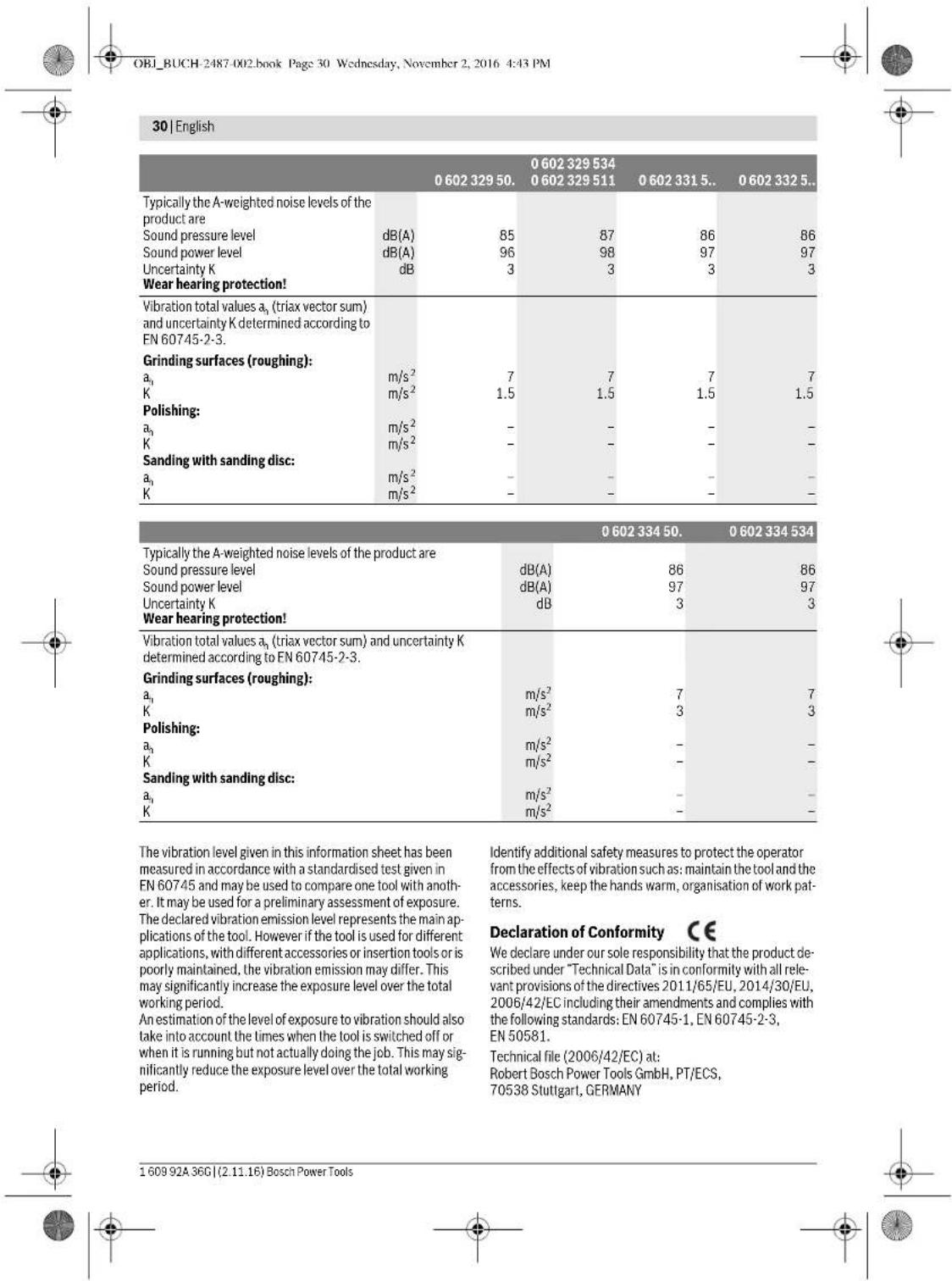
Noise/Vibration Information
Sound emission values determined according to EN 60745-2-3.
| 0 602 301 40. | 0 602 301 434 | 0 602 304 40. | 0 602 305 40. | |
| Typically the A-weighted noise levels of the product are | ||||
| Sound pressure level | dB(A) | 72 | 82 | 79 |
| Sound power level | dB(A) | 83 | 93 | 90 |
| Uncertainty K | dB | 3 | 3 | 3 |
| Wear hearing protection! | ||||
| Vibration total values \( a_{\mathrm {n}} \)(triax vector sum) and uncertainty K determined according to EN 60745-2-3. | ||||
| Grinding surfaces (roughing): | ||||
| \( a_{\mathrm {n}} \) | m/s2 | - | 5.3 | 5 |
| K | m/s2 | - | 2 | 2 |
| Polishing: | ||||
| \( a_{\mathrm {n}} \) | m/s2 | 3 | 3 | - |
| K | m/s2 | 1.5 | 1.5 | - |
| Sanding with sanding disc: | ||||
| \( a_{\mathrm {n}} \) | m/s2 | 3 | 3 | - |
| K | m/s2 | 1.5 | 1.5 | - |
| 0 602 306 434 | 0 602 324 40. | 0 602 324 44,0 602 324 4640 602 324 4740 602 324 434 | |
| Typically the A-weighted noise levels of the product are | |||
| Sound pressure level dB(A) | 82 | 77 | 82 |
| Sound power level dB(A) | 93 | 88 | 93 |
| Uncertainty K dB | 3 | 3 | 3 |
| Wear hearing protection! | |||
| Vibration total values \( a_h \) (triax vector sum) and un-certainty K determined according to EN 60745-2-3. | |||
| Grinding surfaces (roughing): | |||
| \( a_h \)m/s2 | - | - | 6 |
| Km/s2 | - | - | 2 |
| Polishing: | |||
| \( a_h \)m/s2 | < 2.5 | 4 | - |
| Km/s2 | 1.5 | 1.5 | - |
| Sanding with sanding disc: | |||
| \( a_h \)m/s2 | < 2.5 | 4 | - |
| Km/s2 | 1.5 | 1.5 | - |
Bosch Power Tools 1609 92A 36C (2.11.16)
English | 31
Henk Becker
Executive Vice President Engineering
Heimut Heinzelmann
Head of Product Certification PT/ECS

iV. k = m
Robert Bosch Power Tools GmbH
70538 Stuttgart,GERMANY
Stuttgart, 01.01.2017
Assembly
Mounting the Protective Devices
General Information
- Disconnect the power supply before making any adjustments, changing accessories, or placing the machine aside. This safety measure prevents accidental starting of the power tool.
Note: After breakage of the grinding disc during operation or damage to the holding fixtures on the protection guard/power tool, the machine must promptly be sent to an after-sales service agent for maintenance. For addresses, see section "After-sales Service and Application Service".
Adjust protection guards in such a manner that sparking toward the operator is prevented.
Note: The encoding keys of the protection guards ensure that only a protection guard that fits the machine type can be mounted.
Protection Guard for Grinding (see figure A)
Applies for the following types:
-060230440. -06023295..
-0602324434 -06023315..
-060232444. -06023325..
-0602324464 -06023345.
-0602324474
- Place the protection guard 6 with the encoding key 8 engaging into the groove on the spindle collar 4 until the shoulder of the protection guard is seated against the flange of the power tool.
- Adapt the position of the protection guard to the requirements of the work step.
- Secure the protection guard by tightening locking screw 7 with a tightening torque of at least 10Nm .
Protection Guard for Cutting
Applies for the following types:
-060230440. -06023295..
-0602324434 -06023315..
-060232444. -06023325..
-0602324464 -06023345..
-0602324474
For cutting with bonded abrasives, always use a protection guard for cutting.
For cutting stone, always use a cutting guide with dust extraction protection guard (accessory).
The protection guards for cutting are mounted analogue to the standard protection guards (see figure A).
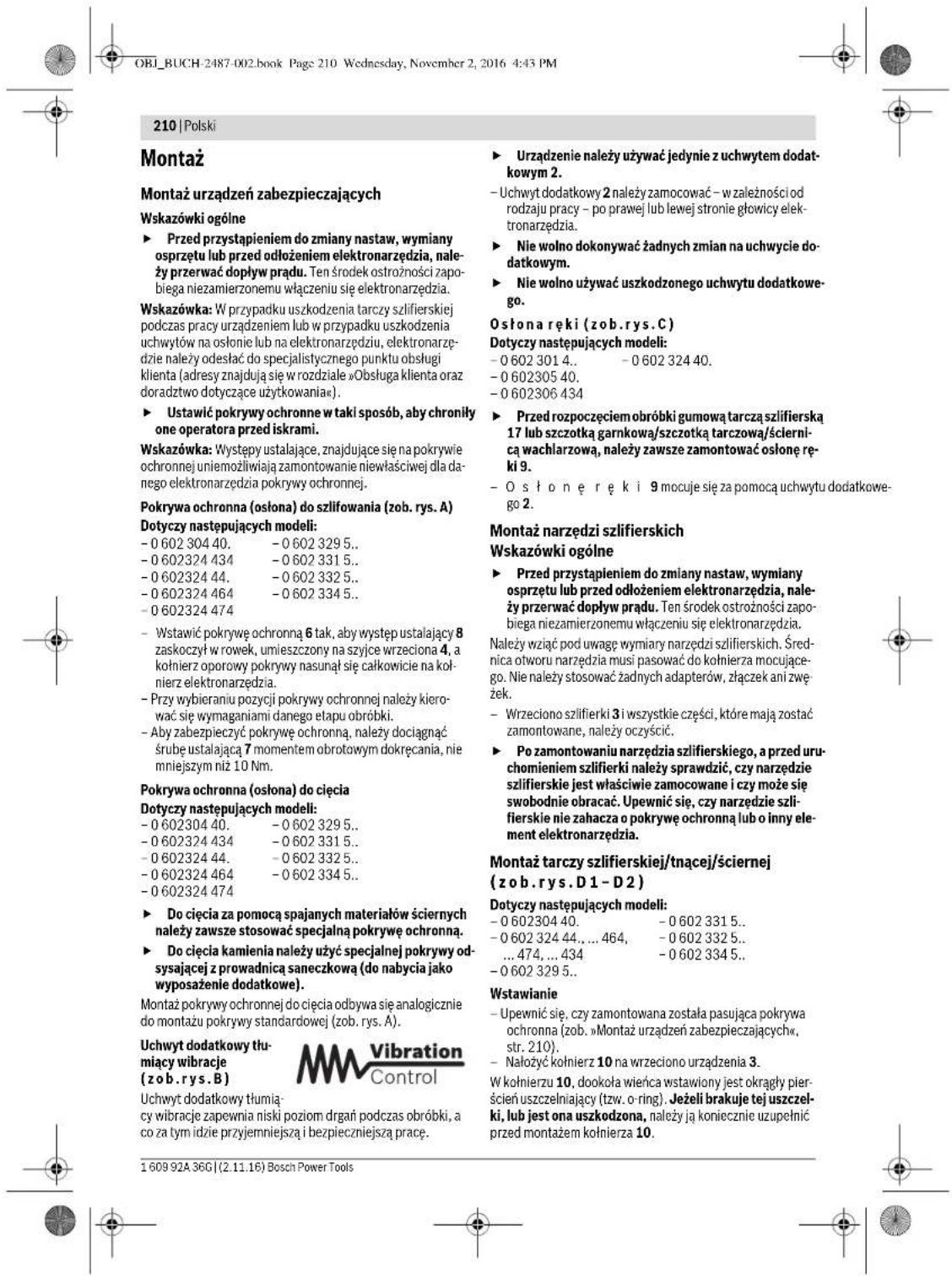
Vibration-dampening
Auxiliary Handle
(see figure B)
The vibration-dampening auxiliary handle reduces the vibrations, making operation more comfortable and secure.
Operate your machine only with the auxiliary handle 2.
- Screw the auxiliary handle 2 on the right or left of the machine head depending on the working method.
Do not make any alterations to the auxiliary handle.
Do not continue to use an auxiliary handle if it is damaged.
Hand Guard (see figure C)
Applies for the following types:
-06023014.. -060232440.
-060230540.
-0602306434
For operations with the rubber sanding plate 17 or with the cup brush/wheel brush/flap disc, always mount the hand guard 9.
The hand guard 9 is fastened with the auxiliary handle 2.
Mounting the Grinding Tools
General Information
Disconnect the power supply before making any adjustments, changing accessories, or placing the machine aside. This safety measure prevents accidental starting of the power tool.
Pay attention to the dimensions of the grinding tools. The mounting hole diameter must fit the mounting flange without play. Do not use reducers or adapters.
Clean the grinder spindle 3 and all parts to be mounted.
After mounting the grinding tool and before switching on, check that the grinding tool is correctly mounted and that it can turn freely. Make sure that the grinding tool does not graze against the protection guard or other parts.
Mounting Grinding or Cutting Discs (see figures D1-D2)
Applies for the following types:
-060230440. -06023315..
-060232444,..464 -06023325.
474.434 -06023345..
-06023295..
Installation
- Make sure that the fitting protection guard is mounted (see "Mounting the Protective Devices", page 31).
- Place the clamping flange 10 on the grinder spindle 3. A plastic part (O ring) is fitted around the centring collar of mounting flange 10. If the O-ring is missing or damaged, it must immediately be replaced before mounting flange 10 is mounted.
- Mount the desired grinding/cutting disc 11 in the correct rotation direction onto the grinder spindle 3.


OBI_BUCH-2487-002.book Page 32 Wednesday, November 2, 2016 4:43 PM
32|English
- Place the clamping nut 12 onto the spindle thread so that the central recess of the clamping nut faces upward.
Tighten the clamping nut with two-pin spanner 13, while counter-holding the spanner surfaces of the grinder spindle 3 with open-end spanner 14.
Removal
Hold the grinder spindle 3 on the spanner surfaces with open-end spanner 14.
- Unscrew the clamping nut 12 from the grinder spindle with two-pin spanner 13, while counter-holding the spanner surfaces with open-end spanner 14.
- Afterwards, pull the grinding tool and the mounting flange from the grinder spindle.
Machines with Spindle Lock Button 5
Applies for the following types:
-060232440.
-0602324434
-060232444.
For machines with spindle lock button 5, counter-holding with an open-end spanner is not required when mounting grinding tools (see figures E1-E2).
- Actuate the spindle lock button only when the grinder spindle is at a standstill. Otherwise, the machine may become damaged.
- Before installing or removing the grinding tool, press and hold spindle lock button 5 to lock the grinder spindle 3 in place.
- Mount the desired grinding tool (see "Mounting Grinding or Cutting Disks", page 31).
- Let go of the spindle lock button 5 to release the locked grinder spindle.
Mounting the Rubber Sanding Plate (see figure F)
Applies for the following types:
-06023014. -060232440
-060230540.
-0602306434
Installation
-
Make sure that the hand guard and the auxiliary handle are mounted (see "Mounting the Protective Devices", page 31).
-
Place the rubber sanding plate 17 onto the grinder spindle 3.
-Lay the sanding disc 16 on the rubber sanding plate. - Place the round nut 15 on the spindle collar.
- Tighten the round nut with two pin spanner 13, while counter-holding the spanner surfaces of the grinder spindle 3 with open-end spanner 14.
Take care that the round nut 15 is screwed completely into the bulge of the rubber sanding plate so that it does not interfere while sanding and the sanding disc is firmly seated.
Removal
Hold the grinder spindle 3 on the spanner surfaces with open-end spanner 14.
- Unscrew the round nut 15 from the grinder spindle with two-pin spanner 13, while counter-holding the spanner surfaces with open-end spanner 14.
- Pull the sanding disc and the rubber sanding plate from the grinder spindle.
Mounting the Buffing Disc (see figure G)
Applies for the following types:
Pay attention that the thread of the buffing disc fits exactly on the grinder spindle thread (M14).
Make sure that the hand guard and the auxiliary handle are mounted (see "Mounting the Protective Devices", page 31).
- Screw the buffing disc 18 so far onto the grinder spindle 3 that it rests firmly against the face surface of the grinder spindle, while counter-holding the spanner surfaces of the grinder spindle 3 with open-end spanner 14.
Removal
Unscrew the tightly seated buffing disc 18 from the grinder spindle by applying an open-end spanner to the buffing disc spanner surfaces, while counter-holding the spanner surfaces of the grinder spindle 3 with open-end spanner 14.
Mounting Wire Brushes (see figure H)
Applies for the following types:
-060230440. -06023315..
-060232444,..464, -06023325.
474.434 -06023345..
-06023295..
Installation
Pay attention that the thread of the wire brush fits exactly on the grinder spindle thread (M14).
Make sure that the hand guard and the auxiliary handle are mounted (see "Mounting the Protective Devices", page 31).
Screw the desired wire brush 19 (cup brush or wire wheel) so far onto the grinder spindle 3 that it rests firmly against the face surface of the grinder spindle, while counter-holding the spanner surfaces of the grinder spindle with open-end spanner 14.
Removal
- Unscrew the tightly seated wire brush 19 from the grinder spindle by applying an open-end spanner to wire brush spanner surfaces, while counter-holding the spanner surfaces of the grinder spindle 3 with open-end spanner 14.
Dust/Chip Extraction
Dusts from materials such as lead-containing coatings, some wood types, minerals and metal can be harmful to one's health. Touching or breathing-in the dusts can cause allergic reactions and/or lead to respiratory infections of the user or bystanders.
1609 92A 36G| (2.11.16) Bosch Power Tools


English | 33
Certain dusts, such as oak or beech dust, are considered as carcinogenic, especially in connection with wood-treatment additives (chromate, wood preservative). Materials containing asbestos may only be worked by specialists.
- As far as possible, use a dust extraction system suitable for the material.
- Provide for good ventilation of the working place.
- It is recommended to wear a P2 filter-class respirator. Observe the relevant regulations in your country for the materials to be worked.
Prevent dust accumulation at the workplace. Dusts can easily ignite.
Connection to the Power Supply
For operation of the power tools, a frequency converter is required that generates three-phase current with a frequency according to that listed on the type plate.
Frequency converters are available in various sizes, with different frequencies, secondary voltages and rated outputs. The choice of the frequency converter depends on the power tools to be connected. When selecting a frequency converter, contact your Bosch-specialist shop for advice.
The machine is provided with a four meter long specialty cable without plug. To put it into operation, the specialty cable must be equipped with a four-pole CEE plug (identification colour green).
Additionally, the machine can be equipped with a commercially available motor protection switch for protection against overload. The adjustment range of the motor protection switch must cover the nominal current of the power tool (see "Technical Data"). The motor protection switch must react in less than one second.
Please observe the safety warnings and assembly instructions in the operating instructions of the motor protection switch!
Mounting the CEE Plug (see figures 11-12)
- Loosen the two screws 22 and pull the plug insert 21 out of the plug housing of the CEE plug 24.
Cut off the plastic sleeve 25 according to the diameter of the specialty cable of the power tool and insert the specialty cable through the CEE plug housing. - Insert the four conductors through the cable strain relief 20.
- Loosen the four small screws 23 in the plug insert 21 and insert
the conductor ferrule of the brown L1 conductor into contact tube L1,
the conductor ferrule of the blue L2 conductor into contact tube L2,
the conductor ferrule of the black L.3 conductor into contact tube L3,
and the conductor ferrule of the green/yellow conductor into the earthing contact tube
- Firmly tighten the four small screws 23 in the plug insert 21 to affix the conductors.
-
Now, tighten the screws of the cable strain relief 20 so that the cable clamp goes around the complete cable sheath, ensuring that no pressure is on the conductor ferrules.
-
Reinsert plug insert 21 into the housing of the CEE plug 24 and tighten both screws 22 again.
- Afterwards, check the proper function of the protective conductor.
- Insert the CEE plug 24 of the power tool into the connection socket of the frequency converter.
Now, connect the frequency converter to the power supply. For information on how to connect the frequency converter to the power supply, see the frequency converter operating instructions.
Afterwards, check the rotation direction!
Checking the Rotation Direction
The rotation direction of the grinder spindle must correspond with the arrow on the power tool.
If the grinder spindle rotates in the wrong direction when putting into operation for the first time (see "Switching the Power Tool On/Off", page 34), switch the power tool off immediately and disconnect it from the power supply.
- Loosen the two screws 22 again and pull the plug insert 21 out of the plug housing of the CEE plug 24.
- Loosen the conductor ferrules of the black and brown conductors from their contact tubes.
- Now, insert the conductor ferrule of the black conductor L3 into contact tube L1, and the conductor ferrule of the brown conductor L1 into contact tube L3.
- Firmly tighten the small screws 23 in the plug insert 21 to affix the conductors.
- Reinsert plug insert 21 into the housing of the CEE plug 24 and tighten both screws 22 again.
- Afterwards, check the proper function of the protective conductor.
- Reconnect the power tool to the power supply.
Operation
Starting Operation
The voltage and frequency of the power source must correspond with the data on the type plate of the power tool.
- Check grinding tools before using. The grinding tool must be mounted properly and be able to move freely. Carry out a test run for at least one minute with no load. Do not use damaged, out-of-centre or vibrating grinding tools. Damaged grinding tools can burst and cause injuries.
If the machine should unexpectedly stop operating even though the On/Off switch 1 is in the "On" position, set the On/Off switch to "Off". This will prevent uncontrolled restarting of the machine. Before restarting the machine, check the power supply (see "Connection to the Power Supply", page 33).
Always connect the power tool to the frequency converter first, before connecting the frequency converter to the mains supply.
To save energy, only switch the power tool on when using it.


34|English
Switching the Frequency Converter On/Off
The frequency converter must be put into operation first before actuating the power tool.
For this, observe the operating instructions of the frequency converter.
Switching the Power Tool On/Off with the On/Off Switch (see figure J1)
Applies for the following types:
-06023244.
- To start the machine, push the On/Off switch 1 forwards.
- To lock the On/Off switch 1, press the On/Off switch 1.
down at the front until it latches.
To switch off the power tool, release the On/Off switch 1. When the On/Off switch 1 is locked-on, briefly press it toward the rear and then release it.
Switching the Power Tool On/Off
with Safety Switch (see figure J2)
Applies for the following types:
-06023014. -06023295.
-060230440. -06023315.
-060230540-06023325
-0.602306434 -0.6023345
- To start the power tool, press the On/Off switch 1 forward and then down.
- To lock on the pressed On/Off switch 1, push the On/Off switch 1 further forward.
- To switch off the power tool, release the On/Off switch 1.
or when it is locked, briefly press the On/Off switch 1 and then release it.
Working Advice
- Disconnect the power supply before making any adjustments, changing accessories, or placing the machine aside. This safety measure prevents accidental starting of the power tool.
Exercise caution when cutting slots in structural walls; see Section "Information on Structures".
Clamp the workpiece if it does not remain stationary due to its own weight.
Do not strain the machine so heavily that it comes to a standstill.
After heavily straining the power tool, continue to run it at no-load for several minutes to cool down the accessory.
Sanding with the Flap Disc
With the flap disc (accessory), curved surfaces and profiles can be worked.
Flap discs have a considerably higher service life, lower noise levels and lower sanding temperatures than conventional sanding sheets.
Cutting Metal (see figure K)
For cutting with bonded abrasives, always use a protection guard for cutting.
When cutting, work with moderate feed, adapted to the material being cut. Do not exert pressure onto the cutting disc, tilt or oscillate the machine.
Do not reduce the speed of running down cutting discs by applying sideward pressure.
The machine must always work in an up-grinding motion. Otherwise, the danger exists of it being pushed uncontrolled out of the cut.
When cutting profiles and square bar, it is best to start at the smallest cross section.
Cutting Stone
- Provide for sufficient dust extraction when cutting stone.
Wear a dust respirator.
The machine may be used only for dry cutting/grinding.
For cutting stone, it is best to use a diamond cutting disc. For safety against jamming, a special cutting guide with dust extraction protection guard (accessory) must be used.
Operate the machine only with dust extraction and additionally wear a dust protection mask.
The vacuum cleaner must be approved for the extraction of masonry dust. Bosch provides suitable vacuum cleaners.
- Switch on the machine and place the front part of the cutting guide on the workpiece. Slide the machine with moderate feed, adapted to the material to be worked.
For cutting especially hard material, e. g., concrete with high pebble content, the diamond cutting disc can overheat and become damaged as a result. This is clearly indicated by circular sparking, rotating with the diamond cutting disc.
In this case, interrupt the cutting process and allow the diamond cutting disc to cool by running the machine for a short time at maximum speed with no load.
Noticeably decreasing work progress and circular sparking are indications of a diamond cutting disc that has become dull. Briefly cutting into abrasive material (e.g., lime-sand brick) can reshappen the disc again.
Information on Structures
Slots in structural walls are subject to the Standard DIN 1053 Part 1, or country-specific regulations.
These regulations are to be observed under all circumstances. Before beginning work, consult the responsible structural engineer, architect or the construction supervisor.
Rough Grinding
Never use a cutting disc for roughing.
The best roughing results are achieved when setting the machine at an angle of 30° to 40° . Move the machine back and forth with moderate pressure. In this manner, the workpiece will not become too hot, does not discolour and no grooves are formed.
Sanding with Sanding Discs and the Rubber Sanding Plate
The choice of the suitable sanding paper depends on the material to be worked.
Bosch offers various sanding-paper qualities that fit the rubber sanding plate. Contact your specialist shop for advice.

OBI_BUCH-2487-002.book Page 35 Wednesday, November 2, 2016 4:43 PM
Polishing with the Buffing Disc
When polishing, a polishing agent is applied to the buffing disc or the material being polished, and worked into the surface of the material by means of rotation.
When working in several polishing steps, where each polishing agent has a finer grain, a separate buffing pad must be used for each grain size.
Thoroughly clean the surface of the material being worked between each polishing step.
Maintenance and Service
Maintenance and Cleaning
Disconnect the power supply before making any adjustments, changing accessories, or placing the machine aside. This safety measure prevents accidental starting of the power tool.
For safe and proper working, always keep the machine and ventilation slots clean.
In extreme conditions, always use dust extraction as far as possible. Blow out ventilation slots frequently and install a portable residual current device (PRCD). When working metals, conductive dust can settle in the interior of the power tool. The total insulation of the power tool can be impaired.
Regularly measure the no-load speed of the grinder spindle. When the measured value is more than 10% above or below the specified no-load speed (see "Technical Data"), have the machine checked by an authorised service agent for Bosch power tools. When the no-load speed is too high, the application tool can break; when the no-load speed is too low, the working performance is reduced.
Use only original cables! Before each use, check the power tool, cable and plug for possible damage. Cables and plugs may not be repaired, but must be exchanged in order to avoid danger.
Have maintenance and repair work performed only by qualified specialists. In this manner, it can be ensured that the safety of the power tool is maintained.
Clean the connection sockets, couplers and plugs of the tool, after it has been disconnected from the mains supply, using a dry, lint-free cloth and remove dust and dirt particles.
Clean the gearbox after the first 150 running hours using a mild solvent. Follow the solvent manufacturers directions for use and disposal. Lubricate the gearbox using Bosch gearbox lube. Repeat the lubrication procedure every 300 hours after the initial gearbox service.
An authorized Bosch after-sales service agent will carry out this work quickly and reliably.
If the replacement of the supply cord is necessary, this has to be done by Bosch or an authorized Bosch service agent in order to avoid a safety hazard.
Please store and handle the accessory(-ies) carefully.
English 35
Accessories
Information about the complete quality accessory program can be found on the Internet at www.bosch-pt.com and www.boschproductiontools.com or at your dealer.
After-sales Service and Application Service
Our after-sales service responds to your questions concerning maintenance and repair of your product as well as spare parts. Exploded views and information on spare parts can also be found under:
www.bosch-pt.com
Bosch's application service team will gladly answer questions concerning our products and their accessories.
In all correspondence and spare parts orders, please always include the 10-digit article number given on the nameplate of the product.
Great Britain
Robert Bosch Ltd. (B.S.C.)
P.O.Box 98
Broadwater Park
North Orbital Road
Denham
Uxbridge
UB95HJ
At www.bosch-pt.co.uk you can order spare parts or arrange the collection of a product in need of servicing or repair.
Tel. Service: (0344) 7360109
E-Mail: boschservicecentre@bosch.com
Ireland
OrigO Ltd
Unit 23 Magna Drive
Magna Business Park
City West
Dublin 24
Tel. Service: (01) 4666700
Fax: (01) 4666888
Australia, New Zealand and Pacific Islands
Robert Bosch Australia Pty. Ltd.
Power Tools
Locked Bag 66
Clayton South VIC 3169
Customer Contact Center
Inside Australia:
Phone: (01300) 307044
Fax: (01300) 307045
Inside New Zealand
Phone: (0800) 543353
Fax: (0800) 428570
Outside AU and NZ:
Phone:+61395415555
www.bosch.com.au
Republic of South Africa
Customer service
Hotline: (011) 6519600


OBI_BUCH-2487-002.book Page 36 Wednesday, November 2, 2016 4:43 PM
36 | Français
Gauteng - BSC Service Centre
35 Roper Street, New Centre
Johannesburg
Tel.: (011) 4939375
Fax: (011) 4930126
E-Mail: bsctools@icon.co.za
KZN - BSC Service Centre
Unit E, Almar Centre
143 Crompton Street
Pinetown
Tel.: (031) 7012120
Fax: (031) 7012446
E-Mail: bsc.dur@za.bosch.com
Western Cape - BSC Service Centre
Democracy Way, Prosperity Park
Milnerton
Tel.: (021) 5512577
Fax: (021) 5513223
L-Mail: bsc@zsd.co.z
Bosch Headquarters
Midrand, Gauteng
Tel.: (011) 6519600
Fax: (011) 6519880
E-Mail: rbsa-hq.pts@za.bosch.com
Disposal
The machine, accessories and packaging should be sorted for environmental-friendly recycling.
Do not dispose of power tools into household waste!
Only for EC countries:
According to the European Directive 2012/19/EU for Waste Electrical and Electronic Equipment and its implementation into national right, power tools that are no longer usable must be collected separately and disposed of in an environmentally correct manner.
Subject to change without notice.
Français
OBI_BUCH-2487-002.book Page:45 Wednesday, November 2, 2016 4:43 PM
Francais | 45
OBI_BUCH-2487-002.book Page:46 Wednesday, November 2, 2016 4:43 PM
46 | Français
Executive Vice President
Engineering
Helmut Heinzelmann
Head of Product Certification
PT/ECS

iV. h = mc
Robert Bosch Power Tools GmbH
70538 Stuttgart,GERMANY
Stuttgart, 01.01.2017
Montage
OBI_BUCH-2487-002.book Page:61 Wednesday,November 2,2016 4:43PM
Henk Becker Helmut Heinzelmann Executive Vice President Head of Product Cert Engineering PT/ECS

Robert Bosch Power Tools GmbH
70538 Stuttgart,GERMANY
Stuttgart, 01.01.2017
Montaje
OBI_BUCH-2487-002.book Page 62 Wednesday, November 2, 2016 4:43 PM
62 | Espanol
4hastra estarcellearcadaperuza protectora contra la brida de la herramanta electrica.
OBI_BUCH-2487-002.book Page:63 Wednesday,November 2,2016 4:43 PM
Espanol|63
OBI_BUCH-2487-002.book Page:65 Wednesday,November 2,2016 4:43PM
Espanol|65
-06023014. 06023295..
-060230440. -06023315..
-060230540. -06023325..
-0602306434 -06023345..
OBI_BUCH-2487-002.book Page 75 Wednesday, November 2, 2016 4:43 PM
Portugues 75
OBI_BUCH-2487-002.book Page 76 Wednesday, November 2, 2016 4:43 PM
76 | Português
Executive Vice President
Engineering
Helmut Heinzelmann
Head of Product Certification

Robert Bosch Power Tools GmbH
70538 Stuttgart,GERMANY
Stuttgart, 01.01.2017
Montagem
OBI_BUCH-2487-002.book Page: 85 Wednesday, November 2, 2016 4:43 PM
Italiano|85
OBI_BUCH-2487-002.book Page:91 Wednesday,November 2,2016 4:43PM
Italiano|91
OBI_BUCH-2487-002.book Page:93 Wednesday, November 2, 2016 4:43 PM
Executive Vice President
Engineering
Helmut Heinzelmann
Head of Product Certification
PT/ECS

i.v. k = m _____
Robert Bosch Power Tools GmbH
70538 Stuttgart,GERMANY
Stlglart,01.01.2017
Bosch Power Tools 1609 92A 36C (2.11.16)


94 Italiano
Montaggio
OBI_BUCH-2487-002.book Page 97 Wednesday, November 2, 2016 4:43 PM
Italiano 97
OBI_BUCH-2487-002.book Page 104 Wednesday, November 2, 2016 4:43 PM
104 Nedenlands
OBI_BUCH-2487-002.book Page 107 Wednesday, November 2, 2016 4:43 PM
Nederlands | 107
OBI_BUCH-2487-002.book Page 109 Wednesday, November 2, 2016 4:43 PM
Nederlands|109
Henk Becker Helmut Heinzelmann Executive Vice President Head of Product Certification Engineering PT/ECS

Robert Bosch Power Tools GmbH 70538 Stuttgart,GERMANY Stuttgart,01.01.2017
Montage
OBI_BUCH-2487-002.book Page 110 Wednesday, November 2, 2016 4:43 PM
110|Nedenlnds
OBI_BUCH-2487-002.book Page 123 Wednesday, November 2, 2016 4:43 PM
Dansk|123
| 0 602 329 50. | 0 602 329 534 | 0 602 331 5.. | 0 602 332 5.. | ||
| 0 602 329 511 | |||||
| Samléde vibrationsværddier \( a_h \) (vektorsumfor tre retninger) og usikkerhed K beregnetiht. EN 60745-2-3. | |||||
| Overfladeslibning (skrubning): | |||||
| \( a_h \) | \( m/s^2 \) | 7 | 7 | 7 | 7 |
| K | \( m/s^2 \) | 1,5 | 1,5 | 1,5 | 1,5 |
| Polering: | |||||
| \( a_h \) | \( m/s^2 \) | - | - | - | - |
| K | \( m/s^2 \) | - | - | - | - |
| Slibning med silbeblad: | |||||
| \( a_h \) | \( m/s^2 \) | - | - | - | - |
| K | \( m/s^2 \) | - | - | - | - |
| 0 602 334 50. | 0 602 334 534 | |
| Værktajets A-vurdere lydtrykniveau er typisk | ||
| Lydtrykniveau | dB(A) | 86 |
| Lydeffektniveau | dB(A) | 97 |
| Usikkerhed K | dB | 3 |
| Brug horevaarn! | ||
| Samlke vibrationsværddier \( a_{i} \) (vektorsum for tre retninger) ogusikkerhed K beregnet iht. EN 60745-2-3. | ||
| Overfladeslibning (skrubning): | ||
| \( a_{i} \) | \( m/s^2 \) | 7 |
| K | \( m/s^2 \) | 3 |
| Polering: | ||
| \( a_{i} \) | \( m/s^2 \) | - |
| K | \( m/s^2 \) | - |
| Slibning med silbeblad: | ||
| \( a_{i} \) | \( m/s^2 \) | - |
| K | \( m/s^2 \) | - |
Det syingningsniveau, der er angivet i nervaerende instruk tioner, er blevet malt ith. en standardiseret malprocesi
Executive Vice President
Engineering
Helmut Heinzelmann
Head of Product Certification
PT/ECS

Robert Bosch Power Tools GmbH
70538 Stuttgart,GERMANY
Stuttgart, 01.01.2017
Montering
OBI_BUCH-2487-002.book Page 132 Wednesday, November 2, 2016 4:43 PM
132 | Svenska
-060232444,464.474.434
-06023295..
-06023315..
-06023325
-06023345..
OBI_BUCH-2487-002.book Page 135 Wednesday, November 2, 2016 4:43 PM

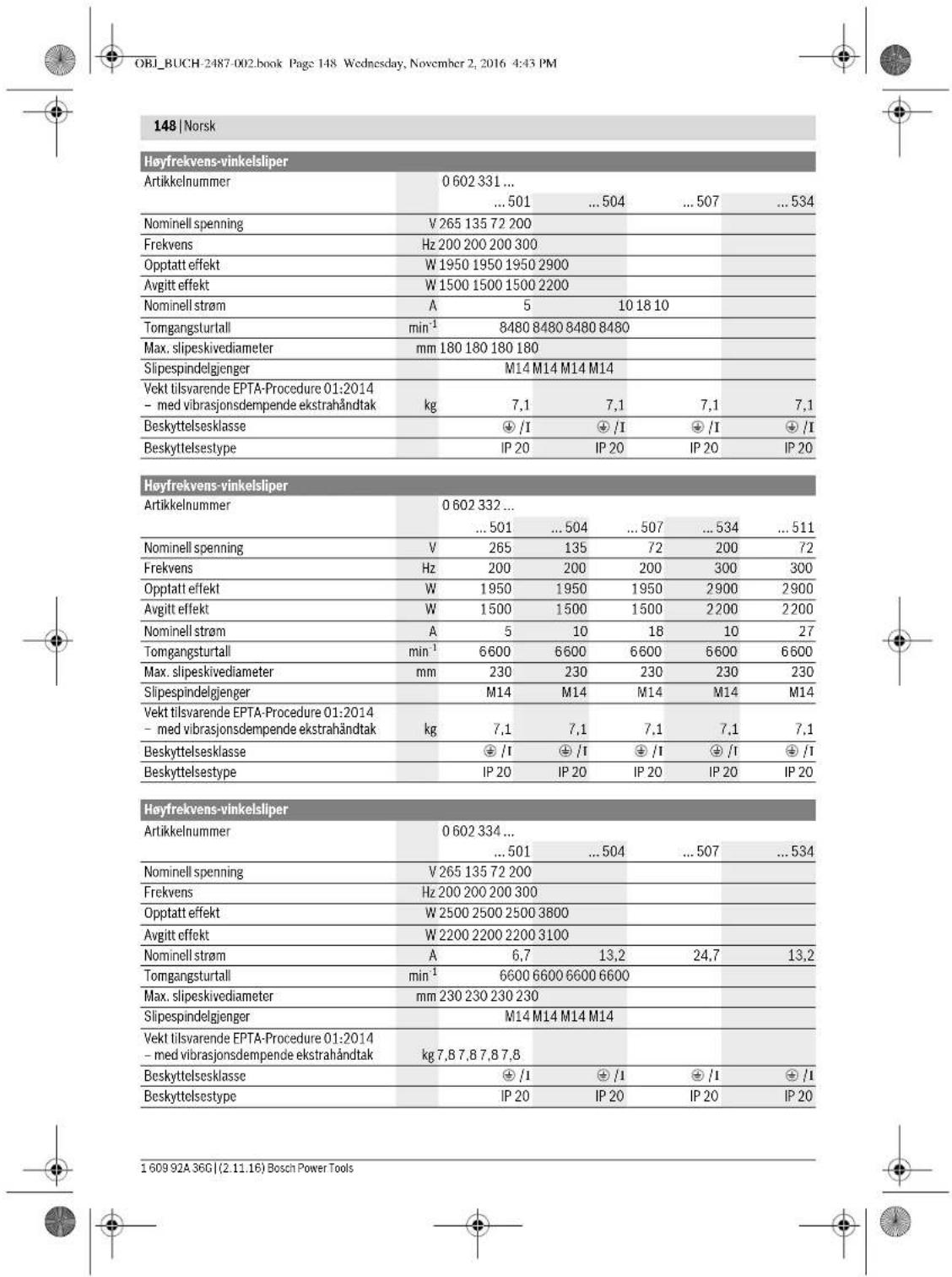
| Högtfrekvensvinkelslipar | ||||||
| Märkström A | 5 | 10 18 10 27 | ||||
| Tomgängsvarvalt | min1 | 6600 | 6600 | 6600 | 6600 | |
| max. slipskivsdiameter | mm 230 | 230 | 230 | 230 | ||
| Slipspindelgänga | M14 | M14 | M14 | M14 | ||
| Vikt enligt EPTA-Procedure 01:2014 | - med vibrationsdämpande stöchhandtag | kg | 7,1 | 7,1 | 7,1 | 7,1 |
| Skyddsklass | ± /I | ± /I | ± /I | ± /I | ||
| Kapslingsklass | IP 20 | IP 20 | IP 20 | IP 20 | ||
| Högfrektvensvinkelslipar | |||||
| Artikelnummer | 0 602 334 ... | ||||
| ... 501 | ... 504 | ... 507 | ... 534 | ||
| Märksprüning | V | 265 | 135 | 72 | 200 |
| Frekvens | Hz | 200 | 200 | 200 | 300 |
| Upptagen märkeffekt | W | 2500 | 2500 | 2500 | 3800 |
| Avgiven märkeffekt | W | 2200 | 2200 | 2200 | 3100 |
| Märkström | A | 6,7 | 13,2 | 24,7 | 13,2 |
| Tomgangsvarval | min¹ | 6600 | 6600 | 6600 | 6600 |
| max. slipskivsdiameter | mm | 230 | 230 | 230 | 230 |
| Slippspindelgänga | M14 | M14 | M14 | M14 | |
| Vikt enligt EPTA-Procedure 01:2014 - med vibrationsdämpande stödhandtag | kg | 7,8 | 7,8 | 7,8 | 7,8 |
| Skyddsklass | #/1 | #/1 | #/1 | #/1 | |
| Kapslingsklass | IP 20 | IP 20 | IP 20 | IP 20 | |
OBI_BUCH-2487-002.book Page 137 Wednesday, November 2, 2016 4:43 PM


Henk Becker
Executive Vice President Engineering
Helmut Heinzelmann
Head of Product Certification
PT/ECS

∴ V.H = WC
Robert Bosch Power Tools GmbH
70538 Stuttgart, GERMANY
Stuttgart, 01.01.2017
Montage
OBI_BUCH-2487-002.book Page 138 Wednesday, November 2, 2016 4:43 PM
138 | Svenska
Vibrationsdampande stodhantag (sebild B)
OBI_BUCH-2487-002.book Page 140 Wednesday, November 2, 2016 4:43 PM
140 | Svenska
Bosch Service Center
Telegrafvej 3
2750 Ballerup
Danmark
Tel.: (08) 7501820 (inom Sverige)
Fax: (011) 187691
Avfallshantering
Gjelder for all type


OBI_BUCH-2487-002.book Page 149 Wednesday, November 2, 2016 4:43 PM
Norsk|149
Rett tilendringer forbeholds.
Suomi
Turvallisuusohjeita
OBI_BUCH-2487-002.book Page 159 Wednesday, November 2, 2016 4:43 PM
Suomi | 159
OBI_BUCH-2487-002.book Page 163 Wednesday, November 2, 2016 4:43 PM
Suomi | 163
| 0602 301 40. | 0602 301 434 | 0602 304 40. | 0602 305 40. | |
| Värähtely nhteisarvot a, (kolmen suunnan vektorisumma) ja epävarnuus K mitattuna EN 60745-2-3 mukaan. | ||||
| Pintahionta (karhennus): | ||||
| a, | m/s2 | - | 5,3 | 5 |
| K | m/s2 | - | 2 | 2 |
| Kiillotus: | ||||
| a, | m/s2 | 3 | 3 | - |
| K | m/s2 | 1,5 | 1,5 | - |
| Honta hiomapaperilla: | ||||
| a, | m/s2 | 3 | 3 | - |
| K | m/s2 | 1,5 | 1,5 | - |
OBI_BUCH-2487-002.book Page 164 Wednesday, November 2, 2016 4:43 PM
164 | Suomi
Henk Becker
Executive Vice President Engineering
Helmut Heinzelmann
Head of Product Certification
PT/ECS

iV. k = m _____
Asennus
OBI_BUCH-2487-002.book Page 165 Wednesday, November 2, 2016 4:43 PM
Suomi | 165
-060230440. -06023295..
-0602324434 -06023315..
-060232444. -06023325..
-0602324464 -06023345..
-0602324474
Iayei yia touc eHtumouc:
OBI_BUCH-2487-002.book Page 174 Wednesday, November 2, 2016 4:43 PM
174|EAAnvKa
Iepiypaipn Tou npoiovtroc kal nct loxuoTou

AiaBdote dAc Tc umoBeIeic aopaaelac kai Tc onybei, Aueaeie, KATA my thponr Tuv unOdeEaw oapalei Ka Tu oybnWu npoei va npokAAouov Nkckronlgy, npkayv h/kaonpaouc Taupaunpouoc.
Iapakaloupe avolte tn dumuovn eolba me tvneukovian Tnc ouokucu Ka ophiote tvnv aovn 0o0 ba diajbcet n obnyie xcpiaui.
XpnoofoovaeTOVnpoopto
Iayei yia touc Eeh tumouc
OBI_BUCH-2487-002.book Page 179 Wednesday, November 2, 2016 4:43 PM


Henk Becker Helmut Heinzelmann Executive Vice President Head of Product Certification Engineering PT/ECS
fωxIω 0 i.v. h · m
Robert Bosch Power Tools GmbH 70538 Stuttgart, GERMANY Stuttgart, 01.01.2017
SigmaoJyOn
EuvaopAoynonTw npOATEuTkw biataEew
Tevikec unobedi
Na anouuvdeTe Tn ouakeun ao Tny tropoodota niv bdeEpyete Kmaia 0puon, npnv ano3eTe To NkepKPO cyAio notav npoeirai va AAAeTe KAnoo EAptna. AuTo npOpaauKtiko MteTO eNIOIeTkyataAOBoc EKKIVON TOu NkEPKPO cyAeiou.
Ynei:Ee neipinwnnou kata ndiapkeia nTg epyaoc
onao o diokoc acicvanc no anouotuv BmBoi ot iataneic uno
doxohrto npovpukmaikpa/ota nKepkpo epyaole,TOte TO
nKekkoepo epyaalelo pmei va npokoojate/ano tanaol aqoe
OTo Service. Tia atcakentie dieuovoc bIe To Kepaalio
"Service ka npoxy ouubouw xphonca.
Na puHlEte Tou npauAukTpec KATe TEOIO ToPO,
Ote o OvNpApoc v nuV kateuovte noc toxip
Yn Taekvnta Kukidokoianyoc stou pnoiaakntpec eaoafoauov, ani mopoie vaovapaooygel ovoac katoL hao Lc y to ekatotare nAeKtropio evaepia nooepiaikpact.
Iipopukaktpa yia aeavon (beta ekova A) Ioybei yia touc Eehc tumouc:
-060230440. -06023295..
-0602324434 -06023315..
-060232444. -06023325..
-0602324464 -06023345..
-0602324474
TOnoBteIOTOVnpOaKTHpa6TeToekkVToKwDkoI OJNC80toNaQdKwDkoIoinCtoAouTOaOVA4


OBI_BUCH-2487-002.book Page 180 Wednesday, November 2, 2016 4:43 PM
180|EAAnuKa
mexviXaKIOcIe nepAuaIou npOoaknpaNnOtn
pAoiVtU NauKETIKOU OyaekIo.
Iayet yia tou c efnc rounoc:
-06023014.. -060232440.
-060230540.
-0602306434
TonoBttn
-BeBaiuOeIe,OnEiaauapAooynOeIO npopuaKtnpacXepWn knpoetmAoJIb (BIAEe 2VUAPPOyonTuv npo starcutkouv bdoekovc,oclaHf.
TonoBTeTToAaOnxEvIOdiKocIeAoVcN 17nvoOToV oEoAoVAcN.3
Tonoetnto too kao aeIavoc 16 nva o ra aonvEvio 60kao aeIavoc.
TonotheTto Tpoyyu naia 15 0to oneipua Tou eOva.
Biswate kaka to otpovuolo naqabi me yavntokkeio 13, evo tauotpoova Kovipadepe te yocayvko 14 otny emapoeia eapaooyou tou keiouot ov deova leiavanoc 3. PoooEtic, va biobei to atopovuolo naqabi 15 cvtacwcu ovo any cooxn tou laanovoi biaokou leiavanc, via va uny cunodikei neov katin keiavan kai va npaaopupcctarat afoepa to pfAIOLeiavanc.
Anopukvov
-Kaonrtoe oeroeo roevoklaevoc 3no emepvda eaoovc no kieoi meu vovukke Kieoi 14.
-3e6oare to atoyuyu noauiy 10 me yavickei3o 13 am to ov afova laevanoc, evu turoxpova kovtpapete me to yepauvuk Keaiol 14nnr eioeiae apayopoyu tue Ksiouei.
- Aepaipatre To puaAe laivong, kai To maTiyevio diAko laivanc and tov dAoe laivanc.
Suvapoloyan tou slakou otiaawon (Bnae ekoVaG)
IoyuTuia Touc Eehr tonouc:
OBI_BUCH-2487-002.book Page 183 Wednesday, November 2, 2016 4:43 PM
EAMyikα183
UvOeTe nOtro npTo nAektpko cpyaleo pe To metatponea ouoxvtntc, npTo uovoocteto metatponea ouoxvtntc oTo kSttuTo tou pOuToc.
Na Etete To nAekpkrpoepaelyo aeLeauymo ydo Ate npok Keiia To yponpaonoiote. Eto Ekoovokolenevpeia.
Evpyonoinan/ancvpcyonoin Tou pctarponed ouxovnttac
Pnnpa va geoetoe to petatponeaouyovntac oe kiouogya, npotra va umopetre ve evpyonoyoepote to nkektpiok epeiaelo.
IIpoeEte y' auto n c obnyle c aeitoupyiac tou metarponema au xyvntan.
OeTou nAekptokoucpaIcIOueAIEtoupyia KKTcO Aieuopoye me auopoye biakonnt aopaaIacL (BNE eikova J1)
Iaxei yia touc eEHC tumouc:
-06023244
- Via σ eoctoe acetourpia To aekrpoik oepaiao wheore to biakemn ON/OFF 1 npoc to eumoo.
- Ia va paavbaaocre to diaokom ON/OFF 1 marnrto 6kakomON/OF 1 mmpoora, mexvi va paavbaaoc.
Tn anepepononou nKpOcypAoe npo
Me gnoonpoynoe to dokkOnn On/Off 1 nathne
guytoa nic npoc ta katw kal ghotote toy mete e 0ep.
Oeou n aeekpokoeyakoc aeitoupyka kctoc Aetouyia
μe biakomtn aopaaelac (βhene eikova J2)
Iayueya rouc eEhctunouc:
-06023014.. -06023295..
-060230440. -06023315..
-060230540. -06023325..
-0602306434 -06023345..
- Tia va theoc oc lectovya ra Iekpkiop cyalAcio wthotc to diaokom ON/OFF 1 npoc ra eipoc kai akolouuucnntne ToV.
Tia va pavbaaote tv natmuve biaknttn ON/OFF 1
Wto ta biaknttn ON/OFF 1 akou npaooepo npoc ta
eipoc
Ia va 0eTc kTocpia ngkckpckpy aophate to diakomn ON/OFF 1 eueoepj,av elva jnu6daawevoc, nathote ovvoTa o biakomn 1 kaakolouwoc apohate tvnelepeo.
Ynobsieicepyaiae
Na anouovbete Tn oukeun ao nTv npofoola npv
biEiyede Kanaiao pOoiu, npv anoTeTo nAekpiko
epaio I oTav npokeira va aAeEte Kanoio EAptn
uau To npovaiaktoe metro eumoiie Tny kato AooB
ekkivno TOn aNkptkoq evaeiaei.
Ptooohn oan bieokoyote oxaece poevoctoixouc, Bane Kepaiaio UynoielEue yin tnaT.
Na apiyetye to uno katepyala tepaio drav 6e aabe- ponoetra aapaaoc an to loio tou ro apoc.
Mnycipabocve nnaekpokcpayaleo 00n oao Oeae va aqatmoei va kivetai.
Mera ano ma nauHa emapauan tou cypaleloi va to qyvette vce cyetca yeaepuaenr kaojwn xwpic qoioyva ykpuoe to tonoctnvoe cyaeiao.
Aeavon me to do kO Aeavonc me qullapakia
Me to piooeoie biokaoiacevong (cuiokoo eaojirua) uipoeite va katoeayote kaiuueae imgeueae ki kaiotoue.
Osi diaokoeic biokoi Ieavanc exou via onuavnka peyauotep ndiakoeia Cwchxunntepn otogun BopouBau kai xunntotepeoepkoapaeie,leavanc and Touc auipatkoic diakoue Ieavanc.
Konn petaaow (baene eikova K)
Kota tvn komee eepa mua o6epeu uukia Lelav-onv xa npnoioeirne nvtore evn noopuaKnptna.
Oraevpeoee me Touclokou konnc va okeite peta npo08nnon, npooapouoovn 0r cKaToTe u no KATEpyia uko. Na uny nieTcTe to lok oKOnc, va uny Tov loKeet e Ka va uny Tov TaAveTbe.
Mny nieTe Touc biokouk konnc ano Ta ndya yva Touc cta parnoe Tpyopotepa.
ToIeKrkia epAeAo ipeNei oBnElyiue foqO avNtEBnTnFpOc nepTPOPFO Tou kIOu. AipOpertkua npAeX KUVooc V naTeoiavcEeKekyra EeO ano tvnTou.
Otov kobe diatopoe (poia) Ka terpavuvkoc ouayaneva agxicr tnv konm on kipotcn diatopoi.
Konn nepwpatw
F TnTnv konetnpaov npeneva opovrtae yia jia enapok avappopn oKoVCN.
Φopate paoka npoataiaac an o kovn.
To aekpOcpoeiae eioe nepetai va xnpouonoeiato povo yia Enj haleyEnj knon.
Tn Tn Knn nepac xnaaionoe iK aLtepeva diaaviro kono KNTC. Ta Tn aoPdAe ano Tuov udykaia otny konm je nela oohaneipene va xnaaionoeiTa evac npouaknt Paeue avopopn.
*Otro evpyaedae me to nektokoepyaiaelo va yete mavotre ouvapuoloynoei tvn avappoanonokovnc ka v npopate emontc ka odoa npootoiaac an okovnc.
O anopooopnpiac ookovnc npenei va eivai katalknooc yia tvv aavoppoyn ookovnc netpuatuiu. H Bosch npoeapepei katalknlouc oanopooptne cokovnc.
-0eTeTo nAekpKO epyaleo ae leitoupykaaiakouumntote To me To npatoTNO pOec Tou oupoevou Ondyo enaVua 0to katepyaTejuxo. OBelote To nAekpKO epyaleo me eptia npowon, npocapuooen oTo umkatepyacl Ako
'Orav kocnt noAo oAnpa uAka,pi. y, mctov nou nepiecxnoAo axkki, unopel va unephepaevdei ka va unootei qua o diauata rothioac komc.Evacotepavooc omnogouou ou aumepioroepetai aia me to diapaurotoko konnc amorele i eupavn evdcenwauto.
ΣμiaTeTOna nepiTnua biokouy tny konH kαρθoτe to biapuviδkO KOHVA ncpiTpaepcya iya liyo xpvO xwpic oopio yva KpuKud.
Mia ouanvikia meiueyn npnoooc eoyaoalar kic evacnupne opeouopoc nceovagoc omniopoiog amoeaiov evb5iec yea


184|EAAnuKa
TnAaBauon Tou daanovkou Konnc, Mnopoecte va Tov topo- xieote nai dieyoyovac uovtoupec konc, c aeioetukuikia, n. x. oe aoeBstaoiho.
YnobelEeue ytn otatikn
Oi oxiopec epepoyrec toixouc unokiviato npotino DIN 1053 Mepoc 1 notouc aviatooxuc kavoviouoc nck cka- otrae xupac.
Oi dai aei acuii npene iiaipovta onoynotne. Tpv apy aetne my epya oac va uouBouaeote tov ueuvo yia tn atrauknayaukiov, tov axrckrova to fiecbuyuT ov Epyu.
Ecxovdpoua
Mn xpoaionouocte note diakouc komc y Eaovdpoia.
Me ywia npo0baIc 30e6c 40e imuivvveTe kato TExovbipia apota anoteleqotia.Kwite rto nAekptko epayakeo Ano kwioanekawvntac mepria pieon. EToT o uno katepeyia teaxia de BepaivetueuproBak, ev alaeXpOaK aE6 dnmuoyouvuaoaKaoc
Aeoyaeayaoepo ae aonrno Aelavn H eoyou kaoanou yaoaoprou eaparai ao to kto oono npncvi cneepyataei.
H Bosch npoepeci diapoepe noiotncc qukauv keiaovanc, ka-talnae yaaatnevo biokao keiaovanc. Znthe oubouAoc an tov auvtipooan oac
OBI_BUCH-2487-002.book Page 192 Wednesday, November 2, 2016 4:43 PM
192|Türke
| Yüksek frekansl taşlama makinesi | |||||
| Ürün kodu | 0 602 334 ... | ||||
| ... 501 | ... 504 | ... 507 | ... 534 | ||
| Anma gerilimi | V 265 135 72 200 | ||||
| Frekans | Hz 200 200 200 300 | ||||
| Girgis Güçü | W 2500 2500 2500 3800 | ||||
| Çkış Güçü | W 2200 2200 2200 3100 | ||||
| Anma akimi | A 6 | , | 7 | 13,2 24,7 13,2 | |
| Bostaki devirsaysı | dev/dak 6600 6600 6600 6600 | ||||
| Maks. taşlama disiki çapı | mm 230 230 230 230 | ||||
| Taşlama mili disi | M14 M14 M14 M14 | ||||
| Ağırkı EPTA-Procedure 01:2014'e gère - Titresjm onleyici ek tutamakla | kg 7,8 | 7,8 | 7,8 | 7,8 | |
| Korum sunifi | ®/I | ®/I | ®/I | ®/I | |
| Korum tişi | IP 20 | IP 20 | IP 20 | IP 20 | |
Enerji beslemesine iliskin aciklamalar
Elektriki el aleti yuksek frekansystemin bir parcasidir ve tip etiketinde belirtlen frekansa sahip 3 fazl alternatif akim gerektirir.
Bu krekansa ulasabilmek ici elektrikli el aletinin bir krekans donusturuciyede bagl olmasi gerekir (bakiniz: "Enerjiikmaline baglantri, saya 196).
OBI_BUCH-2487-002.book Page 193 Wednesday, November 2, 2016 4:43 PM
Turkce 193
| 0 602 306 434 | 0 602 324 40. | 0 602 324 44. | |
| 0 602 324 464 | |||
| 0 602 324 474 | |||
| 0 602 324 434 | |||
| Toplam titreşimiGeorge tergeleri a.(iççın)...ve tolerans K, EN 60745-2-3 uyarınca.Yüsey taşlama(kazıma): | |||
| a1m/s2- | - | - | 6 |
| Km/s2- | - | - | 2 |
| Polisaj: | |||
| a1m/s2<2.5 | 4 | - | |
| Km/s21.5 | 1.5 | 1.5 | - |
| Zimpara kalık ilezimpara: | |||
| a1m/s2<2.5 | 4 | - | |
| Km/s21.5 | 1.5 | 1.5 | - |
OBI_BUCH-2487-002.book Page 194 Wednesday, November 2, 2016 4:43 PM
194|Turkce
Belirtilien titresim seviyesi elektrikli el alotinin temel kullanim alanarini temsili eder. Anek acelektrilki el ati baska kullaanlari alanlarnda, farki aksesuarla, farki uzclarla kullaanlirken veya yeterisz bakluma kullanlirken, titresim seviyesi belirtilien degerden farkli obalibur. Da bu toplam calisma suresi icindeki titresim yukunin onemil ojcle arturilir.
Titresimi yukun lam okayatahmin ede bilmek icin aletin kapa- li oldugu vya calstigi halde kullanladigui surer die dikkate alnmaldir. Bu, toplam calisma suresi icindeki titresimi yukun Snemli ocidce azaltablir.
Titresimin kullanciya bindirigi yuk icin onceden ek guvenik onlemleri alini. Ornegin: Elektriki elaetinin ve oclarin bakimi, ellerin sicak tutulmasi, is asamalarinin organize edilmisi.
Uygunluk beyani
C
Henk Becker Helmut Heinzelmann Executive Vice President Head of Product Certification Engineering PT/ECS

iV. k = m _____
Robert Bosch Power Tools GmbH
70538 Stuttgart, GERMANY
Stuttgart, 01.01.2017
Montaj
OBI_BUCH-2487-002.book Page 203 Wednesday, November 2, 2016 4:43 PM
Polski 203
OBI_BUCH-2487-002.book Page 204 Wednesday, November 2, 2016 4:43 PM
204| Polski
OBI_BUCH-2487-002.book Page 207 Wednesday, November 2, 2016 4:43 PM
Polski 207
OBI_BUCH-2487-002.book Page 209 Wednesday, November 2, 2016 4:43 PM
Executive Vice President Engineering
Helmut Heinzelmann
Head of Product Certification PT/ECS

iV. k = m
Robert Bosch Power Tools GmbH
70538 Stuttgart, GERMANY
Stuttgart, 01.01.2017
Bosch Power Tools 1609 92A 36C (2.11.16)


OBI_BUCH-2487-002.book Page 211 Wednesday, November 2, 2016 4:43 PM
Polski 211
Robert Bosch Sp. zo.o.
OBI_BUCH-2487-002.book Page 219 Wednesday, November 2, 2016 4:43 PM
Cesky|219
trickym proudem, nebezpeci pozaru nebo vaznym zranenim.
OBI_BUCH-2487-002.book Page 223 Wednesday, November 2, 2016 4:43 PM
Cesky|223
OBI_BUCH-2487-002.book Page 224 Wednesday, November 2, 2016 4:43 PM
224|Cesky
Henk Becker Helmut Heinzelmann Executive Vice President Head of Product Certification Engineering PT/ECS

iV. k = m _____
Robert Bosch Power Tools GmbH
70538 Stuttgart, GERMANY
Stuttgart, 01.01.2017
Montáž
Deleni kovu (viz obr.K)
Pro ododelovani povom poci zavanzh brusnych prostrekku vzdy pouzivejte ochranny kryt pro deleni.
Pri deleni pracujte s mirmyn posuvm pizpusobenym ochcavananemu materialu. Na delici kotouc nepusobte zadnymtlakem, nehrafte nebo neosciljute.
Dobl Hajci delici kotounebrzdtoe bochnlm protitiamek. Elektronafadi musi byt neustale vedeno nesousledne.Jinak existuje nebezpeci,ze bude nekontrovaneVytlacno zfe zu.
Pri deleni profilo a etyhrannych robte nejle zahajte na nejmensmu frusez.
Delení kamene
Pri oddelovani v kameni se postarejte o dostatecne od-savani prachu.
Noste ochrannou masku proti prachu.
Elektronafadi se smi pouzit jen pro fezani/brouseni za sucha.


228|Cesky
Pro oddelovani kamene pouzivejte nejlepe diamantové delici kotouke. Jako zabezpeci nroi prizicen se musi pouzivat odsvacik kryt pro deleni vodici im sanemi.
Brounén brusnym papirem s przyovym brusnytm talifem
Bosch Service Center PT
KVapence 1621/16
69201Mikulov
Na www.bosch-pt.cz si si muzete objednat opravu Vašeho
OBI_BUCH-2487-002.book Page 237 Wednesday, November 2, 2016 4:43 PM
Slovensky | 237
Informácie k napajani elektrickou energiou
Toto rucne elektricke naradje ie sucastou vysokofrekvencnhe systemu a vyadjue si trofazovy sriiedavy prud s frekvi ciou podla hypoveho stlka.
Na dosahinutte tejo frekvencie treba vysokofrevencné ručne elektrické naradie spojíš menićem frekvencie (pozri „Pri-pojka na zrodje elektrického prudu“, strana 241).
OBI_BUCH-2487-002.book Page 238 Wednesday, November 2, 2016 4:43 PM
238 | Slovensky
| 0 602 329 50. | 0 602 329 534 | 0 602 331 5.. | 0 602 332 5.. | ||
| 0 602 329 511 | |||||
| Vyhodnotená hodnota hladiny hluku Avyrobku je typicky | |||||
| Hladina zvukového tlaku | dB(A) | 85 | 87 | 86 | 86 |
| Hladina akustického tlaku | dB(A) | 96 | 98 | 97 | 97 |
| Nepresnost merania K | dB | 3 | 3 | 3 | 3 |
| Použfajte chraniče sluch! | |||||
| Celkové hodnoty vibráci a₃ (suma vektorov troch smerov) a nepresnost merania K zistovane podla normy EN 607 45-2-3. | |||||
| Obrusovanie povrchovej plochy (hrubovanie): | |||||
| a₃ | m/s² | 7 | 7 | 7 | 7 |
| K | m/s² | 1.5 | 1.5 | 1.5 | 1.5 |
| Leštenie: | |||||
| a₃ | m/s² | - | - | - | - |
| K | m/s² | - | - | - | - |
| Brúsenie brúsnym listom: | |||||
| a₃ | m/s² | - | - | - | - |
| K | m/s² | - | - | - | - |
OBI_BUCH-2487-002.book Page 239 Wednesday, November 2, 2016 4:43 PM
Slovensky 239
Robert Bosch Power Tools GmbH, PT/ECS, 70538 Stuttgart, GERMANY
Henk Becker
Executive Vice President Engineering
Helmut Heinzelmann
Head of Product Certification
PT/ECS

Robert Bosch Power Tools GmbH
70538 Stuttgart, GERMANY
Stuttgart, 01.01.2017
Montáz
Montáž ochrannych prykov
OBI_BUCH-2487-002.book Page 240 Wednesday, November 2, 2016 4:43 PM
240 | Slovensky
OBI_BUCH-2487-002.book Page 243 Wednesday, November 2, 2016 4:43 PM
Slovensky 243
Na rezanie kameha odporucame pouzivat diamantovy rezacit kotu. Na zabepezenei proti zahreniu treba pouzivat odsavac kryt na rezanie s vodiacima sahami.
OBI_BUCH-2487-002.book Page 244 Wednesday, November 2, 2016 4:43 PM
244Magyar
Prislusenstvo
O kompletnom programe kvalinheiro prisluanseva smozeite informovaf na internetyoch strankach www.bosch-pt.com a www.boschproductiontools.com alebu svojho autorizova-neho predajcu.
Servisné stredisko a poradénstvo pri pouzivani
OBI_BUCH-2487-002.book Page 249 Wednesday, November 2, 2016 4:43 PM


OBI_BUCH-2487-002.book Page 252 Wednesday, November 2, 2016 4:43 PM
252Magyar
OBI_BUCH-2487-002.book Page 253 Wednesday, November 2, 2016 4:43 PM


- HWS
- BOSCH
- MONTAGE
- 18 | DEUTSCH
- 20 | DEUTSCHLAND
- GENERAL POWER TOOL SAFETYWARNINGS
- WORK AREA SAFETY
- ELECTRICAL SAFETY
- PERSONAL SAFETY
- POWER TOOL USE AND CARE
- ENGLISH|23
- SERVICE
- SAFETYWARNINGS FOR ANGLEGRINDER
- APPLIES FOR THE FOLLOWING TYPES
- APPLIES FOR ALL TYPES
- 24|ENGLISH
- KICKBACK AND RELATED WARNINGS
- SAFETY WARNINGS SPECIFIC FOR GRINDING AND ABRASIVE CUTTING-OFF OPERATIONS
- ENGLISH | 25
- SAFETY WARNINGS SPECIFIC FOR POLISHING OPERATIONS
- SAFETY WARNINGS SPECIFIC FOR WIRE BRUSHING OPERATIONS
- ADDITIONAL SAFETY WARNINGS
- WEAR SAFETY GOGGLES
- PRODUCT DESCRIPTION AND SPECIFICATIONS
- INTENDED USE
- SAFETYWARNINGS FOR THE POWER SUPPLY OF HIGHFREQUENCY TOOLS
- NOTES ON THE POWER SUPPLY
- NOISE/VIBRATION INFORMATION
- ASSEMBLY
- MOUNTING THE PROTECTIVE DEVICES
- GENERAL INFORMATION
- PROTECTION GUARD FOR GRINDING (SEE FIGURE A)
- PROTECTION GUARD FOR CUTTING
- VIBRATION-DAMPENING
- AUXILIARY HANDLE
- (SEE FIGURE B)
- HAND GUARD (SEE FIGURE C)
- MOUNTING THE GRINDING TOOLS
- MOUNTING GRINDING OR CUTTING DISCS (SEE FIGURES D1-D2)
- INSTALLATION
- 32|ENGLISH
- REMOVAL
- MACHINES WITH SPINDLE LOCK BUTTON 5
- MOUNTING THE RUBBER SANDING PLATE (SEE FIGURE F)
- MOUNTING THE BUFFING DISC (SEE FIGURE G)
- MOUNTING WIRE BRUSHES (SEE FIGURE H)
- DUST/CHIP EXTRACTION
- ENGLISH | 33
- CONNECTION TO THE POWER SUPPLY
- MOUNTING THE CEE PLUG (SEE FIGURES 11-12)
- CHECKING THE ROTATION DIRECTION
- OPERATION
- STARTING OPERATION
- 34|ENGLISH
- SWITCHING THE FREQUENCY CONVERTER ON/OFF
- SWITCHING THE POWER TOOL ON/OFF WITH THE ON/OFF SWITCH (SEE FIGURE J1)
- SWITCHING THE POWER TOOL ON/OFF
- WITH SAFETY SWITCH (SEE FIGURE J2)
- WORKING ADVICE
- SANDING WITH THE FLAP DISC
- CUTTING METAL (SEE FIGURE K)
- CUTTING STONE
- INFORMATION ON STRUCTURES
- ROUGH GRINDING
- SANDING WITH SANDING DISCS AND THE RUBBER SANDING PLATE
- POLISHING WITH THE BUFFING DISC
- MAINTENANCE AND SERVICE
- MAINTENANCE AND CLEANING
- ACCESSORIES
- AFTER-SALES SERVICE AND APPLICATION SERVICE
- WWW.BOSCH-PT.COM
- GREAT BRITAIN
- IRELAND
- AUSTRALIA, NEW ZEALAND AND PACIFIC ISLANDS
- REPUBLIC OF SOUTH AFRICA
- CUSTOMER SERVICE
- 36 | FRANÇAIS
- DISPOSAL
- FRANÇAIS
- 46 | FRANÇAIS
- MONTAJE
- 62 | ESPANOL
- ESPANOL|65
- MONTAGEM
- MONTAGGIO
- 104 NEDENLANDS
- 110|NEDENLNDS
- MONTERING
- 132 | SVENSKA
- 138 | SVENSKA
- VIBRATIONSDAMPANDE STODHANTAG (SEBILD B)
- 140 | SVENSKA
- AVFALLSHANTERING
- SUOMI
- TURVALLISUUSOHJEITA
- SUOMI | 159
- ASENNUS
- SUOMI | 165
- IEPIYPAIPN TOU NPOIOVTROC KAL NCT LOXUOTOU
- XPNOOFOOVAETOVNPOOPTO
- IAYEI YIA TOUC EEH TUMOUC
- SIGMAOJYON
- EUVAOPAOYNONTW NPOATEUTKW BIATAEEW
- TEVIKEC UNOBEDI
- IIPOPUKAKTPA YIA AEAVON (BETA EKOVA A) IOYBEI YIA TOUC EEHC TUMOUC
- 180|EAANUKA
- IAYET YIA TOU C EFNC ROUNOC
- TONOBTTN
- ANOPUKVOV
- SUVAPOLOYAN TOU SLAKOU OTIAAWON (BNAE EKOVAG)
- IOYUTUIA TOUC EEHR TONOUC
- EAMYIKΑ183
- EVPYONOINAN/ANCVPCYONOIN TOU PCTARPONED OUXOVNTTAC
- OETOU NAEKPTOKOUCPAICIOUEAIETOUPYIA KKTCO AIEUOPOYE ME AUOPOYE BIAKONNT AOPAAIACL (BNE EIKOVA J1)
- IAXEI YIA TOUC EEHC TUMOUC
- OEOU N AEEKPOKOEYAKOC AEITOUPYKA KCTOC AETOUYIA
- ΜE BIAKOMTN AOPAAELAC (ΒHENE EIKOVA J2)
- YNOBSIEICEPYAIAE
- AEAVON ME TO DO KO AEAVONC ME QULLAPAKIA
- KONN PETAAOW (BAENE EIKOVA K)
- KONN NEPWPATW
- 184|EAANUKA
- YNOBELEEUE YTN OTATIKN
- ECXOVDPOUA
- ENERJI BESLEMESINE ILISKIN ACIKLAMALAR
- 194|TURKCE
- UYGUNLUK BEYANI
- C
- MONTAJ
- 204| POLSKI
- POLSKI 211
- CESKY|219
- MONTÁŽ
- DELENI KOVU (VIZ OBR.K)
- DELENÍ KAMENE
- 228|CESKY
- BROUNÉN BRUSNYM PAPIREM S PRZYOVYM BRUSNYTM TALIFEM
- SLOVENSKY | 237
- INFORMÁCIE K NAPAJANI ELEKTRICKOU ENERGIOU
- SLOVENSKY 239
- MONTÁZ
- MONTÁŽ OCHRANNYCH PRYKOV
- 240 | SLOVENSKY
- 244MAGYAR
- PRISLUSENSTVO
- SERVISNÉ STREDISKO A PORADÉNSTVO PRI POUZIVANI
Brand : BOSCH
Model : HWS 88180 Professional
Category : Sander