
LMCEY1W12AVM01 - Air-conditioner DAIKIN - Free user manual and instructions
Find the device manual for free LMCEY1W12AVM01 DAIKIN in PDF.

| Product Type | Air conditioner (indoor refrigeration unit for cold room) |
| Brand | DAIKIN |
| Model | LMCEY1W12AVM01 |
| Power supply | 220-240 V, 1P+N 50 Hz / 220-230 V, 1P+N 60 Hz |
| Refrigerant | R290 (flammable, group A3) |
| Cooling capacity | 1.23 kW (according to EN 17432) |
| Cooling mode | Water-cooled |
| Nominal water flow | 5.7 l/min |
| Cold room temperature range | -25 °C to +10 °C |
| Operating ambient temperature | +5 °C to +45 °C |
| User interface | 3-digit display, 9 icons/buttons, built-in audible alarm |
| Connectivity | Bluetooth Low Energy (BLE) via Daikin User app |
| Main functions | Temperature regulation, automatic and manual defrost, ECO mode, scheduling, HACCP alarms, alarm log |
| Available options | Cell lighting, door heater, door contact, external alarm, router, uBOSS gateway |
| Exterior cleaning | Soft cloth, water or neutral detergent (no alcohol) |
| Interior cleaning | By qualified technician: brushing or low-pressure air for condenser and evaporator |
| Water circuit maintenance | Periodic cleaning with weak acid (phosphoric or oxalic 5%), rinsing with clean water |
| Safety | Mechanical devices (fixed enclosure) and electrical (pressostat, fuses, circuit breaker, RCD); flammable refrigerant, mandatory precautions |
| Repairability | Work reserved for qualified installer; do not disassemble yourself |
Frequently Asked Questions - LMCEY1W12AVM01 DAIKIN
User questions about LMCEY1W12AVM01 DAIKIN
0 question about this device. Answer the ones you know or ask your own.
Ask a new question about this device
Download the instructions for your Air-conditioner in PDF format for free! Find your manual LMCEY1W12AVM01 - DAIKIN and take your electronic device back in hand. On this page are published all the documents necessary for the use of your device. LMCEY1W12AVM01 by DAIKIN.
USER MANUAL LMCEY1W12AVM01 DAIKIN
Operation manual Daikin LMC
LMCEY2W19AYE01 LMCEY2W25AYE01
Manuale d'uso Daikin LMC
Eyxepio Aetoupyias Daikin LMC
2 General safety precautions 2
2.1 About the documentation.. 2
2.1.1 Meaning of warnings and symbols.. 2
2.2 For the user 2
3 About the unit and options 6
3.1 About the system 6
3.2 About the different models.. 6
3.3 Safety systems 7
3.4 Safety symbols location.. 7
3.5 Possible options for the unit 8
4 User interface 9
4.1 Overview 9
4.2 Basic functions 9
4.2.1 To unlock the user interface.. 9
4.2.2 To start up 10
4.2.3 To set the temperature.. 10
4.2.4 To shut down 10
4.2.5 To navigate between screens.. 10
4.2.6 To change the status of an actuator 10
4.2.7 To change the status of a direct function 10
4.3 Configuration 11
4.3.1 To connect your device with Daikin User 11
4.3.2 To save the factory parameters 12
4.3.3 To change the parameters.. 12
4.3.4 Parameters 13
4.4 To set the shared functions for multiple units 14
4.5 About the alarms 15
4.5.1 To enter the alarm screen.. 15
4.5.2 About types of malfunctions 16
4.5.3 To reset an alarm or warning.. 16
4.5.4 About the alarm log.. 16
5 Operation 17
5.1 Operation range.. 17
5.2 Operation procedure.. 18
5.3 Storing the goods 18
5.4 HACCP alarms 18
6 Energy saving and optimum operation 19
7 Maintenance and service 19
7.1 Cleaning the unit. 19
7.1.1 To clean the exterior 19
7.1.2 To clean the interior 19
7.1.3 To clean the water circuit 20
7.2 Scheduled maintenance 20
8 Troubleshooting 20
8.1 Error codes: Overview 22
9 Disposal 26
10 Glossary 27
1 About this document
Thank you for purchasing this product. Please:
- Keep the documentation for future reference.
Target audience
End users
Documentation set
This document is part of a documentation set. The complete set consists of:
- Installation manual:
- Installation instructions
- Format: Paper (in the box of the unit) + Digital files on https:// www.daikin.eu. Use the search function to find your model.
Operation manual:
- Quick guide for basic usage
- Format: Paper (in the box of the unit) + Digital files on https:// www.daikin.eu. Use the search function to find your model.
Latest revisions of the supplied documentation may be available on the regional Daikin website or via your installer.
The original instructions are written in English. All other languages are translations of the original instructions.
Technical engineering data
- A subset of the latest technical data is available on the regional Daikin website (publicly accessible).
- The full set of the latest technical data is available on the Daikin Business Portal (authentication required).
- A printed version of the declaration of conformity, the wiring- and piping diagrams is included with the unit.
2 General safety precautions
2.1 About the documentation
- The original instructions are written in English. All other languages are translations of the original instructions.
- The precautions described in this document cover very important topics, follow them carefully.
- The installation of the system, and all activities described in the installation manual must be performed by an authorised installer.
2.1.1 Meaning of warnings and symbols
The action-related warnings are there to warn you against residual risks and precede a dangerous action step.

DANGER
Indicates a situation that results in death or serious injury.

WARNING
Indicates a situation that could result in death or serious injury.

CAUTION
Indicates a situation that could result in minor or moderate injury.

NOTICE
Indicates a situation that could result in equipment or property damage.

INFORMATION
Indicates useful tips or additional information.
2.2 For the user
General
If you are NOT sure how to install or operate the unit, contact your dealer.

INFORMATION
Equipment meets the requirement for commercial and light-industrial location when professionally installed and maintained.

WARNING
For storage:
Isolate the unit from energy sources in order to prevent fire and explosion hazards.
- Position the unit so that there is sufficient space to move it safely.
- Use the proper handling and lifting equipment.
- Store the unit avoiding exposure to atmospheric agents, temperature and humidity conditions that can damage the packaging and the unit itself.
- Place the unit on a stable, solid supporting surface with characteristics so as to withstand the weight of the unit and the equipment involved.

WARNING
Keep away from sunlight.

WARNING
Keep any required ventilation openings clear of obstructions. This applies to the unit itself and to the structure in which it is built-in.

WARNING
Do not use mechanical devices or other means to accelerate the defrosting process, other than those recommended by the manufacturer.

WARNING
Do not use electrical appliances inside the food storage compartments (cold room), unless they are of the type recommended by the manufacturer.

WARNING
This appliance can be used by children aged from 8 years and above and persons with reduced physical, sensory or mental capabilities or lack of experience and knowledge if they have been given supervision or instruction concerning use of the appliance in a safe way and understand the hazards involved.
Children SHALL NOT play with the appliance.
Cleaning and user maintenance SHALL NOT be made by children without supervision.

WARNING
Before operating the unit, be sure the installation has been carried out correctly by an installer.

WARNING
Do not damage the refrigerant circuit.

WARNING


This unit uses R290 as refrigerant (refrigerant of group A3). This is a flammable gas. Inhaling vapors can cause asphyxiation and affect the central nervous system. Direct contact with skin or eyes can lead to serious injuries and burns. Before handling and installing this unit, read the service manual "Systems using R290 refrigerant" ("Systems using R290 refrigerant") available on the regional Daikin website.

WARNING: FLAMMABLE MATERIAL


Fire hazard from flammable refrigerant.
Take measures to prevent a dangerous, explosive atmosphere and keep ignition sources away.
2 General safety precautions

WARNING


This unit contains electrical and hot parts.

WARNING


Stop operation and shut OFF the power if anything unusual occurs (burning smells etc.).
Leaving the unit running under such circumstances may cause breakage, electrical shock or fire. Contact your dealer.

WARNING

To prevent electrical shocks or fire:
- Do NOT rinse the unit.
- Do NOT operate the unit with wet hands.
- Do NOT place any objects containing water on the unit.

WARNING


Do NOT modify, disassemble, remove, reinstall or repair the unit yourself as incorrect dismantling or installation may cause an electrical shock or fire. Contact your dealer.

WARNING

Do NOT install operating ignition sources (example: open flames, an operating gas appliance or an operating electric heater) in the duct work.

WARNING


Daikin is not responsible for cold room safety.
Make sure that no people are left in the cold room before you close the doors:
- Risk of suffocation. Be sure to keep enough empty volume inside the cold room to guarantee safety conditions.
- Risk of frostbite.
- Risk of freezing to death.

CAUTION

Do NOT insert fingers, rods or other objects into the air inlet or outlet. Do NOT remove the fan guard. When the fan is rotating at high speed, it will cause injury.

CAUTION


Do NOT touch the heat exchanger fins. These fins are sharp and could result in cutting injuries. Wear safety gloves if you have to work on or around the heat exchanger fins.

CAUTION

- NEVER touch the internal parts of the controller.
- Do NOT open up the controller. Some parts inside are dangerous to touch and appliance problems may happen.

CAUTION

- Do NOT place any objects or equipment on top of the unit.
- Do NOT sit, climb or stand on the unit.

CAUTION

In case there is ice formation on the unit, do not use hot water or any mechanical tools or objects to remove the ice. This could cause damage and a potential leak.
Disclaimer
Should you come into possession, legitimate or not, of the OEM password of the installation, you are prohibited from changing any parameters via that privileged access level. Daikin always reserves the possibility of performing an integrity check of the factory parameters. If these are found to have been tampered with, Daikin is in no way liable for any resulting failure, damage or warranty obligation.
Refrigerant
The unit is factory charged with refrigerant, no additional charging of refrigerant is required.

DANGER


This unit uses R290 as refrigerant. Do NOT discharge refrigerant in the atmosphere, it must be recovered by specialised technicians using suitable equipment.

DANGER


Take sufficient precautions in case of refrigerant leakage. If refrigerant gas leaks, immediately switch off the power supply (for each unit) and ventilate the area. Possible risks:
- Carbon dioxide poisoning.
- Asphyxiation.
Fire.

WARNING


-
NEVER directly touch any accidental leaking refrigerant. This could result in severe wounds caused by frostbite.
-
Do NOT touch the refrigerant pipes during and immediately after operation as the refrigerant pipes may be hot or cold, depending on the condition of the refrigerant flowing through the refrigerant piping, compressor, and other refrigerant cycle parts. Your hands may suffer burns or frostbite if you touch the refrigerant pipes. To avoid injury, give the pipes time to return to normal temperature or, if you must touch them, be sure to wear proper gloves.

WARNING
- Do NOT pierce or burn refrigerant cycle parts.
- Do NOT use cleaning materials or means to accelerate the defrosting process other than those recommended by the manufacturer.
- Be aware that the refrigerant inside the system is odourless.

INFORMATION

R290 is denser than air, so in open air it sinks to floor level.
Electrical

DANGER: RISK OF ELECTROCUTION
- Turn OFF all power supply before removing the switch box cover, connecting electrical wiring or touching electrical parts.
- Disconnect the power supply for more than 10 minutes, and measure the voltage at the power supply terminals of the compressor inverter before servicing. The voltage MUST be less than 50VDC before you can touch electrical components.
- Do NOT touch electrical components with wet hands.
- Do NOT leave the unit unattended when the service cover is removed.

WARNING

NEVER replace a fuse with a fuse of a wrong ampere rating or other wires when a fuse blows out. Use of wire or copper wire may cause the unit to break down or cause a fire.

WARNING

After finishing the electrical work, confirm that each electrical component and terminal inside the electrical components box is connected securely.
- Make sure all covers are closed before starting up the unit.

WARNING


NEVER touch the person receiving an electrical shock, or you could suffer one too. Do NOT touch the person until you are sure power is turned off. Electrical shocks always need emergency medical attention, even if the person seems to be fine.

WARNING

A magneto thermal circuit breaker, having a contact separation in all poles providing full disconnection under overvoltage category III condition, MUST be installed in the fixed wiring. In case of multiple units each unit must have its own circuit breaker.
Note that this magneto thermal circuit breaker should not be used to turn the unit on and off under normal operating conditions. For that, one should use the controller.

WARNING

A Residual Current Device (RCD) MUST be installed in the fixed wiring. In case of multiple units each unit must have its own circuit breaker.
This to initiate automatic disconnection of the power supply upon detection of an insulation fault from a live part to exposed conductive parts or to earth.
Device specifications must be determined by a qualified installer, based on the applicable national standard.

About the unit and options

CAUTION
This equipment is NOT intended for use in residential locations and will NOT guarantee to provide adequate protection to radio reception in such locations.

About the system
The LMCEY unit is a refrigeration indoor unit which allows to refrigerate air through vaporising a liquid refrigerant (Hydrocarbon R290 type) at low pressure in a heat exchanger (evaporator). The resulting vapour is brought back to liquid state by mechanical compression at a higher pressure, followed by cooling in another heat exchanger (condenser).
Depending on the model, LMCEY units can be air cooled (LMCEY1A13AVM01 + LMCEY2A19+25AYE01) or water cooled (LMCEY1W12AVM01 + LMCEY2W19+25AYE01).
Defrosting takes place automatically by injecting hot gas; manual defrosting is also possible.

INFORMATION
The A-weighted sound pressure level of the unit is less than 70 dBA.
The measurement complies with UNI EN ISO 3746:2010.

About the different models
| LMCEY1A13AVM01 | LMCEY2A19+25AYE01 | ||
| LMCEY1W12AVM01 | LMCEY2W19+25AYE01 | ||
| Model | Capacity Number of cooling circuits | Cooling mode | |
| LMCEY1A13AVM01 | 1.26 kW(a) | 1 Air cooled | |
| LMCEY2A19AYE01 | 1.98 kW(a) | 2 Air cooled | |
| LMCEY2A25AYE01 | 2.57 kW(a) | 2 Air cooled | |
| LMCEY1W12AVM01 | 1.23 kW(b) | 1 Water cooled | |
| LMCEY2W19AYE01 | 1.96 kW(b) | 2 Water cooled | |
| LMCEY2W25AYE01 | 2.60 kW(b) | 2 Water cooled | |
(a) Cooling capacity at a rated empty condition according to EN 17432 (indoor temperature of 0^ , outdoor temperature of 32^ ).
Cooling capacity at a rated empty condition according to EN 17432 (indoor temperature of 0^ , inlet water temperature of 30^ , outlet water temperature of 35^ ).
(c) Rated water volumetric flow: 5.7 l/min.
^(d) Rated water volumetric flow: 8.3 l/min.
1 Rated water volumetric flow: 11.6 l/min.
In this document, LMCEY1A13AVM01 for air cooled models and/or LMCEY1W12AVM01 for water cooled models are shown in the instructions. Unless there is a need to treat the models separately.
| Product nomenclature | ||
| a | bcde f g h i j k M E S Y A | 0 9 AV M 0 1 |
| a | Product category | |
| ·L = Refrigeration | ||
| b | Series | Unit type ·M = Monoblock with inverter technology |
| c | Installation type ·S = Wall ·C = Ceiling | |
| d | Cold room working range ·E = Multi-temperature (MT & LT) | |
| e | Refrigerant ·Y = R290 | |
| f | Number of refrigerating circuits ·1 or 2 | |
| g | Condensation type ·A = Air ·W = Water | |
| h | Capacity index ·Maximum cooling capacity of the unit in MT at nominal conditions according to EN 17432 standard: ·Air cooled version: Ta=32°C / Tc=0°C | kW × 10 ·Water cooled version: TwIN=30°C / Tc=0°C | kW × 10 | |
| i | Major design change / Product differentiation ·A = CE certified (Europe) ·... | |
| Product nomenclature | |
| j | Power supply • VM = 220240 V, 1P+N 50 Hz & 220230 V, 1P+N 60 Hz • YE = 380415 V, 3P+N 50 Hz & 400440 V, 3P+N 60 Hz |
| k | Option code (minor BOM changes / batch definition) • 01 = Basic version |
3.3 Safety systems

WARNING
Removal of protections during machine operation is absolutely forbidden. They have been developed to safeguard the operator's safety.
In this document, LMCEY1A13AVM01 for air cooled models and/or LMCEY1W12AVM01 for water cooled models are shown in the instructions. Unless there is a need to treat the models separately.
Mechanical safety devices:
- Fixed enclosure protection for evaporator and condensing unit, secured by locking screws.
Electrical safety devices: - High pressure switch to protect against excessive pressure with automatic reset.
- Alarm:
A buzzer or alarm lamp (if option is installed) goes on when an alarm occurs (see "4 User interface" [9]).
Fuses, located in the electrical box.
- A magneto thermal circuit breaker for overcurrent protection and a residual current device for earth fault/residual current protection (MUST be installed on field).
3.4 Safety symbols location
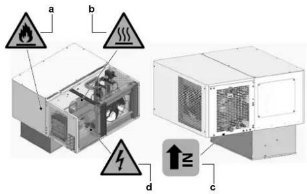
LMCEY1A/W
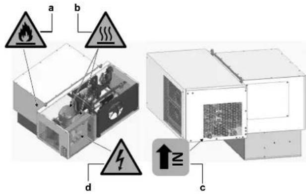
LMCEY2A/W
a Flammable materials
Thermal hazard
Water inlet indication (LMCEY1W+LMCEY2W only)
d Electrical hazard
3.5 Possible options for the unit

INFORMATION
Certain options may NOT be available in your country.

NOTICE
The use of accessories and/or options other than those approved by Daikin may cause system malfunctions and automatically void the warranty, relieving the manufacturer from any damage caused to persons, animals and/or property.
Four cable glands (f) are provided to bring the option cables into the unit.
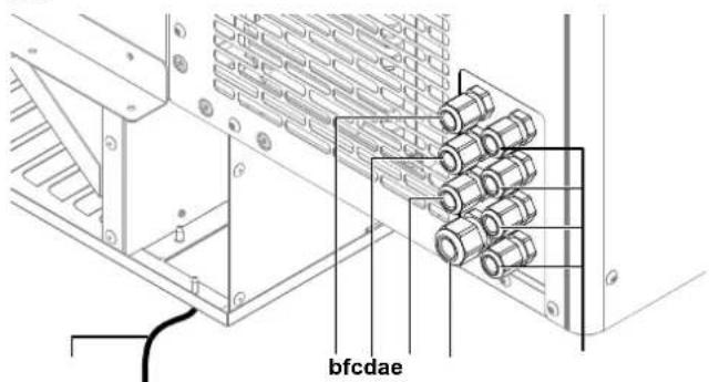
a Cell light wire (2 m), C3 labelled
b Remote control panel, pre-wired (5 m)
Door heater, pre-wired (5 m), C2 labelled
d Door switch, pre-wired (5 m), C4 labelled
e Power supply, pre-wired (5 m), C1 labelled
f For optional use
Door switch (3MCT014ACC)
To reduce frost on the evaporator, the door switch interrupts the unit operation when the cold room door is open. It also controls the cell light. The door switch is an option.
If the door remains open for longer than the value of parameter Add, control resumes in any case. The light remains on, the measurement shown on the display flashes, the buzzer and the alarm relay (if enabled) are activated, and the temperature alarms are enabled with 60 minutes of delay.
Door heater
For low temperature applications it is suggested to install a door heater. It prevents the door from freezing. The choice for the most appropriate door heater is left to the installer or cold room manufacturer. Sometimes the door heater is already included in the pre-fabricated door kit.

INFORMATION
The door heater is only necessary for low temperature applications.
Cell light (1KIT862ACC)
The light is ON when the cold room door is open. The time during which the light stays on after closing the door is set by the parameter H14, and can be set from 0 to 240 minutes. See "4.3.3 To change the parameters" [▶ 12].
The cell light can also be controlled by the user interface or via the Daikin apps.
The cell light is an option.

INFORMATION
There are 4 free cable glands available for options. Only 4 extra options can be installed.
Alarm
An alarm feature can be installed (light or sound).
Router
The unit (or multiple units) can be connected to the network through a router, available as an option.
uBOSS Wi-Fi (wireless, 3MCB002ACC)
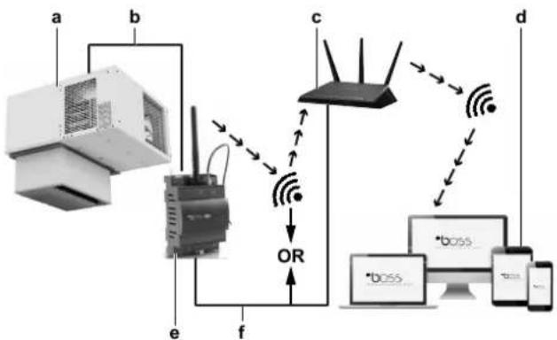
a LMC unit
bRS485 cable
c Access point (external router)
d Devices
e Gateway uBOSS
f LAN cable
OR Choice between WiFi or LAN cable
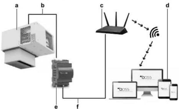
uBOSS Ethernet (wired, 3MCB001ACC)
a LMC unit
b RS485 cable
c Access point (external router)
d Devices
e Gateway BOSS
f LAN cable
Combining multiple units
To interconnect multiple units, a communication cable must be used. See "To install multiple units" in the installation manual.
4 User interface

CAUTION

- NEVER touch the internal parts of the controller.
- Do NOT open up the controller. Some parts inside are dangerous to touch and appliance problems may happen.
This operation manual offers a non-exhaustive overview of the main functions of the system.

INFORMATION
Use only those combinations of controls and programs which are mentioned in the manufacturer's instruction manual.
4.1 Overview
The user interface display features three digits, with a sign for below-zero temperatures and a decimal point. It has a built-in alarm buzzer and nine icons/buptions.

INFORMATION
If there is an active alarm the buzzer will sound. Press any button to mute the buzzer.
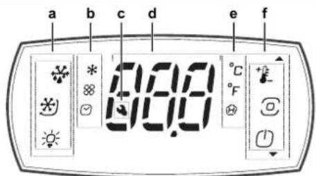
a Buttons
b lcons
c Alarm icon
d Display
e |cons
f Buttons
Meaning of icons that appear on the display
| Icon | Description |
| + | Setpoint/Up arrow |
| Program | |
| On-Off/Down arrow | |
| Defrost | |
| Continuous cycle (not enabled) | |
| Light |
| Icon | Description |
| HACCP | |
| Alarm log | |
| Auxiliary output | |
| Compressor | |
| Evaporator fan | |
| Clock | |
| °C | °Celsius |
| °F | °Fahrenheit |
| Service/Maintenance |
Meaning of signals that appear on the display
Signals are messages shown on the display to notify the user of the control procedures in progress (e.g. defrost) or to confirm keypad input.
| Message | Meaning |
| BLE | Bluetooth™ connection in progress |
| dEF | Defrost running |
| Loc | Display locked |
| Off | Switch OFF |
| On | Switch ON |
4.2 Basic functions
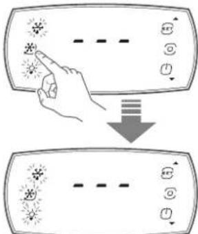
4.2.1 To unlock the user interface
To unlock the user interface
1 Press any button.
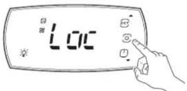
Result: The display shows the message "Loc".
2 Press the PROGRAM button for three seconds to exit lock mode.

Result: The display shows three dashes in sequence.
4.2.2 To start up
1 Unlock the user interface. See "4.2.1 To unlock the user interface" [▶ 9].
2 Turn the unit on by pushing the on-off/down arrow button on the user interface.
Result: The display switches on. It briefly shows the firmware version.
Result: The unit starts up.

INFORMATION
The compressor starts up after a pre-set delay (parameter). This function is useful to protect the compressor and the relay from power cycling in the event of repeating power outages. Defrosting (if required) also starts after this delay. The whole process may take a few minutes. Then the compressor will restart in cooling mode.

INFORMATION
In the off status of the unit, the maximum interval between consecutive defrosts is always updated, in order to maintain the cyclical nature of this interval. If a defrost interval expires while the unit is off, the event is recorded. When the unit is switched on again, a defrost request is then generated.
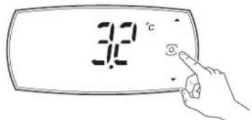
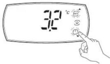
4.2.3 To set the temperature
1 Unlock the user interface. See "4.2.1 To unlock the user interface" [▶ 9].

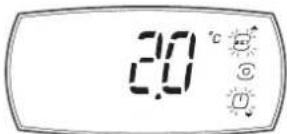
2 Press the Setpoint/Up arrow button:
3 Use the UP and DOWN buttons to change the temperature setpoint.
Result: The setpoint has changed.
4.2.4 To shut down
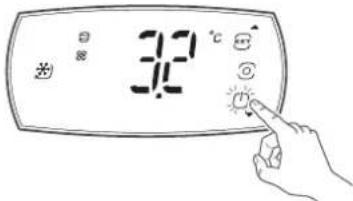
1 Unlock the user interface. See "4.2.1 To unlock the user interface" [▶ 9].
2 Turn the unit off by pushing the on-off/down arrow button on the user interface.
Result: The compressor protection times are observed.
Result: Defrosting is forcibly terminated and will not resume when switching on.
4.2.5 To navigate between screens
4.2.6 To change the status of an actuator

INFORMATION
If no button is pressed, the terminal will return to the standard display after 7 seconds.
1 Unlock the user interface. See "4.2.1 To unlock the user interface" [▶ 9].
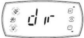
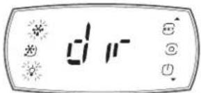
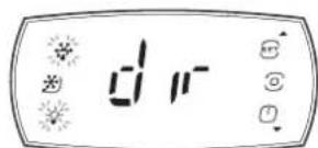
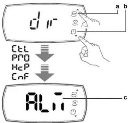
2 Press the PROGRAM button to enter "dir" mode.
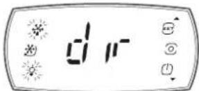
Result: The display shows "dir". The buttons that are on steady indicate that the corresponding actuator/function is active. The buttons that are flashing indicate that the actuator/function is not active.
3 Press a button (e.g. the continuous cycle button).
Result: The status changes (e.g. from active to not active).
4.2.7 To change the status of a direct function

INFORMATION
If no button is pressed, after 20 seconds the terminal will automatically return to the standard display.
1 Unlock the user interface. See "4.2.1 To unlock the user interface" [▶ 9].
2 Press the PROGRAM button to enter "dir" mode.
Result: The display shows "dir".

Changing the direct function:
3 Press the PROGRAM button in the "dir" screen.
Result: The display shows the first direct function screen (e.g. "Fr").
4 Press the UP and DOWN buttons to navigate the menu.
5 Press the PROGRAM button when arrived at the direct function screen you want to change (e.g. "Eco").
Result: You entered the direct function.
6 Press the UP and DOWN buttons to change the setting (e.g. change to "On").
7 Press the PROGRAM button to confirm the new setting.
Result: The display goes back to the direct function screen (e.g. "Eco").
8 Press the UP and DOWN buttons to navigate the menu. Scroll to the next direct function of which you want to change the status.
When finished changing direct functions status:
9 Scroll to the "ESC" screen.
10 Press the PROGRAM button.
Result: The display goes back to the actuator/function direct ("dir") activation screen.
Meaning of symbols that appear on the display
| Display | Menu Description | |
| /5 | ●Pro | Unit of measure (0: °C, 1: °F) |
| Ad | ●ALM | Delay time for high and low temperature alarms |
| Add | ●ALM | Door alarm delay and high temperature alarm delay after door opening |
| AH | ●ALM | Relative high temperature alarm threshold |
| Display | Menu Description | |
| AL | ALM | Relative low temperature alarm threshold |
| Eco | dir | Activate ECO mode (0: OFF, 1: ON) |
| Fr | dir | Firmware version (only reading) |
| HAn | HcP | Number of type HA alarms (only reading) |
| Hb | CnF | Enable buzzer (0: disabled, 1: enabled) |
| HFn | HcP | Number of type HF alarms (only reading) |
| HU | CtI | Set humidity level (not enabled) |
| PSd | PSd | Service menu |
| rHP | HcP | Reset event HACCP event log |
| rSA | ALM | Reset alarms |
| SAh | dir | Display alarm log (only reading) |
| Sc | dir | Condenser probe (only reading) |
| Sm | dir | Same as SrG (only reading) |
| SrG | dir | Control probe (only reading) |
| St | CtI | Set temperature set point |
| StH | CtI | Set humidity set point (not enabled) |
4.3 Configuration

INFORMATION
Use only those combinations of controls and programs which are mentioned in the manufacturer's instruction manual.
4.3.1 To connect your device with Daikin User

INFORMATION
Setting parameters is best done via the app (Daikin User or Daikin Installer). However, some of the parameters can also be set via the user interface.
The Daikin app is required to configure the controller, set up parameters or check trends and information.
From a mobile device (smartphone, tablet), via BLE (Bluetooth Low Energy), the Daikin User app can set the set point, launch manually a defrost, turn on and off the cell room light (if present) and the ECO mode.
It is also possible to view and download the trend related to the HACCP function.
Procedure to install the app:
1 Download the "Daikin User" app.
2 On the mobile device, start the app.
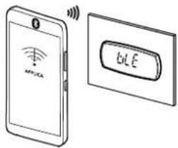
3 Turn on Bluetooth on your device. Open Daikin User and select the Bluetooth icon to show the available devices.
4 Select "BLUETOOTH SCAN" to view the controller devices available within a range of 10 m.
5 Select the device to connect to.
Result: "BLE" will blink on the user interface display to confirm that the connection is established.


INFORMATION
During the first connection, the app (Daikin User or Daikin Installer) synchronises with the controller software via a cloud connection. This means that an internet connection is required, at least for this first connection. If not, the required packet can also be retrieved from the cloud as soon as the connection is restored (via the "Packet Manager" section of the app).

INFORMATION
To change the device ID (Bluetooth name) of the unit, navigate to "Home / Service Area" once the unit is connected.

INFORMATION
Bluetooth frequency range from 2.4 GHz to 2.4835 GHz. Bluetooth power level: +4 dBm.

INFORMATION
The unit is equipped with a backup battery to ensure the correct working of the unit clock in case of power failures.
During the first installation and/or after long periods of non-use of the unit, the backup battery could be discharged causing the clock alarm "Etc" blinking on the HMI.
In this case, with the Daikin App, while the unit is in StandBy mode, update Date & Time in Setting->Device -- >Set data/time.
The unit will take automatically date and time from the connected device clock.
Please See "8.1 Error codes: Overview" in the Operation Manual.
4.3.2 To save the factory parameters

INFORMATION
Before changing any parameters, be sure to save the factory parameter configuration so that you can restore it at any time.
Connect your device with Daikin User. See "4.3.1 To connect your device with Daikin User" [▶ 11]
1 Use the "hamburger" menu at the top left of the screen to go to the "Parameter list".
2 Click on the 3 dots at the top right of the screen and select "Create configuration".
3 Save the configuration as "Default configuration".
4 Now the factory configuration is saved and can be restored, if necessary, by clicking the "hamburger" menu Configurations Default configuration Apply.
4.3.3 To change the parameters

INFORMATION
Before changing any parameters, be sure to save the factory parameter configuration so that you can restore it at any time.
1 Unlock the user interface. See "4.2.1 To unlock the user interface" [▶ 9].
2 Press the PROGRAM button to enter "dir" mode.
Result: The display shows "dir".
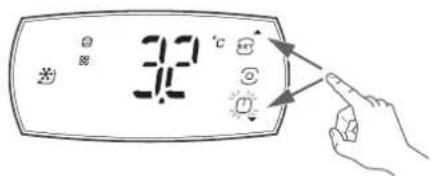
3 Use the UP (a) and DOWN (b) buttons to navigate towards the desired menu, then press the PROGRAM (c) button to enter the menu (e.g. Ctrl).
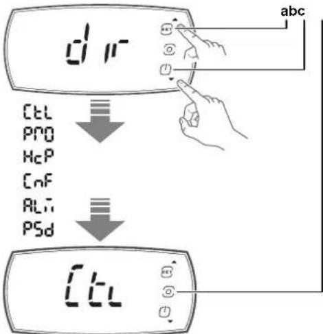
a UP button
bDOWN button
c PROGRAM button
tL Control menu
Pro Display probes menu
HcP HACCP menu
CnF Configuration menu
ALM Alarms menu
PSd Service menu
ESC Exit the menu loop
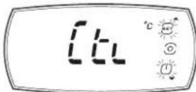
4 Use the UP (a) and DOWN (b) buttons to navigate towards the menu item, then press the PROGRAM (c) button to display the parameter value (e.g., St).
5 Use the UP (a) and DOWN (b) buttons to change the setting (e.g. Press UP/DOWN to modify the value).
6 Press the PROGRAM (c) button to save setting and return to the menu.

INFORMATION
If the PROGRAM button is not pressed, the setting will not be saved.
7 Use UP/DOWN to select "ESC" and press the PROGRAM (c) button to return to the parameter categories.
8 Use UP/DOWN to move to the next category and follow steps 3 to 7 to set the other parameters.
9 Once the setting have been made, to exit the categories select "ESC" and press the PROGRAM (c) button.
4.3.4 Parameters
| Name | Description Default Min. Max. UoM Menu | (a) | App | ||||
| \( /5^{(b)} \) | Unit of measure:0 : °C1 : °F | 0 0 1 | ● | Pro | ● | ||
| \( Add^{(b)} \) | Door alarm delay and high temperature alarm delay after door opening | 15 1 240 min ● | ALM | ● | |||
| \( AH^{(b)} \) | Relative high temperature alarm threshold(c) | 5 0 555/999 | ALM | ● | |||
| \( AL^{(b)} \) | Relative low temperature alarm threshold(c) | 0 0 200/360 | ALM | ● | |||
| \( dAs^{(b)} \) | DAY status/ECO mode | 1 0 1 | ● | ||||
| \( Eco^{(d)} \) | Eco mode status:0 : OFF1 : ON | 1 0 1 | ● | dir | |||
| \( H14^{(b)} \) | Time light stays on after closing the door | 0 0 240 min | ● | ||||
| HAn | Number of type HA alarms (read only) | 0 0 6 | ● | HcP | |||
| \( Hb^{(b)} \) | Buzzer:0 : disabled1 : enabled | 1 0 1 | ● | CnF | ● | ||
| HFn | Number of type HF alarms (read-only) | 0 0 6 | ● | HcP | ● | ||
| \( Htd^{(b)} \) | HACCP alarm delay, 0: monitoring disabled | 0 0 240 | ● | ||||
| \( On^{(b)} \) | ON/OFF command (button on user interface):0 : Off1 : On | 0 0 1 | ● | ||||
| \( PDU^{(b)} \) | User password | 0 0 999 | ● | ||||
| rHP | Reset HACCP event log | 0 0 1 | ● | HcP | ● | ||
| rSA | Reset alarms | 0 0 1 | ● | ALM | |||
| SAK | Alarm history visualisation (read only) | - | - | - | |||
| SrG | Regulation sensor (cold room temperature) (read only) | 0 | 0 | 0 | °C/°F | ●dir | |
| \( St^{(b)} \) | Temperature control setpoint | -25 | -25/-13 | 10/50 | °C/°F | ●Ctrl | ● |
| td1-d(b) | Time band 1 for scheduled defrost-day | 0 0 1 | ● | ||||
| td1-time(b) | Time datatype 1 | 0:00:00 | 0:00:00 | 23:59:59 | ● | ||
| td2-d(b) | Time band 2 for scheduled defrost-day | 0 0 1 | ● | ||||
| td2-time(b) | Time datatype 2 | 0:00:00 | 0:00:00 | 23:59:59 | ● | ||
| td3-d(b) | Time band 3 for scheduled defrost-day | 0 0 1 | ● | ||||
| td3-time(b) | Time datatype 3 | 0:00:00 | 0:00:00 | 23:59:59 | ● | ||
| td4-d(b) | Time band 4 for scheduled defrost-day | 0 0 1 | ● | ||||
| td4-time(b) | Time datatype 4 | 0:00:00 | 0:00:00 | 23:59:59 | ● | ||
| td5-d(b) | Time band 5 for scheduled defrost-day | 0 0 1 | ● | ||||
| td5-time(b) | Time datatype 5 | 0:00:00 | 0:00:00 | 23:59:59 | ● | ||
| td6-d(b) | Time band 6 for scheduled defrost-day | 0 0 1 | ● | ||||
| td6-time(b) | Time datatype 6 | 0:00:00 | 0:00:00 | 23:59:59 | ● | ||
| td7-d(b) | Time band 7 for scheduled defrost-day | 0 0 1 | ● | ||||
| td7-time(b) | Time datatype 7 | 0:00:00 | 0:00:00 | 23:59:59 | ● | ||
| td8-d(b) | Time band 8 for scheduled defrost-day | 0 0 1 | ● | ||||
4 User interface
| Name | Description Default Min. Max. UoM | Menu | (a) | App | |||
| td8-time(b) | Time datatype 8 0:00:00 0:00:00 23:59:59 ● | ||||||
| tE1-d(b) | End time band 1 for ECO mode - day 0 0 1 ● | ||||||
| tE1-time(b) | End time datatype 1 0:00:00 0:00:00 23:59:59 ● | ||||||
| tE2-d(b) | End time band 2 for ECO mode - day 0 0 1 ● | ||||||
| tE2-time(b) | End time datatype 2 0:00:00 0:00:00 23:59:59 ● | ||||||
| tE3-d(b) | End time band 3 for ECO mode - day 0 0 1 ● | ||||||
| tE3-time(b) | End time datatype 3 0:00:00 0:00:00 23:59:59 ● | ||||||
| tE4-d(b) | End time band 4 for ECO mode - day 0 0 1 ● | ||||||
| tE4-time(b) | End time datatype 4 0:00:00 0:00:00 23:59:59 ● | ||||||
| tE5-d(b) | End time band 5 for ECO mode - day 0 0 1 ● | ||||||
| tE5-time(b) | End time datatype 5 0:00:00 0:00:00 23:59:59 ● | ||||||
| tE6-d(b) | End time band 6 for ECO mode - day 0 0 1 ● | ||||||
| tE6-time(b) | End time datatype 6 0:00:00 0:00:00 23:59:59 ● | ||||||
| tE7-d(b) | End time band 7 for ECO mode - day 0 0 1 ● | ||||||
| tE7-time(b) | End time datatype 7 0:00:00 0:00:00 23:59:59 ● | ||||||
| tE8-d(b) | End time band 8 for ECO mode - day 0 0 1 ● | ||||||
| tE8-time(b) | End time datatype 8 0:00:00 0:00:00 23:59:59 ● | ||||||
| tS1-d(b) | Start time band 1 for ECO mode - day 0 0 1 ● | ||||||
| tS1-time(b) | Start time datatype 1 0:00:00 0:00:00 23:59:59 ● | ||||||
| tS2-d(b) | Start time band 2 for ECO mode - day 0 0 1 ● | ||||||
| tS2-time(b) | Start time datatype 2 0:00:00 0:00:00 23:59:59 ● | ||||||
| tS3-d(b) | Start time band 3 for ECO mode - day 0 0 1 ● | ||||||
| tS3-time(b) | Start time datatype 3 0:00:00 0:00:00 23:59:59 ● | ||||||
| tS4-d(b) | Start time band 4 for ECO mode - day 0 0 1 ● | ||||||
| tS4-time(b) | Start time datatype 4 0:00:00 0:00:00 23:59:59 ● | ||||||
| tS5-d(b) | Start time band 5 for ECO mode - day 0 0 1 ● | ||||||
| tS5-time(b) | Start time datatype 5 0:00:00 0:00:00 23:59:59 ● | ||||||
| tS6-d(b) | Start time band 6 for ECO mode - day 0 0 1 ● | ||||||
| tS6-time(b) | Start time datatype 6 0:00:00 0:00:00 23:59:59 ● | ||||||
| tS7-d(b) | Start time band 7 for ECO mode - day 0 0 1 ● | ||||||
| tS7-time(b) | Start time datatype 7 0:00:00 0:00:00 23:59:59 ● | ||||||
| tS8-d(b) | Start time band 8 for ECO mode - day 0 0 1 ● | ||||||
| tS8-time(b) | Start time datatype 8 0:00:00 0:00:00 23:59:59 ● |
The menu where the parameter is situated is indicated in this column.
A modification of the parameters other than those shown in the table may affect the proper operation of the unit. ONLY have them changed by a professional.
Parameters AH and AL are used to set the thresholds relative to the set point for the high and low temperature alarms.
To protect the refrigerated products, management of these two alarm thresholds will override normal control:
AL (low temperature alarm threshold): when the coldroom temperature is lower than the threshold AL, the compressor is immediately stopped.
- AH (high temperature alarm threshold): when the coldroom temperature is higher than the threshold AH, the compressor works at maximum speed.
The unit is equipped with the possibility to enable the Eco mode, to save energy at certain times (e.g. at night).
The function can be activated by the user and must be evaluated in alignment with HACCP procedures.
To reduce energy consumption, during Eco operation, the set point of the unit is increased by the value as set in parameter r4.
Eco operation can be activated on the user interface or by using the Daikin app, by pushing the Eco icon in the home page or by changing the time bands, with the same priority.
4.4 To set the shared functions for multiple units

NOTICE
Make sure the software version of all units is the same and up-to-date. If it is not the latest version, update the software, otherwise the units may not work properly due to suboptimal communication.

INFORMATION
In case the secondary unit controller is offline, the primary unit controller will keep all functions working, without taking care of the specific secondary unit controller that is no longer available (network regulation, network defrost, door,...).
From the secondary unit controller side, the controller will try to guarantee the cooling, so it will regulate on the cold room temperature.
Lights
Lights can be connected to all controllers in the network and the light status is always synchronised. Each controller will turn the lights on and off simultaneously.
Door open
The door microswitch must be connected to the primary unit controller in the network.
As for the lights, also the door status is shared to all controllers. Every controller knows if the door(s) is/are open or not, and each controller can perform actions.
Network temperature regulation

INFORMATION
To change parameters related to this functionality, "Service" level access is required.
The temperature regulation can be performed in two ways depending on the parameter "nrt" with the following values:
- 0: The relative controller regulates through the probe connected to itself.
- 1: The relative controller regulates through the probe connected to the primary unit controller.
The network logic allows avoiding simultaneous starts of compressors. Using the "SSd" parameter it is possible to set a delay between starts of different LMCEY units.
If it is necessary to start several units at the same time, the first unit to signal to start will be the first one to start. After "SSd" the next unit will also start and so on (See the example below).
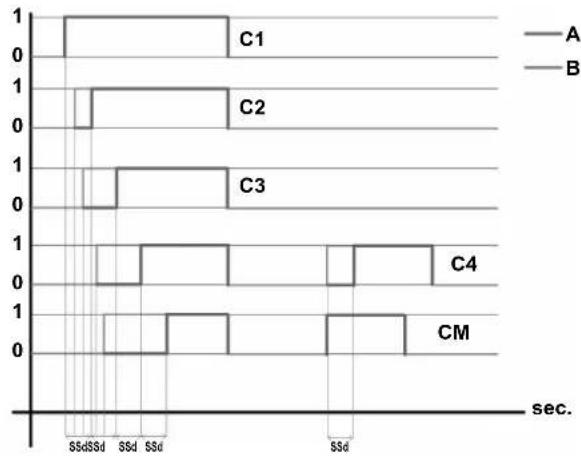
1 On
0 Off
A Compressor status
B Request status
C1 Compressor secondary unit 1
C2 Compressor secondary unit 2
C3 Compressor secondary unit 3
C4 Compressor secondary unit 4
CM Compressor primary unit
SSd Delay between start up [s]
Note: LMCEY2A/W units have two compressors, but work in a similar way. The two compressors of the same unit work synchronously.
Network defrost

INFORMATION
To change parameters related to this functionality, "Service" level access is required.
It is possible to enable/disable this functionality for each controller separately.
Defrost can be synchronised between the primary unit controller and secondary unit controllers using parameters dS_1, dS_2, dS_3, and dS_4 with the following values:
- 0: No synchronisation performed.
1:Only starting.
Only starting: secondary unit controllers will start to defrost at the same time as the primary unit controller, and all controllers can finish in different moments.
- 2: Start & Stop.
Start & Stop: secondary unit controllers will start to defrost at the same time as the primary unit controller. If one controller ends defrosting before the others, the corresponding defrost relay is de-energised and the dripping phase will only start when all other controllers have finished the defrosting phase.
ds_1=0
ds2=1
ds-3=2
ds_4=2
d2 = 0
ds_1 = 0
ds2=1
ds-3=2
ds_4=2
d2 = 1
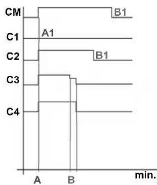
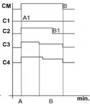
A Start
A1 Start not synchronised
B End synchronised
B1 End not synchronised
C1 Controller secondary unit 1
C2 Controller secondary unit 2
C3 Controller secondary unit 3
C4 Controller secondary unit 4
CM Primary unit controller
dS1~4 Defrost synchronisation parameters
d2 Network end defrost synchronised for primary unit
Local defrosting on a LMCEY unit is still possible in two ways:
- Manually (from app, supervisory system or user interface).
- If not manually started, each unit will perform a defrost every 4 hours to allow the correct operation of the unit.
4.5 About the alarms
4.5.1 To enter the alarm screen
1 Unlock the user interface. See "4.2.1 To unlock the user interface" [▶ 9].
2 Press the PROGRAM button to enter menus.
Result: The display shows "dir".
3 Use the UP and DOWN buttons to navigate towards the desired menu, then use the PROGRAM button to enter the menu "ALM" (alarm).
4Userinterface
a UP button
bDOWN button
c PROGRAM button

INFORMATION
If no button is pressed, the terminal will return to the standard display after 7 seconds.
4.5.2 About types of malfunctions
When a malfunction is detected:
- The error code is shown on the display, alternating with the main value. This allows immediate identification of the malfunction.
- The "service" icon is shown on the display.
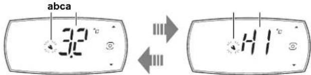
a "Service" icon
b Main value
c Error code
There are 2 types of malfunctions:
- Warning
The buzzer does not sound.
- No relay is activated.
Errors belonging to this category include defrost ended after maximum time, dirty condenser, HACCP alarms and configuration errors.
- Alarm
The buzzer sounds.
The concerning relay is activated.
This category includes alarms for which the relay is configured as an alarm, probe errors, temperature alarms, etc.

INFORMATION
If there is an active alarm the buzzer will sound. Press any button to mute the buzzer.
Take into account that:
Alarms and warnings are identified by error codes. For the error code table, see "8 Troubleshooting" [▶ 20].
If more than one warning/alarm occurs, they are displayed in sequence.
The warning and alarm signals can be immediate or delayed by parameter.
4.5.3 To reset an alarm or warning
Both warnings and alarms can be reset automatically, manually, or semi-automatically (see "8.1 Error codes: Overview" [▶ 22]):
Automatic: when the cause is no longer present, the alarm also ceases.
- Manual: when the cause is no longer present, the alarm remains active until manually reset by parameter.
The alarms can be reset manually by setting parameter rSA to "1", via the user terminal or in the Daikin app (Bluetooth connection only), using the specific command on the alarms page.
If the condition that generated the alarm is still present, the alarm is reactivated after resetting.
4.5.4 About the alarm log
Alarm log
When an alarm is cleared, it is stored in the alarm log containing a maximum of 5 alarms, in a FIFO list (the 6th alarm overwrites the first alarm, and so on). The error log is accessible via the user terminal, via supervisor or the Daikin apps (Bluetooth connection only).
The controller can record both periodic and event logs, which can then be viewed and downloaded using the Daikin apps.
1 To view the periodic logs in Daikin User: Select Trend in the hamburger menu (tab) Logs.
2 To view the event logs in Daikin User: Select Trend in the hamburger menu (tab) Events.
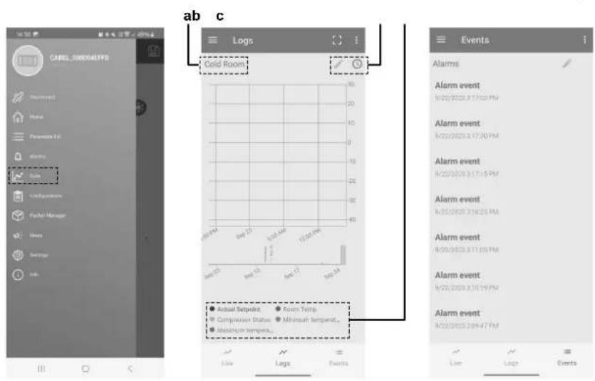
a Preset
b Periodically logged variables c Legend
The log view is pre-set, however it CAN be changed using the legend choice. In addition, the pre-set views loaded on the device allow the main values to be filtered (temperature, HACCP alarms, blackouts, etc.). To download the logs, use the drop-down menu at the top right.
The periodic logs record the main values at regular intervals, as shown in the table below.
| Logged value | UOM Period |
| Control temperature | °C/°F 5 min |
| Current temperature set point. | °C/°F 1 h |
| Maximum temperature in the period | °C/°F 1 h |
| Minimum temperature in the period | °C/°F 1 h |
| Current evaporation temperature | °C/°F 1 h |
| Current condensing temperature | °C/°F 1 h |
| Compressor, minutes ON in the period | min 1 h |
| Compressor, starts in the period | -1 h |
| Evaporator fan, minutes ON in the period | min 1 h |
Event logs are recorded when specific conditions occur, and can be used to store certain related values, as shown in the table below.
The type of alarm recorded in the log can be identified using the alarm information (see "8.1 Error codes: Overview" [▶ 22]).
| Logged value | Event Other recorded values | Sample s* | Limit s | |
| Alarm | Alarm activation | Number of the active alarm with highest priority. Alarm status (active/ceased) | 20 max | 255 alarm |
| Blackout | Device ON Power failure duration in minutes | 20 | 1000 hours | |
| HACCP alarms | HA or HF alarm | Type HA or HF alarm | 10 | - |
- The samples are stored in a circular FIFO list (e.g. for the alarms, the 21st alarm overwrites the first alarm, and so on).

NOTICE
Changing the time set on the controller by more than 140 minutes will clear the stored logs.
The alarm log can be deleted using the Daikin Apps (Bluetooth connection only) using the specific command on the alarms page.

INFORMATION
Deleting the alarm log is irreversible.
For the alarm list with the codes and descriptions, see "8.1 Error codes: Overview" [▶ 22].
5 Operation
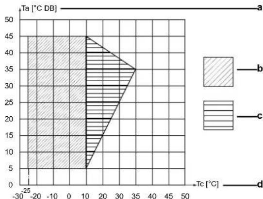
5.1 Operation range
For air cooled units
| Temperature type | Temperature range |
| Ambient temperature | +5~+45°C |
| Temperature type | Temperature range | |
| Cooling temperature | Low temperature setting (freezer) | From -25°C |
| Medium temperature setting (cooler) | Up to +10°C | |
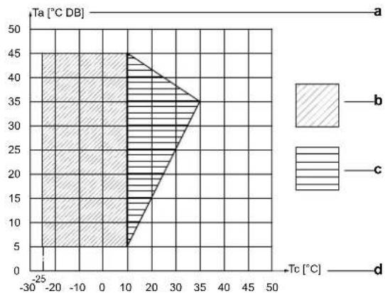
a Ambient temperature (Ta)
bOperation range
c Pull-down area
Cold room temperature (Tc)
For water cooled units
| Temperature type | Temperature range | |
| Ambient temperature | +5~+45°C | |
| Water temperature | +5~+48°C | |
| Cooling temperature | Low temperature setting (freezer) | From -25°C |
| Medium temperature setting (cooler) | Up to +10°C | |
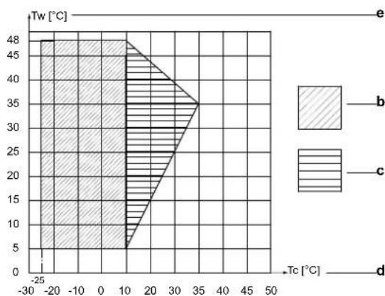
a Ambient temperature (Ta)
bOperation range
c Pull-down area
Cold room temperature (Tc)
Water temperature (Tw)
Before putting the unit into operation, make sure that the quality of the water used to feed the unit condenser(s) respects the table below. The manufacturer is not responsible for damage or malfunctioning of the equipment caused by improperly treated water.

CAUTION
Do not add glycol or other additives to water. The use of fluids other than those specified by the manufacturer may affect the unit capacity and reliability.
| WATER CONTENT | CONCENTRATION (mg/l or ppm) |
| Alkalinity (HCO3-) | 70-300 |
| Sulphate (SO42-) | <70 |
| HCO3-/SO42- | >1.0 |
| Electrical conductivity | 10-500 μS/cm |
| pH | 7.5-9.0 |
| Ammonium (NH4+) | <2 |
| Chlorides (Cl-) | <50 |
| Free chlorine (Cl2) | <1 |
| Hydrogen sulfide (H2S) | <0.05 |
| Free (aggressive) carbon dioxide (CO2) | <5 |
| Total hardness (°dH) | 4.0-8.5 |
| Nitrate (NO3-) | <100 |
| Iron (Fe) | <0.2 |
| Aluminium (Al) | <0.2 |
| Manganese (Mn) | <0.1 |
5.2 Operation procedure
- Read the documentation carefully before operating the unit to ensure the best possible performance.
- Turn ON the unit before storing the refrigerated goods. Varies from 15 to 30 minutes, depending on the ambient temperature.
- Choose the correct temperature setting for the product that is to be stored (see "4 User interface" [▶ 9]).
- A door micro switch interrupts the unit operation and turns on and off the cold room lamp when the cold room door is opened. The cold room lamp can also be switched on and off via the user interface or via the Daikin apps.
- Bluetooth makes it possible to check and control the unit via the Daikin User app.
- Multiple units (up to 5) can be combined within one cold room. They will then operate according to the primary/secondary principle.
Advantages:
Higher cooling capacity.
Redundancy should a unit break down.
- Better airflow.
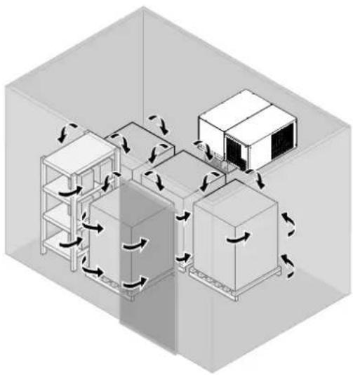
5.3 Storing the goods

NOTICE
Do not cover the air intake and outlet openings towards the condenser and evaporator of the unit.
Maintaining the right temperature guarantees the preservation of the quality of the stored goods.
Air circulation is of absolute importance to keep a uniform temperature throughout the entire cold room. Insufficient air circulation can cause heat pockets or ice formation.
For this reason:
- Use pallets or racks that facilitate air circulation under the goods.
- Place the goods away from the cold room walls. Use spacers if necessary.
- Leave a space of approximately 20cm between the goods and the cold room ceiling.
- Stack heat generating products, such as fruit and vegetables, in a way to create sufficient space to remove the generated heat by cold air circulation.
- Stack products which do not generate heat, such as meat and frozen foods, close to each other toward the center of the cold room.

WARNING


Daikin is not responsible for cold room safety.
Make sure that no people are left in the cold room before you close the doors:
- Risk of suffocation. 12 ~m^3 must be left empty inside the cold room.
- Risk of frostbite.
- Risk of freezing to death.
5.4 HACCP alarms
This unit is provided with the HACCP control function. The HACCP (Hazard Analysis and Critical Control Point) is a management system designed to identify health hazards and to establish strategies to prevent, eliminate, or reduce their occurrence.
The HACCP control function embedded into this unit allows control and monitoring of the critical control point (refrigeration temperature).
It is also possible to download reports demonstrating compliance with current law.
By using the Daikin app, it is possible to enable the HACCP data recording on the unit by changing the parameter "Htd". See "4.3 Configuration" [▶ 11].
The initial setting of the "Htd" parameter is "0", meaning that HACCP data recording is disabled.
Specific alarms
There are specific alarms for controlling the operating temperature, recording any anomalies due to power failures or an increase in the temperature due to other causes (breakages, extreme operating conditions, user errors, etc.).
Two types of potentially critical HACCP events are managed:
- Type "HA" alarms, high temperature during operation:
The type "HA" alarm is generated if during normal operation the temperature read by the control probe exceeds the high temperature threshold for 60 minutes (delay time for high and low temperature alarms) + "Htd" (HACCP alarm delay). Consequently, compared to the normal high temperature alarm already signalled by the controller, the type "HA" HACCP alarm is delayed by a further time "Htd" specifically for HACCP recording.
Example: The critical temperature was exceeded, the alarm was not managed and the temperature remained above the threshold for longer than the maximum tolerable time (thresholds defined by site HACCP procedures).
| Par. | Description Def. | Min. Max. UOM Menu App | |||||
| Htd | HACCP alarm delay | 0 (monitoring disabled) | 0 240 Min | ● | |||
| HAn | Number of type HA alarms | 0 0 15 | - | ● | HcP | ● | |
| HA1 , HA2 , HA3 | Activation date and time of the first, second and third type HA alarm | ... | ... | ... | - | ● | |
- Type "HF" alarms, high temperature after power failure:
The type "HF" HACCP alarm is generated following a power failure, if when power returns the temperature read by the control probe exceeds the "AH" high temperature threshold. "HFn" indicates the number of type "HF" alarms activated.
Example: The unit was powered off. When restarted, the temperature is above the threshold and does not return to an acceptable level within an appropriate time (parameters defined by site HACCP procedures).
| Par. | Description | Def. | Min. | Max. | UOM | Menu | App |
| HFn | Number of type HF alarms | 0 | 0 15 | - | - | HcP | - |
| HF1, HF2, HF3 | Activation date and time of the first, second and third type HF alarm | ... | ... | ... | - | - |
When an alarm occurs, the HACCP icon comes on, the display shows the alarm code, the alarm is logged and the alarm relay and buzzer are activated.
The "HA" and "HF" alarms can be reset using the Daikin app. See "4.5.3 To reset an alarm or warning" [▶ 16].
The HACCP event log can be deleted by using the Daikin app, via the drop-down menu on the side, selecting "Alarms -> Alarm history -> Clear logs".

NOTICE
Deleting the HACCP event log is irreversible.
6 Energy saving and optimum operation
If circumstances allow:
- Do not place unfrozen liquids or foodstuffs in the cold room (when used as freezer).
- Reduce the opening frequency of the cold room doors.
Always:
- Reduce the opening time of the cold room doors.
- Make sure that cold room doors are perfectly tight.
- Make sure that a good airflow is possible between the stored goods.
- Check that the evaporator is ice-free. Ice forms on the evaporator preventing air from flowing regularly.
7 Maintenance and service

INFORMATION
Suitable maintenance is crucial for obtaining longer life, perfect working conditions and high efficiency of the unit. It also ensures the proper functioning of the safety devices provided by the manufacturer.
7.1 Cleaning the unit
7.1.1 To clean the exterior

NOTICE
To clean the unit enclosure:
- Do not use any cleaning agents or chemicals.

WARNING
Do NOT use water for cleaning. Use of water can damage electrical components.
Clean with a soft cloth. If it is difficult to remove stains, use water or neutral detergent and wipe with a dry cloth.
7.1.2 To clean the interior

NOTICE
To clean the unit enclosure:
- Do not use any cleaning agents or chemicals.

DANGER: RISK OF ELECTROCUTION
- Turn OFF all power supply before removing the switch box cover, connecting electrical wiring or touching electrical parts.
- Disconnect the power supply for more than 10 minutes, and measure the voltage at the terminals of main circuit capacitors or electrical components before servicing. The voltage MUST be less than 50 V DC before you can touch electrical components. For the location of the terminals, see the wiring diagram.
- Do NOT touch electrical components with wet hands.
- Do NOT leave the unit unattended when the service cover is removed.

CAUTION


Do NOT touch the heat exchanger fins. These fins are sharp and could result in cutting injuries. Wear safety gloves if you have to work on or around the heat exchanger fins.

WARNING
Do NOT use water for cleaning. Use of water can damage electrical components.
Good operation of the unit requires the condenser and evaporator to be clean. The frequency of cleaning depends on the environment where the unit is installed.

INFORMATION
Under normal working conditions the condenser and evaporator should only be cleaned during scheduled maintenance inspections.
Condenser heat exchanger cleaning
1 Turn off the unit.
2 Clean the condenser heat exchanger with a long-haired brush or by blowing (low pressure) air from the inside outwards.

NOTICE
Do not use high-pressure air to clean the condenser heat exchanger fins. It will damage them and prevent proper operation of the condenser heat exchanger.

WARNING
Do NOT use water for cleaning. Use of water can damage electrical components.
Should the fins nevertheless get bent:
3 Straighten them carefully using a fin comb for cleaning/ straightening.
Evaporator heat exchanger cleaning
1 Set the unit at minimum operating temperature and wait for ice build-up.
2 Activate the unit manual Defrost mode.
3 Check if the evaporator heat exchanger is clean.
4 Turn off the unit.
5 Clean the evaporator heat exchanger with a long-haired brush or by blowing (low pressure) air from the inside outwards or with (low pressure) water spray.

NOTICE
Do not use high-pressure water or air to clean the evaporator heat exchanger fins. It will damage them and prevent proper operation of the evaporator heat exchanger.

INFORMATION
It is allowed to use water spray for cleaning the evaporator heat exchanger. Water will go through the drain pipe. Make sure the drain pipes are NOT clogged with dirt coming out of the evaporator heat exchanger.
7.1.3 To clean the water circuit
In some applications, such as when using very hard water at high temperatures, it may be necessary to clean the water circuit to ensure the best operation of the plate heat exchanger.
Clean at regular intervals.
Clean the water circuit by putting a cleaning fluid into circulation.
1 Use a tank with a weak acid, e.g. 5% phosphoric acid or, if the circuit is cleaned frequently, 5% oxalic acid.
2 Pump the cleaning liquid into the water circuit through the (lower) water inlet connection (a) for the purpose of ventilating the air. For optimum cleaning, the flow rate should be at least 1.5 times the normal rate, preferably in reverse mode.
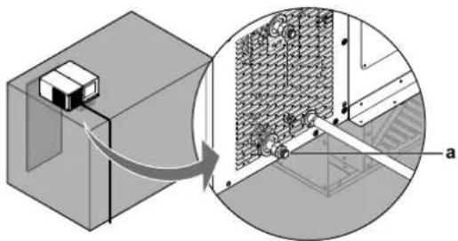
3 Reverse the flow direction every 30 minutes, if possible.
4 Replace the cleaning acid with a 1 - 2% solution of sodium hydroxide (NaOH) or sodium bicarbonate (NaHCO3) for the last rinse, to ensure that all acid has been neutralized.
5 After cleaning, rinse the heat exchanger thoroughly using clean water.
7.2 Scheduled maintenance
Periodically check wear condition of electrical contacts. If necessary have them replaced by a qualified technician.

NOTICE
NEVER service or repair the unit by yourself. Ask a qualified service person to perform this work.
Under no circumstances the user is allowed to:
- Replace electrical components.
Work on the electric equipment.
Repair mechanical parts. - Work on the refrigerating system.
Work on the control panel.
Work on protection and safety devices.
| Every 6 months | Inspection and maintenance programs |
| ● | Check the alarm list. |
| ● | Check the condenser and clean if necessary (air cooled models only). |
| ● | Check the evaporator and clean if necessary. |
| ● | Check that the drain pipe is not clogged. |
| ● | Clean the water circuit if necessary (water cooled models only). |
8 Troubleshooting
If one of the following malfunctions occurs, take the measures shown below and contact your dealer.

WARNING


Stop operation and shut OFF the power if anything unusual occurs (burning smells etc.).
Leaving the unit running under such circumstances may cause breakage, electrical shock or fire. Contact your dealer.

WARNING

If the internal wiring or the supply cable is damaged, it has to be replaced by the manufacturer, its service agent or similarly qualified persons.
The system MUST be repaired by a qualified service person.
| Malfunction | Measure |
| If a safety device such as a fuse, a breaker or an earth leakage breaker frequently actuates. | Turn OFF the main power switch. Notify your installer and report the malfunction. |
| If water leaks from the condenser side of the unit. | Stop the operation. • Check that the drain pan pipe has no leaks. • Check that the external drain pan pipe is properly connected. • Check that all the thermal insulation sponges provided with the unit are properly installed. • Check that there are no leaks in the water circuit (only for LMCEY1W+LMCEY2W). • Check that the connections of the water inlet and outlet pipes have been made properly. (only for LMCEY1W+LMCEY2W) |
| If water leaks from the drain pan under the evaporator. | Check that the drain pan pipe is not clogged. |
| The operation switch does NOT work well. | Turn OFF the power supply. |
| If the user interface display indicates an alarm. | Check section "8.1 Error codes: Overview" [22]. Notify your installer and report the error code. |
If the system does NOT operate properly except for the above mentioned cases and none of the above mentioned malfunctions is evident, investigate the system in accordance with the following procedures.
| Malfunction | Measure |
| If the system does not operate at all. | ·Check if there is no power failure. Wait until power is restored. If power failure occurs during operation, the system automatically restarts immediately after power is restored. ·Check if no fuse has blown or breaker is activated. Change the fuse or reset the breaker if necessary. ·Check if the mains cable is still connected properly. ·Check if the user interface in the remote control panel is still connected properly. |
| Malfunction | Measure |
| Unit does not start operating when pressing ON/OFF key, the display however is turned on. Notice that the compressor starts up after a pre-set delay. This function is useful to protect the compressor and the relay from power cycling in the event of repeating power outages. Defrosting (if required) also starts after this delay. | ·Check the door micro switch. The switch must be actuated and the NO contact must be closed when the door is closed. |
| Compressor stops. The unit is equipped with an overtemperature device which stops the compressor every time the max. allowable temperature of the inverter circuit board is exceeded. Possible causes are: ·Insufficient ventilation of the room where the unit is installed. ·Unit working outside the operating range. ·Anomaly in mains voltage. ·Faulty operation of condenser fan (or inverter cooling fan). Device reset is automatic after temperature dropped to normal. | ·Make sure to have installed all the metalsheet panels of the unit and check if air inlet or outlet of the un condenser is not blocked by obstacles. Remove any obstacles and make sure the air can flow freely. ·Make sure to operate in the unit operation range (see "5.1 Operation range" [17]). ·Make sure that the unit has been installed properly. Refer to "General installation guidelines" in the installation manual. ·Check power supply (voltage). Correct if necessary. ·Check operation of the condenser fan (or inverter cooling fan). If it is not working, contact your dealer. |
| The system stops immediately after starting operation. The unit is equipped with an overvoltage suppressor device for safety reasons and to protect the electrical components. | ·Check if the plug has been installed properly. Check the legend for the cable labelling in the manual and make sure to properly connect each conductor line terminal in the plug. ·Make sure that the protections applied to the electrical supply are compliant with national standards. ·If the problem persists, contact your dealer. |
8 Troubleshooting
| Malfunction | Measure |
| The system operates but cooling is insufficient. | ·Check if air inlet or outlet of the unit evaporator is not blocked by obstacles. Remove any obstacles and make sure the air can flow freely. ·Check if the evaporator inside the cold room is not frosted up. Defrost the unit manually. ·Check if there are not too many articles inside the cold room, see "5.3 Storing the goods" [▶ 18]. Do overload the cold room. ·Check if there is smooth air circulation inside the cold room. Reorganise the articles inside the cold room, see "5.3 Storing the goods"[▶ 18]. ·Check if there is not too much dust on the condenser. Remove the dust, see "7.1.2 To clean the interior" [▶ 19] clean the interior. ·Check that the water circuit is not clogged (only for LMCEY1W+LMCEY2W). ·Check that the plate heat exchanger is fed with the prescribed water mass flow (only for LMCEY1W+LMCEY2W), see "5.1 Operation range" [▶ 17]. ·Check if there is cold air leaking out of the cold room. Stop the air from leaking outside. ·Check if you did not set the temperature too high. Set the setpoint appropriately, see "4.2.3 To set the temperature" [▶ 10]. ·Check if there are no high-temperature articles stored in the cold room. Always store articles after they have cooled down. ·Check if the door is not opened too long. Reduce the opening time of the door. |
After checking all the items above, if it is impossible to fix the problem yourself, contact your installer and state the symptoms, the complete model name of the unit (with manufacturing number if possible) and the installation date.
8.1 Error codes: Overview
In case a malfunction code appears on the indoor unit user interface display, check alarm description, effect and troubleshooting. In case the alarm persist, contact your installer and inform the malfunction code, the unit type, and serial number (you can find this information on the nameplate of the unit).
For your reference, a list with malfunction codes is provided. You can, depending on the level of the malfunction code, reset the code by pushing the ON/OFF button. If not, ask your installer for advice.
The error codes are visible in the alarm menu.
To access the alarm menu and to reset an alarm or error code, see "4.5 About the alarms" [▶ 15].
| Display code | Description | Trigger | Effect | Reset | Troubleshooting |
| CE | Configuration write error. | Error in writing parameter. Unvalid values written into parameter. Unit was turned OFF while parameters writing was not finished. | Parameter not saved. Automatic | • Contact your dealer/installer. | |
| Display code | Description Trigger | Effect Reset Troubleshooting | |||
| cht | High condensing temperature warning. | Condenser may be obstructed, causing a higher temperature. | Unit continues operation. | Automatic - Check if the condenser is properly cleaned from dust and dirt. - Check if the air inlet and outlet of the unit are obstructed, causing a reduction of airflow to the condenser. - Check that the water circuit is not clogged (only for LMCEY1W+LMCEY2W). - Check that the plate heat exchanger is fed with the prescribed water mass flow (only for LMCEY1W+LMCEY2W).see "5.1 Operation range" [▶ 17]. - Check if the unit is working within the temperature range prescribed into the manual. See "5.1 Operation range" [▶ 17]. - If the problem persists contact your dealer/installer. | |
| dor | Door open. Door has been opened and the door switch is active. | Unit operation stops. Automatic when door is closed. | - Close the cold room's door. - If the warning persists when the door is closed, check if in this condition microswitch is correctly actuated. - If the problem persists Contact your dealer/installer. | ||
| E1 | Th3 suction air prove error. | Th3 faulty or disconnected. | Unit continues operation with backup Th5 thermistor control, with +10°C offset. | Automatic - Contact your dealer/installer. | |
| E2 | Th5 Eva inlet prove error. | Th5 faulty or disconnected. | Unit stops operation except the evaporator fan. | Automatic - Contact your dealer/installer. | |
| E3 | Th6 Eva outlet prove error. | Th6 faulty or disconnected. | Unit stops operation except the evaporator fan. | Automatic - Contact your dealer/installer. | |
| E4 | Th1 Discharge prove error. | Th1 faulty or disconnected. | Unit stops operation except the evaporator fan. | Automatic - Contact your dealer/installer. | |
| E6 | Th7 Discharge prove error. | Th7 faulty or disconnected. | Unit stops operation except the evaporator fan. | Automatic - Contact your dealer/installer. | |
| Ed1 | Defrost terminated after maximum time. | Defrost on evaporator 1 ended by defrost timeout dP1. | Defrost ends, nomral operation starts. | Defrost ends and unit continues operation. | - Check if the evaporator is properly cleaned from ice or dirt. - Avoid to Open the cold room door for a minimum of 4 hours to avoid moisture and ice, and allow the unit to perform another defrost. - If the problem persists contact your dealer/installer. |
| Etc | Real time clock error (not set or not updated). | Real time clock not updated. | Unit continues operation but timer operations like the scheduler will not work. | Automatic | - Set Real Time Clock from Daikin Apps: Setting/Device/Set data/time. - If the problem persists contact your dealer/installer. |
8 Troubleshooting
| Display code | Description Trigger | Effect Reset Troubleshooting | ||||
| HA | Type HA HACCP alarm (high temp. during operation): High temperature limit set by user for HACCP has been reached inside the cold room. | High temperature limit reached. | Unit continues operation at maximum compressor speed. | Automatic | ·Check if the door of the cold room closes adequately, avoiding outside air to enter into the cold room. ·After the warning, check if the temperature of the cold room is dropping. ·Check if Parameters AH and Htd are coherent with the set point. See "5.4 HACCP alarms" [▶ 18]. ·If the problem persists contact your dealer/installer | |
| HF | Type HF HACCP alarm (high temp. after blackout): High temperature limit set by user for HACCP has been reached inside the cold room after a blackout. | High temperature limit reached. | Unit continues operation at maximum compressor speed. | Automatic · Contact your installer to check if the unit has power supply and to check the causes of blackout. ·Check if the door of the cold room closes adequately, avoiding outside air to enter into the cold room. ·Check if the cold room temperature is dropping. ·Check if Parameters AH and Htd are coherent with the set point. See "5.4 HACCP alarms" [▶ 18]. ·If the problem persists contact your dealer/installer. | ||
| HI High | temperature limit has been reached inside the cold room. | High temperature limit reached. | Unit continues operation at maximum compressor speed. | Automatic | ·Check if the door of the cold room closes adequately, avoiding outside air to enter into the cold room. ·Check if the cold room temperature is dropping. ·Check if Parameter AH is coherent with the set point. See "4.3 Configuration" [▶ 11]. ·If the problem persists contact your dealer/installer. | |
| IA | High pressure error. | HPS has been activated. | Unit stops operation. | Automatic reset after 10 minutes or manually. | ·Check if the condenser is properly cleaned from dust and dirt. ·Check if the air inlet and outlet of the unit are obstructed, causing a reduction of airflow to the condenser. ·Check that the water circuit is not clogged (only for LMCEY1W+LMCEY2W). ·Check that the plate heat exchanger is fed with the prescribed water mass flow (only for LMCEY1W+LMCEY2W).see "5.1 Operation range" [▶ 17]. ·Check if the unit is working within the temperature range prescribed into the manual. See "5.1 Operation range" [▶ 17]. ·If the problem persists contact your dealer/installer. | |
| LO | Low temperature limit has been reached inside the cold room. | Low temperature limit reached. | Unit stops operation except the evaporator fan. | Automatic | ·Open the cold room door to allow the temperature to raise up. ·Check if the cold room temperature is raising up. ·Check if Parameter AL is coherent with the set point. See "4.3 Configuration" [▶ 11]. ·If the problem persists contact your dealer/installer. | |
| Display code | Description Trigger | Effect Reset Troubleshooting | ||||
| SF | Configuration not completed correctly. | Incorrect numerical setting in parameter file. Not assigned the required functions. For example, when the set value is outside the allowable range. | Parameter not saved. | Automatic - Exit from the parameters section. • Restart the unit power supply. • If the problem persists contact your dealer/installer. | ||
| CHt High condensing temperature alarm. | High temperature limit reached at condenser. | Unit stops operation except the evaporator fan. | Manual | • Check the cleaning condition of the condenser. • Avoid obstructing the condenser. • Check that the water circuit is not clogged (only for LMCEY1W+LMCEY2W). • Check that the plate heat exchanger is fed with the prescribed water mass flow (only for LMCEY1W+LMCEY2W), see "5.1 Operation range" [▶ 17]. • Check if the unit is working within the operative temperature range. See "5.1 Operation range" [▶ 17]. • If the problem persists Contact your dealer/installer. | ||
| Hdt | High discharge temperature. | High Discharge Temperature limit reached. | Unit stops operation. | Manual | • Check the cleaning condition of the condenser. • Avoid obstructing the condenser. • Check that the water circuit is not clogged (only for LMCEY1W+LMCEY2W). • Check that the plate heat exchanger is fed with the prescribed water mass flow (only for LMCEY1W+LMCEY2W), see "5.1 Operation range" [▶ 17]. • Check if the unit is working between the operative temperature range. See "5.1 Operation range" [▶ 17]. • If the problem persists Contact your dealer/installer. | |
| Parent-child connection units | ||||||
| Display code | Description | Trigger | Effect | Reset | Troubleshooting | |
| MA | Main secondary offline. | Main error and communication error on the secondary unit (displayed on the slave unit). | Depends on parent-child connection settings and error content. | Automatic • Contact your installer to check if the slave units have power supply. • Check Alarms of secondary units. • If the problem persists contact your dealer/installer. • Restart the units. | ||
| u1~u4 | Main secondary offline (HMI display is u*). | Main error and communication error of Secondary machine (display of master machine). | Depends on parent-child connection settings and error content. | Automatic • Contact your installer to check if the slave units have power supply. • Check Alarms of secondary units. • If the problem persists contact your dealer/installer. • Restart the units. | ||
| n1~n4 | There is an alarm related to one of the secondary units. | HMI display on the master unit. Child action depends on the type of alarm. | Depends on parent-child connection settings and error content. | Automatic | • Check Alarms on the HMI of secondary units. • If the problem persists contact your dealer/installer. • Restart the units. | |
| Av1~Av4 | Main and secondary software are different. | Alarm firmware not compatible on Secondary 1...4 (only on Main). | Parent/child connection can't be set. | Automatic • Contact your dealer/installer. | ||
9 Disposal
| Display code | Description Trigger | Effect Reset Troubleshooting | |||
| Only double circuit units | |||||
| Display code | Description Trigger | Effect Reset Troubleshooting | |||
| Ed2 | Defrost on second evaporator terminated after maximum time. | Defrost on evaporator 2 ended by defrost timeout dP2. | Defrost ends, nominal operation starts. | Defrost ends and unit continues operation. | Check if the evaporator is properly cleaned from ice or dirt.Avoid to open the cold room door for a minimum of 4 hours to avoid moisture and ice, and allow the unit to perform another defrost.If the problem persists contact your dealer/installer. |
| E7 Th1 | 2 discharge circuit 2 prove error. | Th12 faulty or disconnected. | Unit stops operation except the evaporator fan. | Automatic - Contact your dealer/installer. | |
| E8 | Th72 discharge circuit 2 prove error. | Th72 faulty or disconnected. | Unit stops operation except the evaporator fan. | Automatic - Contact your dealer/installer. | |
| dA1 | Th52 circuit 2 Eva inlet prove error. | Th52 faulty or disconnected. | Unit stops operation except the evaporator fan. | Automatic - Contact your dealer/installer. | |
| dA2 | Th62 circuit 2 Eva outlet prove error. | Th62 faulty or disconnected. | Unit stops operation except the evaporator fan. | Automatic - Contact your dealer/installer. | |
| EdcB | EVDmin offline. Commu nication error between ACU and EVDmin (dEd = Alarm at 1440min delay, product stopped). | Unit stops operation except the evaporator fan. | Automatic | Try, if possible, to restart the unit power.If the problem persist contact your dealer/installer.Check if the unit is working within the operative temperature range. See "5.1 Operation range" [▶17]. | |
| EE | EEPROM Malfunctioning. | EEPROM operating and/or unit parameters damaged. | Total shutdown. | Replace the driver. Contact service. | Contact your dealer/installer. |
9 Disposal
During normal operation of the unit, no substances arise that need to be disposed of in a special way.
Wooden, plastic and polystyrene packing must be disposed of according to the regulations in force in the country where the unit is used.

NOTICE
Do NOT try to dismantle the system yourself: dismantling of the system, treatment of the refrigerant, oil and other parts MUST comply with applicable legislation.
Final disposal of the unit must be done by an authorised area technical assistance service, that has proper training, equipment and instructions for the dismantling. They are also responsible for reuse, recycling and recovery.
- Units are marked with the following symbol:
This means that electrical and electronic products may NOT be mixed with unsorted household waste. Do NOT try to dismantle the system yourself: dismantling the system, treatment of the refrigerant, of oil and of other parts MUST be done by an authorised installer and MUST comply with applicable legislation.
Units MUST be treated at a specialised treatment facility for reuse, recycling and recovery. By ensuring this product is disposed of correctly, you will help to prevent potential negative consequences for the environment and human health. For more information, contact your installer or local authority.

CAUTION

There are potential environmental hazards involved in dismantling the unit.
10 Glossary
Accessories
Labels, manuals, information sheets and equipment that are delivered with the product and that need to be installed according to the instructions in the accompanying documentation.
Applicable legislation
All international, European, national and local directives, laws, regulations and/or codes that are relevant and applicable for a certain product or domain.
Authorised installer
Technical skilled person who is qualified to install the product.
Dealer
Sales distributor for the product.
Field supply
Equipment NOT made by Daikin that can be combined with the product according to the instructions in the accompanying documentation.
Installation manual
Instruction manual specified for a certain product or application, explaining how to install, configure and maintain it.
Maintenance instructions
Instruction manual specified for a certain product or application, which explains (if relevant) how to install, configure, operate and/or maintain the product or application.
Operation manual
Instruction manual specified for a certain product or application, explaining how to operate it.
Optional equipment
Equipment made or approved by Daikin that can be combined with the product according to the instructions in the accompanying documentation.
Service company
Qualified company which can perform or coordinate the required service to the product.
User
Person who is owner of the product and/or operates the product.
Inhaltsverzeichnis
GEFAHR: STROMSCHLAGGEFAHR
| LMCEY1A13AVM01 | LMCEY2A19+25AYE01 |
GEFAHR:STROMSCHLAGGEFAHR
7.2 Maintenance programme 77
8 Dépannage 77
| LMCEY1A13AVM01 | LMCEY2A19+25AYE01 |
7.2 Maintenance programme
WAARSCHUWING: ONTVLAMBAAR MATERIAL


Koolstofdioxidevergifting.
- Verstikking.
Brand.

WAARSCHUWING


| LMCEY1A13AVM01 | LMCEY2A19+25AYE01 |
| LMCEY1W12AVM01 | LMCEY2W19+25AYE01 |
| Model | Capaciteit Aantal koelcircuits | Koelstand |
| LMCEY1A13AVM01 | 1,26 kW(a) | 1 Luchtgekoeld |
| LMCEY2A19AYE01 | 1,98 kW(a) | 2 Luchtgekoeld |
| LMCEY2A25AYE01 | 2,57 kW(a) | 2 Luchtgekoeld |
| LMCEY1W12AVM01 | 1,23 kW(b) | 1 Watergekoeld (c) |
| LMCEY2W19AYE01 | 1,96 kW(b) | 2 Watergekoeld (d) |
| LMCEY2W25AYE01 | 2,60 kW(b) | 2 Watergekoeld (e) |
a Knop OMHOOG
b. Knop OMLAAG
c. Knon PROGRAMMA
CtL Regelmenu
Pro Sondemenu weergeven
HcP HACCP-menu
CnF Configuratiemenu
ALM Alarmmenu
PSd Onderhoudsmenu
ESC Menulus verlaten
a Knop OMHOOG
b Knop OMLAAG
c Knop PROGRAMMA

INFORMATIE
| LMCEY1A13AVM01 | LMCEY2A19+25AYE01 |
| LMCEY1A13AVM01 | LMCEY2A19+25AYE01 |
| LMCEY1W12AVM01 LMCEY2W19+25AYE01 | |
Wi-Fi uBOSS (wireless, 3MCB002ACC)
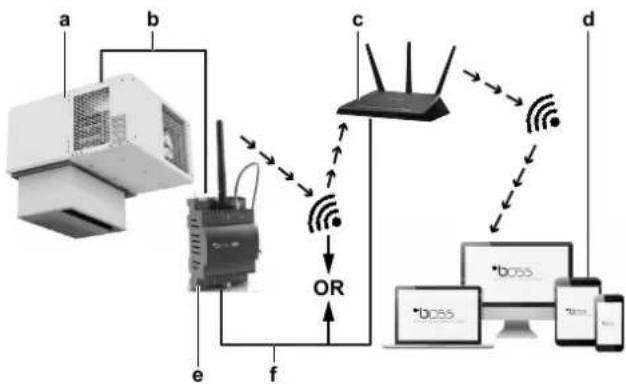
Da repertoire in loco
| LMCEY1A13AVM01 | LMCEY2A19+25AYE01 |
Aaayn n ageans aeitoupyias:
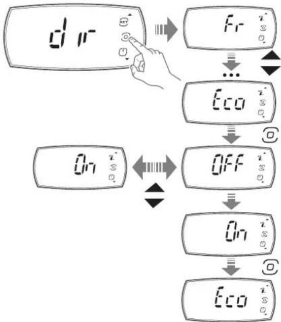
3 Pntote to koupti PROGRAM otny oovn "dir".
Anotetaeqa: Tyn oovn eapaviectai n npwn aueon aeioupvia (n.x. "Fr").
4XpoiioTIOIATE ta kouptia UP kaDOWN ia TlAorinyon oTo μevou.
5 Pntote to koupti IPOPTPAMMA oIs pTaOeTe Otv 08ovn aegc lteuupyia cTou oEeTe va aaaleTe (T.x."Eco").
Anotelaeqa: Eiaayayate nvy aean aeitoupyia.
6 Nahtote ta kouptia UP kai DOWN via va aaladet n puthetaion (π.x. aalayn σ "On").
7 Nnntote to koupti PROGRAM yia va etiiebaiaoe t n vao pueuion.
AnotEaOma: H oovn eavepxetai otny oovn aoeans Aetoupyias (π.x."Eco").
8 XpnoiIOIOHOTa KOUPTIAUPKAI DOWNYIA TAnOynon OTo
meVou.KAVTE KUION OTNVEIeovn AeOn AeIToupyia TcS OTIoAs
TNV KAtdOtaON ΘEETe va aAALAE.
Molis TEAEIOOETe TIV aALayn TNS KATaON Tov aoeow Aetoupyiiv:
9 KáVTE KúλIσn ΜτNv OθOvN "ESC".
10 Ntnto To koupti PROGRAM.
AnotEaouo: O oovn EtniTppeei otyn oovn aeeonc evpyoioinoc nvepyoioint/AAeoupyiac (ddir).
Autn katnyopia Tepiaaabeovayepouc yia touoou to
pei eiaopppwetai wc ouvayepuoc, opalata aioehtnpw
ouvayepuoCtepkoqaoias, k.lT.

IIAHPOΦOPIE
O BoBnTc 8a EvpyToIEiTa otav utapxE Evpyoc
5.3 AToθκεuσn Tov TpoiovTov

EIAONOIHEN
Mny kalutte Ta aoiyuata Eoiaywyns kai esaywyns aepa npoc tov ouuukwnt kai tov esatuiotn Tns movadas.
H diatnpnon ts oswths Eepokpaiaas Eaopaiaic t hi diatnpnon ts troiotaTsw atothekeuevuv Tpoivuw.
H kukloopopia tou aepa exi trolu eeyaln onpaia yia th diatnpno oouioopopns 0epuokpaaic as oakpano tv uuktko taalmo. H avetapknc kukloopopia aepa mtopei va tpokaoleoi tv oxmaioo 0ulakw vepotntac n layou.
Tia auToV tov loyo:
Na xnpoiotoeite TaTeC npapia Tou dieukouvouv Tny Kukloopopia tou aepa katw atto Ta tpoiovta.
- Na toTOnoTeEite Ta TPOIOvTa paKpia atTo Ta ToiXwMa ta Tou yukTKOu BaIauou. Eav xpeiaZeTai, va xpoioJIoTEe aTOOTATEc.
ApoTe Xwpo Tepiou 20 cm mEaTu wv TpoivwV kai Tns opoqnc Tou uuktkou thalou.
Στοβαζετa Tpoiδvta Tou Tapayouv θερμόnteta, oTiwcs Ta φροúta kai ta λayaviká, kata τetioiv TpoTTo wote va δημιουργeītai apketos χωpos γia tny aTOnμákpuvon Tns TAPAYOEvns θερμóntaσ μεω nTs Kukloφoplaç Tou Kpuou aepa.
Na 0toiBaZeTE TPOIOVTA TOU SEVPaayouv EepoNTa,OTWc TO Kpeac kai KATEUUYEVA TPOIOVTA,OE PIKn aTODaON METAuTOUC OTo Kevtpo Tou yukTKOu BAaApou.
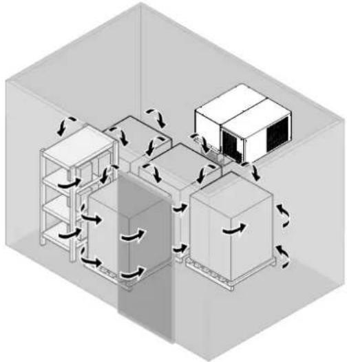

IPOEIAOIOIHSH
H Daikin ev eval uTeuovn yia tv aopala taou uukTKOUaIauou.
Bepaiweite oT dev npapevouv atopa stov yuktiok 0a aipo npiv kaeiote Tt tiopcs:
Kivduos aopuigac. Tov uuktko 0daaio TpeTei va Taapaevei kevoc xwpo8 12 m3
Kivduos Kpuotaymuatoc.
Kivduvoosavatou Aoyw TAYETOU.
5.4 EuvaepoHACCP
Aut n movada napexetai eT n aeitoupyia eEyxou HACCP. To HACCP (Avauon kivduvou kai kpiio o npelio eEyxou) evai eva ouotma diaeipianr tou exei oxediaotei ia va avaywpicei kivduvoucs iyn uyeia kai va epapaoctoi patayikc yia tvn atotpontn, tny ealeiyn n tn meiwn ts eupdviiontousc.
H leitoupyia eeyxou HACCP Tou elvai evomegaatwveyn oe autytn movada eintipente Tov eeyxo kai Tnv npakolouon Tou kpiaiou onneiou eeyxou (Bepuokpaa ius).
Eivai eTlncsduatn n hyn avapopov tou kataekvouv tn oumuoppwn Tnv tpexoua vopoia.
XpnoiopoTioWvTac Tny Eapuoyn Daikin, elva duvat n EvepyoToinon Tns Eyypaipns 6ebouevuv HACCP on nuovda aalacovTac Tny Tnpaupetpo "Htd". Deite Tnv Evotnta "4.3 Diaopopwn" [▶181].
H apxikpuoi nTn Tnapaepou "Htd" evai 0", kati Tou onpaivei ot i eyyapn doeovv HACCP evai attevepyoioeyn.
| LMCEY1A13AVM01 | LMCEY2A19+25AYE01 |
Luz da-camera frigorifica (1KIT862ACC)
Se as circunstancias o permittirem:
- General safety precautions 2
- About the unit and options 6
- User interface 9
- Operation 17
- Energy saving and optimum operation 19
- Maintenance and service 19
- Troubleshooting 20
- Disposal 26
- About this document
- Target audience
- Documentation set
- - Installation manual:
- Operation manual:
- Technical engineering data
- General safety precautions
- About the documentation
- Meaning of warnings and symbols
- For the user
- General
- INFORMATION
- WARNING
- For storage:
- WARNING: FLAMMABLE MATERIAL
- Stop operation and shut OFF the power if anything unusual occurs (burning smells etc.).
- CAUTION
- Disclaimer
- Refrigerant
- DANGER
- Electrical
- DANGER: RISK OF ELECTROCUTION
- About the unit and options
- About the system
- About the different models
- Safety systems
- Safety symbols location
- Possible options for the unit
- NOTICE
- Door switch (3MCT014ACC)
- Door heater
- Cell light (1KIT862ACC)
- Alarm
- Router
- Combining multiple units
- User interface
- Overview
- Meaning of signals that appear on the display
- Basic functions
- To unlock the user interface
- To start up
- To set the temperature
- To shut down
- To navigate between screens
- To change the status of an actuator
- To change the status of a direct function
- Configuration
- To connect your device with Daikin User
- To save the factory parameters
- To change the parameters
- To set the shared functions for multiple units
- Lights
- Door open
- Network temperature regulation
- Network defrost
- About the alarms
- To enter the alarm screen
- 4Userinterface
- About types of malfunctions
- Take into account that:
- To reset an alarm or warning
- About the alarm log
- Alarm log
- Operation
- Operation range
- Operation procedure
- Storing the goods
- HACCP alarms
- Specific alarms
- Energy saving and optimum operation
- Always:
- Maintenance and service
- Cleaning the unit
- To clean the exterior
- To clean the interior
- Condenser heat exchanger cleaning
- Evaporator heat exchanger cleaning
- To clean the water circuit
- Scheduled maintenance
- Troubleshooting
- Error codes: Overview
- Disposal
- Glossary
- Accessories
- Applicable legislation
- Authorised installer
- Dealer
- Field supply
- Installation manual
- Maintenance instructions
- Operation manual
- Optional equipment
- Service company
- User
- Inhaltsverzeichnis
- GEFAHR: STROMSCHLAGGEFAHR
- GEFAHR:STROMSCHLAGGEFAHR
- Dépannage 77
- Maintenance programme
- WAARSCHUWING: ONTVLAMBAAR MATERIAL
- WAARSCHUWING
- INFORMATIE
- Wi-Fi uBOSS (wireless, 3MCB002ACC)
- Da repertoire in loco
- IIAHPOΦOPIE
- AToθκεuσn Tov TpoiovTov
- EIAONOIHEN
- IPOEIAOIOIHSH
- EuvaepoHACCP
- Luz da-camera frigorifica (1KIT862ACC)
Brand : DAIKIN
Model : LMCEY1W12AVM01
Category : Air-conditioner