C.A 755 - Measuring equipment CHAUVIN ARNOUX - Free user manual and instructions
Find the device manual for free C.A 755 CHAUVIN ARNOUX in PDF.
Download the instructions for your Measuring equipment in PDF format for free! Find your manual C.A 755 - CHAUVIN ARNOUX and take your electronic device back in hand. On this page are published all the documents necessary for the use of your device. C.A 755 by CHAUVIN ARNOUX.
USER MANUAL C.A 755 CHAUVIN ARNOUX
This instrument is compliant with safety standard IEC 61010- 2-030, and the leads are compliant with IEC 61010-031, for voltages up to 600V in measurement category III. Failure to observe the safety instructions may result in electric shock, re, explosion, and destruction of the instrument and of the installations. The operator and/or the responsible authority must carefully read and clearly understand the various precautions to be taken in use. Sound knowledge and a keen awareness of electrical hazards are essential when using this instrument. Do not use your instrument on networks of which the voltage or category exceeds those stated. Do not use the instrument if it seems to be damaged, incomplete, or poorly closed. Do not use the instrument in an explosive atmosphere or in the presence of ammable gases or vapours. Before each use, check the condition of the insulation on the leads, housing, and accessories. Any item of which the insulation is deteriorated (even partially) must be set aside for repair or scrapping. Use only the leads and accessories supplied. The use of leads (or accessories) of a lower voltage rating or category limits the use of the combined instrument + leads (or acces- sories) to the lowest category and service voltage. Use personal protection equipment systematically. When handling the instrument and test probes, keep your ngers behind the physical guard. All troubleshooting and metrological checks must be done by competent, accredited personnel.16 CONTENTS
1.1. DELIVERY CONDITION C.A 755 digital tester Delivered in a cardboard box with: one red test probe 2 mm in diameter, a black lead terminated by a removable black probe tip 2mm in diameter, two alkaline batteries (AAA or LR3), one user’s manual in ve languages, a test certicate.
1.2. ACCESSORIES AND SPARE PARTS
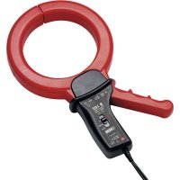
Test probes 2mm in diameter and 4mm long (one red and one black) 600V CAT III (Figure 3) Test probes 2mm in diameter and 15mm long (one red and one black) 300V CAT II (Figure 4) Test probes 4mm in diameter and 19mm long (one red and one black) 300V CAT II (Figure 5) Carrying bag LR3 or AAA batteries C.A 753 2P+T adapter. For the accessories and spares, consult our web site: www.chauvin-arnoux.com
1.3. INSERTING THE BATTERIES
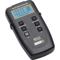
Use a screwdriver to unscrew the battery compartment cap (Figure 1). Insert the two batteries provided (AAA or LR3 1.5V alkaline batteries) (Figure 2). Screw the battery compartment cap all the way back in and make sure that it is completely and correctly closed.18 Removable black probe. Removable red probe. Backlit LCD display unit. Battery compartment cap. Key Select.
1.4. VIEW OF THE C.A 755
+ terminal. Guards. Four-position rotary switch. COM terminal. Lead terminated by a probe tip holder. 600 VCAT III1000 V max
1.5. BACK When the instrument is not being used, the probe tips can be stored on the back of the instrument (Figure 9). You can also wrap the lead around the instrument (Figure 10).19
This instrument is a digital tester. It measures AC and DC voltages, resistances, and capacitances. It also has a conti- nuity function and a diode function and can be used for non contact voltage detection. 2.1. INSTRUMENT TEST Before making any measurements, test all of the functions of the instrument. To switch the instrument on, turn the switch to any position. All segments of the display unit light (Figure 6) and the instrument emits a continuous beep. If the battery voltage is too low for correct operation of the instrument, the symbol is displayed. If the battery voltage is much too low, the display unit will not light. In both cases, it is time to replace the batteries (see § 4.2). With the inputs disconnected, set the switch to W. The display unit indicates - - - -. Connect the red probe tip to the + terminal and the black probe tip to the COM terminal. Bring the two probe tips together, so that they touch. The instrument indicates a resistance near zero and emits a continuous beep. Set the switch to V and measure a known voltage. If the results of these four tests are correct, your instrument is ready for use. 2.2. VOLTAGE Connect the red probe tip to the + terminal and the black probe tip to the COM terminal. Set the switch to V. Keep your hands behind the guards of the device and of the test probe (Figure 9). Place the test probes on the element to be tested and maintain a rm contact. The voltage is displayed (Figure 7). If the voltage is > 30V, the instrument displays , indicating that the voltage is dangerous. As default, the instrument is in automatic mode ( SCAN ). If the voltage is AC, the instrument displays AC. If the voltage is DC, it indicates DC and displays its polarity. The Select key is used to exit from the automatic mode (the SCAN symbol disappears) and display the AC voltage only, or the DC voltage only, or to return to the automatic mode. To determine the type of voltage (AC or DC) for a measure- ment < 1V, exit from the automatic mode. Do not use the C.A 755 to check for the absence of a voltage. For that, use a VAT.20
2.3. RESISTANCE, CONTINUITY, DIODE AND
CAPACITANCE Connect the red probe tip to the + terminal and the black probe tip to the COM terminal. Set the switch to W. Keep your hands behind the guards of the device and of the test probe. Place the test probes on the element to be tested (Figure 12). If a voltage is present, the instrument so indicates. Do not make a resistance, diode, continuity, or capac- itance measurement on a live circuit. As default, the instrument is in automatic mode ( SCAN ) and chooses automatically among the resistance , continui- ty , diode , and capacitance functions. To force one of these functions, press the Select key (the SCAN
symbol disappears). Resistance and continuity If the resistance is less than 300 W, the instrument is in con- tinuity (Figure 11). Below 30 W, it emits a continuous beep. Between 300 W and 3 MW, the instrument is in resistance mode. Above 3 MW, the display unit indicates OL. The 30 MW range is not available in automatic mode; resistance mode must be used. Diode In diode test, place the red probe tip on the anode of the diode to be tested and the black probe tip on the cathode. The instrument indicates the voltage of the diode. If it is above 2V or if the polarity is reversed, the instrument displays - - - -. Capacitance The 3mF and 30mF ranges are not available in automatic mode; capacitance mode must be used. If the device displays dis.C after a measurement, wait for the end of automatic discharging of the capacitance before making another measurement.
2.4. NON-CONTACT VOLTAGE DETECTION
(NCV) The instrument can detect an AC voltage of approximately 230V. Withdraw the probe tips. Set the switch to NCV. Move the top of the instrument (+ terminal side) close to the conductor without touching it. The position of the instrument may affect the result. The sensitivity is better on the battery compartment cap side (Figure 15). If no alternating voltage is detected, the device displays EF.21 If a voltage is detected, the device displays one of 4 detec- tion levels: - , the buzzer beeps once a second and the backlighting ashes at the same rate. - - , the buzzer beeps twice a second and the backlighting ashes at the same rate. - - - , the buzzer beeps three times a second and the backlighting ashes at the same rate. - - - -, the buzzer emits a continuous beep and the back- lighting is on continuously.
The absence of a voltage indication in the NCV func- tion does not mean that there is no voltage. To conrm the absence of a voltage, use a VAT. 2.5. AUTOMATIC STANDBY To save the batteries, the instrument automatically switches to standby after 10 minutes without user activity (switch turned or Select key pressed). The instrument can be reactivated by turning the switch or pressing the Select key.
3.1. REFERENCE CONDITIONS Quantity of inuence Reference values Temperature 23 ± 5 °C Relative humidity 30 to 75% RH Supply voltage 3 ± 0.1V Frequency of the measured signal DC or 45 to 65Hz Type of signal sinusoidal External electric eld < 1V/m DC external magnetic eld < 40A/m 3.2. ELECTRICAL CHARACTERISTICS
Particular reference conditions: AC signal ≤ 1% in DC measurements. DC signal ≤ 1% in AC measurements.22 Range 3 V 30 V 300 V 1000 V Measurement range 3 mVdc to 2,999 Vdc
to299.9 V 300 V to 1000 V 100 mVac to 2,999 Vac Resolution 1 mV 10 mV 100 mV 1 V Intrinsic uncertainty in Vdc 2% ± 3 pt Intrinsic uncertainty in Vac 3% ± 4 pt Input resistance 10 MW Automatic AC/DC detection is possible only above 450 ± 150mV.
Resolution 0,1 W 1 W 10 W 100 W 1 kW 10 kW Intrinsic uncertainty 3% ± 5 pt 3% ± 3 pt 5% ± 3 pt The 30 MW range is not available in automatic mode. In continuity, in the 300 W, range, the instrument emits an audible signal below 30 W.
Particular reference conditions: Zero voltage. Diode without resistance or capacitance in parallel. Diode voltage measured between 0.29 and 2V.
Particular reference conditions: Zero voltage. Capacitance without resistance in parallel. Range 3 nF * 30 nF * 300 nF 3 µF Measurement range 400 pF to
The instrument detects the line voltage at 230VAC with respect to ground, at 50 Hz and at a distance of less than 5cm. 3.3. ENVIRONMENTAL CONDITIONS Operating range: -10°C at 55°C and ≤ 80%RH without condensation up to 40° C. Storage range (without battery): -20°C at +55°C and ≤ 90%RH without condensation up to 45°C. If an extended period of non-use is anticipated, or for storage, withdraw the batteries from the housing. For use indoors and outdoors without rain. Pollution degree: 2. Altitude: <2000m. 3.4. POWER SUPPLY The instrument is powered by two 1.5V alkaline batteries (type AAA or LR3). Battery life is 100 h.
3.5. CHARACTERISTICS OF CONSTRUCTION
Dimensions (L x W x D) 180 x 52 x 45 mm Mass 200 g approx. Cable length 142 cm Protection rating IP 54 according to IEC 60529 IK 04 according to IEC 50102 Drop test 2 m. 3.6. ELECTRICAL SAFETY Electrical safety 600 V CAT III per IEC 61010-1, IEC 61010- 031 and IEC 61010-2-030. 3.7. ELECTROMAGNETIC COMPATIBILITY Emission and immunity in industrial environment according to IEC 61326-1.24
Except for the batteries, the instrument contains no parts that can be replaced by personnel who have not been specially trained and accredited. Any unauthor- ized repair or replacement of a part by an “equivalent” may gravely impair safety. 4.1. CLEANING Disconnect the instrument completely. Use a soft cloth, dampened with soapy water. Rinse with a damp cloth and dry rapidly with a dry cloth or forced air. Do not use alcohol, solvents, or hydrocarbons.
4.2. REPLACEMENT OF BATTERIES
If the symbol is displayed during a measurement, you must replace the batteries. Disconnect the instrument completely. Refer to §1.3 for the replacement of the batteries. Spent batteries must not be treated as ordinary house- hold waste. Take them to the appropriate recycling collection point.