C.A 7028 - Measuring equipment CHAUVIN ARNOUX - Free user manual and instructions
Find the device manual for free C.A 7028 CHAUVIN ARNOUX in PDF.
Download the instructions for your Measuring equipment in PDF format for free! Find your manual C.A 7028 - CHAUVIN ARNOUX and take your electronic device back in hand. On this page are published all the documents necessary for the use of your device. C.A 7028 by CHAUVIN ARNOUX.
USER MANUAL C.A 7028 CHAUVIN ARNOUX
1.1 Receiving Your Shipment
Upon receiving your shipment, make sure that the contents are consistent with the packing list. Notify your distributor of any missing items. If the equipment appears to be damaged, file a claim immediately with the carrier and notify your distributor at once, giving a detailed description of any damage. Save the damaged packing container to substantiate your claim. Caution ! if you ship this instrument on elsewhere, use preferably the original packaging and indicate the reasons for reshipment as clearly as possible in a note enclosed with the equipement. Note : our products are patented in France and Abroad. Our logos are registrered trade marks. E reserved the right to modify the characteristics and prices should technological advances make it necessary.
1.2 Ordering Information
Wire Mapper Pro™ Model CA7028 .................................................................. P01129501 Includes meter, carrying case, remote ID (#1), 2 patch cords, 4 x 1.5 AA batteries, user manual and a product warranty card.
1.2.1 Accessories and Replacement Parts:
International Electrical Symbols This symbol signifies that the instrument is protected by double or reinforced insulation. Use only specified replacement parts when servicing the instrument. This symbol on the instrument indicates a WARNING and that the operator must refer to the user manual for instructions before operating the instrument. In this manual, the symbol preceding instructions indicates that if the instructions are not followed, bodily injury, installation/sample and product damage may result. Risk of electric shock. The voltage at the parts marked with this symbol may be dangerous. WARNING n This instrument meets the safety requirements of IEC61010-1:1995. n The Model CA7028 is designed for use on de-energized circuits only. n Connection to line voltages will damage the instrument and could be hazardous to the operator. n This instrument is protected against connection to telecom network voltages according to EN61326-1. n Safety is the responsibility of the operator.2928
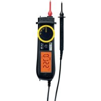
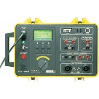
The Wire Mapper Pro™ is a hand-held structured cable tester and troubleshooter designed for use on UTP, STP, FTP & SSTP cabling equipped with RJ45 connectors and wired to either TIA 568A/B (ISO11801 & EN50137), USOC or ISDN specifications. It detects open circuit pairs, shorts, crossed wires, crossed pairs, reversed pairs, shield faults and split pairs. In the event of opens and shorts, the Wire Mapper Pro™ uses TDR technology to indicate if the fault is at the near end of the cable, the remote end, or if it is somewhere in between. It will then indicate the distance to the fault. The Wire Mapper Pro™ has the ability to measure and indicate the length of the cable under test, using a Vp (Velocity of Propagation), set by the user. It will measure and report the length of all 4 pairs of wires in the cable under test. It also generates an audible tone that is transmitted into all 4 pairs on the cable under test. This can be used for cable tracing and identification. This instrument also has the ability to identify telephone and data lines. If the main unit is plugged into an operational RJ45 socket, it will give a continuous warning tone and appropriate display if a telephone voltage is present on any of the pins. If the Service Detect key is pressed, it will give a display distinguishing 10base-T, Token Ring and 100Mbit+ connections. Features: n Hand-held cable and troubleshooting tester n Designed for use on UTP, STP, FTP & SSTP cabling equipped with RJ45 connectors and wired to either TIA568A/B (ISO11801 & EN50137), USOC or ISDN specifications. n Detects open circuit pair, shorts, crossed wires, crossed pairs, reversed pairs, shield faults and split pairs. n Indicates location of the fault n Measures and indicates the length of the cable under test n Emits an audible tone, used to trace a cable and identify the type of fault n Identifies telephone and data lines n Up to 16 Remote IDs identified3130 Remote Dimensions: 2.5 x 2.0 x 1.0" (65 x 52 x 25mm) Safety: IEC61010-1
CE: Compliant with current EU directives
Range: 500 ft (150m) Accuracy: ±5% Cable Types: UTP, STP, FTP & SSTP Faults Indicated: Short Circuit Pair Open Circuit Wire Short Between Pairs Split / Cross Pairs Pair Reversals Shield Continuity Fault Location: Near End, Remote End, or distance if midway Wiring Schemes: TIA 568A/B, USOC & ISDN Service Indication: Telephone, 10BaseT, 100Mbit+, Token Ring Voltage Warning: Warns of TNV (Telecom Network Voltage) presence Test Inhibit: Inhibits Testing in the presence of live voltages Tone Generator: Tone generator (oscillating) 810Hz - 1110Hz Battery indicator: 0 to 100% "Gas Gauge" Bargraph Main Unit Display: 128 x 64 pixel Graphical LCD Fault Display: All fault and setting info displayed textually and graphically Display Backlight: Electroluminescent Remote Display: Green/Red LED Languages: English (USA and UK), German, French, Spanish, Italian Power Supply: 4 x 1.5V AA alkaline batteries Auto Power Off: after 3 minutes Battery Life: Standby mode >4000hrs Continuous testing >7.5hrs Storage Temperature: -4 to 158°F (-20 to 70°C) 5 to 95% RH non-condensing Operating Temperature: 32 to 112°F (0 to 40°C) 5 to 95% RH non-condensing Main Unit Weight: 12 oz (350g) Main Unit Dimensions: 6.5 x 3.5 x 1.5" (165 x 90 x 37mm) Remote Weight: 1.5 oz (40g)3332 For FTP and SSTP cables use the STP setting.
- Vp is selectable in the range 20% to 100%. (see § 4.3 if the Vp is not known)
- The Wire Mapper Pro™ may be set to measure cable length in feet or meters.
- The instrument may be set to operate in English (USA or UK), French, German, Italian or Spanish.
- The display contrast may be set by selecting Contrast and then pressing the SERVICE / Vp button to decrease the contrast or the LENGTH / Vp button to increase the contrast and optimize the display to the ambient lighting conditions. The unit also has a display backlight.
Vp, or Velocity of Propagation, values are characteristic of each cable type and brand. The Vp is used to measure the length of a cable and to measure a fault location. The more accurate the Vp, the more accurate the measurement result will be. The cable manufacturer may list the Vp on their specification sheet or may be able to provide it when asked. Sometimes this value is not readily available, or the user may wish to determine it specifically to compensate for cable batch variations, or for special cable applications. This is quite easy:
1. Take a cable sample of exact length increments (ft or m) longer than 60ft (20m).
2. Measure the exact length of the cable using a tape measure.
3. Connect one end of the cable to the Wire Mapper Pro™ (see § 4.11).
Leave the end un-terminated and make sure the wires do not short to each other.
4. Measure the length and adjust the Vp until the exact length is displayed.
5. When the exact length is displayed, Vp is established.
The instrument is switched on and off using the green power button found on the lower right side of the front panel. Chauvin Arnoux Wire Mapper Pro V1.0 TIA568 UTP Vp=75% When the unit is first switched on, it will display the opening screen giving the software version and remaining battery capacity. The wire type (TIA568, STP...) and the Vp (Velocity of Propogation) is also displayed. The change these settings, see § 4.2 below.
4.2 Cable/Network Type and General Setup
To enter a menu for Cable and Network selection:
- Press down on the , button, then press the MAP / button. Typical display: Type = TIA568 STPVp = 71% Feet Eng (USA)Contrast
The > (line selector) is moved by pressing the MAP / button. When the appropriate line is selected, the SERVICE / Vp and LENGTH / Vp buttons may be pressed to increment or decrement through the alternative options for the selected item.
- Under Type, the following selections can be made: TIA568 STP TIA568 UTP ISDN/RNIS USOC UTP USOC STP NOTE: For testing of wiremap in accordance with ISO11801 & EN50137 the product should be set to TIA568 which is the equivalent standard.3534
4.5 Service Detection
To detect an active data port, plug the unit into the port to be tested using a short patch cable and press the SERVICE / Vp button. Structured Cable TesterSERVICE / VpMAP /LENGTH / VpC.A. 7028FAULT MAPPER PRO The display will show the type of data connection or service present from the following list: Remote UnitStructured Cable TesterSERVICE / VpMAP /LENGTH / Vp C.A. 7028
4.6 General Operation
- Set the instrument to the desired cable type and wiring scheme (see § 4.2).
- Make sure no Telecom Network Voltages or other services are detected (see § 4.4).
- Attach the instrument to one end of the cable to be tested
- Attach the remote unit to the other end of the same cable
Turn the unit on and plug it into the port to be tested with a short patch cord. Structured Cable Tester SERVICE / Vp MAP / LENGTH / Vp C.A. 7028
If a Telecom Network Voltage is present, the unit will give a continuous audible warning, and display the following:
Telephone Voltage detected on Pin X
NOTE: The pin on the RJ45 connection, on which the voltage is detected, is displayed.3736
4.8 Test Failed Screen
4.8.1 Open and Short Fault
In the event of an Open fault, the following is displayed: ID1 FAILEDTIA568L=94ftVp=71%4 5 1 2 3 6 7 8 SOpen at remote endPin 7 4 5 1 2 3 6 7 8 S Notice the word FAILED under the cable ID1 and also the detailed message at the bottom of the display. The graphical portion of the display also shows that the fault is an open on pin 7 at the remote end by showing a break in the line at this point. In the event of a Short fault, the following is displayed: ID1 FAILED TIA568 L=94ft Vp=71% 4 5 1 2 3 6 7 8 S Short at 36ft Pin 1 2 4 5 1 2 3 6 7 8 S In this situation, the graphical portion of the display also shows that the fault is a short between pins 1 and 2 and the short is drawn at an approximation to the distance along the cable or link under test, at which it occurs.
4.8.2 Reversed and Split Pair Fault
In the event of a Reversed Pair fault, the following is displayed: ID1 FAILED TIA568 L=94ft Vp=71% 4 5 1 2 3 6 7 8 S Reversed Pair Pin 4 5 4 5 1 2 3 6 7 8 S The display will briefly show the following message while testing is being performed:
- * * * * * * * * * * * * * * * * * *
- * * * * * * * * * * * * * * * * * * Test in Progress This screen is quickly followed by the test results screen.
4.7 Test Pass/OK Screen
ID1 PASS TIA568L=94ftVp=71%4 5 1 2 3 6 7 8 SCable OK4 5 1 2 3 6 7 8 S
- The left side of the display shows information about the test performed and the status of the test result.
- The first line shows the unique identity of the active remote unit connected to the far end (in this case, ID1). There are 15 additional active remote units available as optional accessories (ID#2 to ID#16).
- The test status, PASS is indicated on the second line. A test PASS is confirmed by a double beep from the main unit and a double green flash on the LED of the active remote unit.
- Next, information about the test type selected, along with a measured value of the cable length, and an indication of the current VP setting is displayed.
- If a fault is found an appropriate message will be displayed, along with a warning tone on the main unit, and a red flashing LED on the remote unit.3938
4.11 Cable Length Measurement
Structured Cable TesterSERVICE / VpMAP /LENGTH / VpC.A. 7028FAULT MAPPER PRO Attach the main unit to one end of the cable and press the LENGTH / Vp button. The length of all four pairs in the cable are measured, and the results displayed simultaneously, as shown below. Pr. 4-5 64ft Pr. 1-2 64ft Pr. 3-6 ----- Pr. 7-8 64ft TIA568 UTP Vp=71% In this example, the length of pair 3 - 6 is missing, as there is a fault on the pair which is preventing the TDR circuit from measuring the length. In the event of a Split Pair fault, the following is displayed: ID1 FAILED TIA568 L=94ft Vp=71% 4 5 1 2 3 6 7 8 S Split Pair Pin 1 2 3 6 4 5 1 2 3 6 7 8 S NOTE: For cables less than 6 ft (2m) in length the tester is unable to distinguish a Split Pair condition. In this event (cable too short), the following screen is displayed briefly, before the screen to warn the user that a Split Pair test has not been carried out.
In the event of a multiple fault, or a cable or link with more than one fault on it, the tester will report the faults in the following order of priority.
- Opens For example, on a cable with an Open on pin 3 and a Short between pins 7 and 8, only the Short in pins 7 and 8 will be reported.4140
The following drawings are examples depicting cable faults: CABLE OK (OK) Cable is good. Pair 1
Pair 2Pair 3Pair 4 OPEN PAIR (OP) One specific pair is open. It may be one or two wires in the same pair. One or more pairs may also be opened in the same cable.
Pair 1 Pair 2 Pair 3 Pair 4 Message: Cable OK Message: Open at Near End or Remote End Pin 1 2 Message: Open at Remote End or Near End Pin 1 2 Length will be displayed in the selected units, either meters or feet, and the Vp and cable testing standard will also be displayed. Length measurement accuracy depends on the correct setting of the Vp (Velocity of Propagation) for the cable under test. If the Vp is not known for a particular cable, then a known length of that cable (at least 60ft or 20m long) may be connected to the instrument and the Vp adjusted until the correct length reading is obtained (see § 4.3).
The Wire Mapper Pro™ may also be used as a tone generator, to trace and identify cables and wires. The user will need a cable tone tracer, such as the AEMC Cable Tone Tracer (consult factory) or equivalent. Structured Cable Tester SERVICE / Vp MAP / LENGTH / Vp C.A. 7028
Pressing the key will inject a warbling (oscillating) tone into the cable or link under test. When set, the following will be displayed:
- * * * * * * * * * * * * * * * * * *
- * * * * * * * * * * * * * * * * * * Warble Tone The injected signal oscillates between 810Hz and 1110Hz, six times per second. NOTE: The auto-off function is disabled in Tone Generator mode, so that the tone can be injected into a cable for an extended period of time while tracing takes place.
The display backlight is switched on and off with the button.4342 CROSSED PAIRS (CP) Two pairs are crossed at one end. Two or more pairs may be crossed in the same cable.
Pair 1 Pair 2 Pair 3 Pair 4 SPLIT PAIRS (SP) One pair uses one wire from another pair. The cable will work, but cross-talk may occur. Two or more pairs in the same cable may be split.
Pair 1 Pair 2 Pair 3 Pair 4 Message: Crossed Pairs Pin 1 2 7 8 Message: Split Pairs Pin 2 7 REVERSED PAIR (RP) The wires in one specific pair are Reversed at one end. One or more pairs may be reversed in the same cable.
Pair 1 Pair 2 Pair 3 Pair 4 SHORTED WIRES (SW) Two wires from different pairs are shorted. Two or more wires and pairs may be affected in the same cable.
Pair 1Pair 2Pair 3Pair 4 CROSSED WIRES (CW) Two wires from different pairs are crossed at one end. Two or more pairs may have wires crossed with another pair.
Pair 1 Pair 2 Pair 3 Pair 4 Message: Reversed pair Pin 3 6 Message: Short at Remote End or Near End Pin 2 3 Message: Crossed Wires pin 3 5 at Remote End or Near End4544 The warranty is not applicable in the following cases :
1. improper use of the equipment or use of it in conjunction with incompatible
2. Modification to the equipment without the explicit autorisation of the manufacturer's
technical department
3. Work carried out on the instrument by a person not approved by the manufacturer ;
4. Adaptation for a specific application, not included in the definition of the equipment
or the user's manual ;
5. Knocks, falls or flooding.
Use only factory specified replacement parts. AEMC® will not be held responsible for any accident, incident, or malfunction following a repair done other than by its service center or by an approved repair center.
6.1 Changing the Battery
Disconnect the instrument from any cable or network link.
1. Turn the instrument OFF.
2. Loosen the 2 screws and remove the battery compartment cover.
3. Replace the batteries with 4 x 1.5V AA alkaline cells, observing the polarities.
4. Reattach the battery compartment cover.
Disconnect the instrument from any source of electricity
- Use a soft cloth lightly dampened with soapy water.
- Rinse with a damp cloth and then dry with a dry cloth.
- Do not splash water directly on the instrument.
- Do not use alcohol, solvents or hydrocarbons.
if the instrument is not used for aperiod of more than 60 days, it is recommended to remove the batteris and store them separately.
6.4 Repair and calibration
Structured Cable Tester C.A. 7028
Structured Cable Tester C.A. 7028
Structured Cable Tester C.A. 7028