B102 - Measuring equipment CHAUVIN ARNOUX - Free user manual and instructions
Find the device manual for free B102 CHAUVIN ARNOUX in PDF.
Download the instructions for your Measuring equipment in PDF format for free! Find your manual B102 - CHAUVIN ARNOUX and take your electronic device back in hand. On this page are published all the documents necessary for the use of your device. B102 by CHAUVIN ARNOUX.
USER MANUAL B102 CHAUVIN ARNOUX
Warning: Please read the User’s manual before using this appliance.
In this User’s manual, failure to observe or carry out the instructions preceded with this symbol may result in personal injury or damage the appliance and the installations. Meaning of the symbol This appliance is protected by a reinforced double insulation. It does not have to be connected to an Earth protection terminal for electrical safety. Meaning of the symbol CAT III This voltage surge category III clamp, with a pollution level of 2, complies with stringent reliability and availability requirements for fixed industrial and domestic installations (Cf. IEC 61010 – 2 - 032 ). Meaning of the symbol According to WEEE directive 2002/96/EC Meaning of the symbol Application around and removal from hazardous live conductors is permitted. Thank you for purchasing a B102 ammeter clamp. To obtain optimum service from this appliance:
Read this User’s manual carefully;
Comply with the safety precautions mentioned in them.
Keep the gap perfectly clean.
Do not "click" the jaws together so as to avoid damaging the magnetic circuit’s contact surfaces.
Do not use the clamp on uninsulated conductors whose potential with regard to the Earth is over 600V. Do not use the clamp out of doors.
Do not use the clamp on uninsulated conductors at altitudes over 2000m.
Do not use the clamp on conductors whose current is higher than the maximum authorised current. ENGLISH14 GUARANTEE Our guarantee is valid for twelve months, unless expressly stated otherwise, from the date the equipment is made available (extract from our General Sales Conditions, available on request).
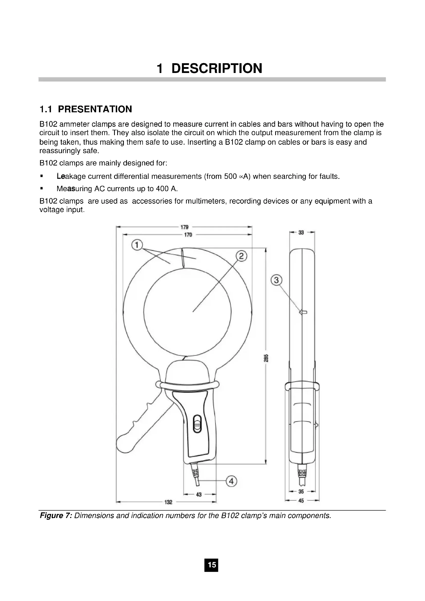
B102 ammeter clamps are designed to measure current in cables and bars without having to open the circuit to insert them. They also isolate the circuit on which the output measurement from the clamp is being taken, thus making them safe to use. Inserting a B102 clamp on cables or bars is easy and reassuringly safe. B102 clamps are mainly designed for:
Leakage current differential measurements (from 500 µA) when searching for faults.
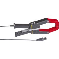
Measuring AC currents up to 400 A. B102 clamps are used as accessories for multimeters, recording devices or any equipment with a voltage input. Figure 7: Dimensions and indication numbers for the B102 clamp’s main components.16 The main components are as follows (Figure 1):
Jaws: gap: 112mm (1). Capacity with jaws open: 250 mm.
Clamping capacity: cable with a maximum diameter of 115 mm (2).
Current direction: arrow (3), visible on the side of the clamp, indicating the current’s direction. The current is deemed to be circulating in the positive direction when it flows from the current’s generator to the current’s consumer.
Output: voltage output, via a 1.5m-long cable moulded into the clamp and terminating in two 90° elbow male safety plugs.17 2 USE
Failure to observe the procedure described below risks causing a dangerously high voltage for the operator on the clamp’s output and causing damage to the clamp.
Do not clamp onto a conductor before connecting the clamp to the relevant measuring instrument. Also, do not disconnect the measuring instrument while the clamp is still gripping the cable.
Ensure that you keep the gap perfectly clean
Do not "click" the jaws together so as to avoid damaging the jaw faces.
1. Connect the cable from B102 clamp’s outlet to the multimeter paying careful attention to
2. Select the more appropriate rating on the clamp (P1, P2) and the appropriate size of
receiver for the output signal, which must be adequately insulated. Position on image Selector switch position Readout P1 400 A or 1 mV/A 400 mV for 400 A or 1 mV per A. P2 4 A or 1000 mV/A 1 mV for 1 mA or 1000 mV per A.
Figure 8: Reminder of the selector switch’s positions.
3. Open the jaws and clamp either the conductor whose current is to be measured or the
various conductors for the differential current measurements. Ensure that the clamp is correctly closed (no foreign body in the gap). Carefully observe the direction of the arrow, if the application requires this (source at the base of the arrow, receiver at the tip) mainly for mains system or power analysers.
4. Determine the current in the conductor by applying the appropriate readout coefficient to
the measured value according to the rating selected on the multimeter and the clamp’s sensitivity.18
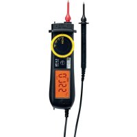
Figure 9: Principle for using the B102 ammeter clamp. Example: Measurement of an intensity of 22,77 A with a B102 clamp and a CA5220 multimeter.
The clamp’s selector switch is set to (P2) "4 x 1000".
The multimeter’s commutator is set to "V".
To measure the currents deriving from faults, simply clamp the active conductors to take the measurement. Please note:
The fault loop generally consists of an earth on one section of its circuit, which does not exclude the possibility of voluntary or faulty electrical connections between the main earth terminals for the installation and the supply.
One supply point, generally the Neutral supply, is connected directly to Earth and the masses are connected to Earth terminals, which are generally separate from those for the supply. Figure 10: Configuration in TT system.
The fault loop consists only of galvanic components. One supply point, generally the Neutral supply, is connected directly to Earth and the installation’s masses are connected to this point by protective conductors. A distinction must be made between three separate cases. "TNC" SYSTEM To measure the currents deriving from faults, place the clamp over the PEN Earth connections. Power supply earth 1, 2, 3 : measurement points19
Figure 11: Configuration in TNC system. "TNS" SYSTEM To measure the currents deriving from faults, separate the PE wire from the active wires. Figure 12: Configuration in TNS system.
To measure the fault currents, clamp the active conductors (Neutral included when distributed). Please note that the intensity limit for the current resulting from the fault is obtained either by inserting an impedance between a supply point (generally the Neutral supply) and Earth. Figure 7: Configuration in IT system. Power supply earth 1, 2, 3 : measurement points Power supply earth 1, 2, 3 : measurement points Power supply earth 1, 2, 3, 4, 5 : measurement points20 3 MAINTENANCE Only the specified replacement parts should be used for maintenance purposes. The manufacturer will not be held responsible for any accident occurring following any repairs made other than by its After Sales Service or approved repairers.
The clamp must necessarily be away from any conductor and disconnected from the measuring instrument.
Keep the jaw gap perfectly clean.
Clean the gap with a soft cloth if required.
Clean the clamp’s casing, arms and output cable with a sponge dampened with soapy water.
Rinse these parts with a sponge dampened with clean water.
Never run water over the clamp. Dry with a cloth or pulsed air (at a maximum temperature of 80°C).
3.2 METROLOGICAL VERIFICATION
Like all measuring or testing devices, the instrument must be checked regularly. This instrument should be checked at least once a year. For checks and calibrations, contact one of our accredited metrology laboratories (information and contact details available on request), at our Chauvin Arnoux subsidiary or the branch in your country. Repairs For all repairs before or after expiry of warranty, please return the device to your distributor.21 4 CHARACTERISTICS
4.1 REFERENCE CONDITIONS
Ambient temperature: 23°C ± 3K. Relative humidity: 20 to 75% RH. Position of the conductor: Centred in the jaws. Current frequency and form: Sinusoidal 50 and 60 Hz ± 0.2 Hz, distortion < 1%. Superimposed DC current: No DC current. Continuous magnetic field: Earth field < 40 A/m Alternating magnetic field: No external alternating magnetic field. Proximity of external conductors: None. Measuring device’s impedance: ≥ 10 MΩ / 100 pF.
4.2 PRECISION AND DEPHASING
Under the reference conditions
The B102 clamp must be used under the conditions defined above in order to meet the requirements for operator safety and the metrological performance levels.
Peak current: < 1000A.
Conductor temperature: ≤ 70°C with a maximum peak of 90°C.
For use from 48 Hz to 1 kHz.
4.3.3 ENVIRONMENTAL CONDITIONS
The graph shows the air temperature and humidity conditions for the casing. : Reference range. : Operating range. : Storage range.
Pollution level 2 to IEC 61010 .
Operating altitude: ≤2000m on uninsulated conductors.
Transport altitude: ≤12000m.23
Position of the gripped conductor : (max with not centred conductor) 0.1% typic of Vs (non-differential current) ; 0,2% max.
Residual differential : (max with not centred conductor) 0.1% typic of IP (differential current) ; 0,2% max .
Coupled DC current, 1V/A (2): < 1 mV for continuous 1A.
Coupled DC current, 1mVm/A (2): < 0.1 mV for continuous 1A.
Frequency, 1 V/A (3): < 1.5% from 30 Hz to 1 KHz.
Frequency, 1 mV/mA (3): < 0.5% from 30 Hz to 1 KHz. (1): 400 A/:m 50 Hz field perpendicular to the clamp opening. (2): DC current coupled onto an AC current. (3): Limited to 1 KHz for 100A.
4.3.5 DIMENSIONS AND WEIGHT
Weight: 1300 g approx.
Clamp opening: 112 mm.
Double-insulated appliance.
Industrial environment: criterion B.
Susceptibility (to EN 61326-1). Self-extinguishing capability
Jaws and casing: VO (to UL 94).24