Y2N - Measuring equipment CHAUVIN ARNOUX - Free user manual and instructions
Find the device manual for free Y2N CHAUVIN ARNOUX in PDF.
Download the instructions for your Measuring equipment in PDF format for free! Find your manual Y2N - CHAUVIN ARNOUX and take your electronic device back in hand. On this page are published all the documents necessary for the use of your device. Y2N by CHAUVIN ARNOUX.
USER MANUAL Y2N CHAUVIN ARNOUX
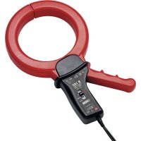
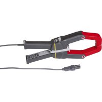
The Y2N 1000:1 current clamp is designed for alternating current measurements in low-voltampere systems, from 4 A to 500 A AC (up to 600 A AC max - see § 4.3.1). The asymmetrically shaped jaws clamp around cables or busbars. The Y2N connects to any multimeter, recorder, etc. having an alternating-current input with an impedance of ≤10 Ω or less. It features dual or reinforced insulation and conforms to international standards, such as IEC 1010-2-032 "Current clamps" (see § 4.4).
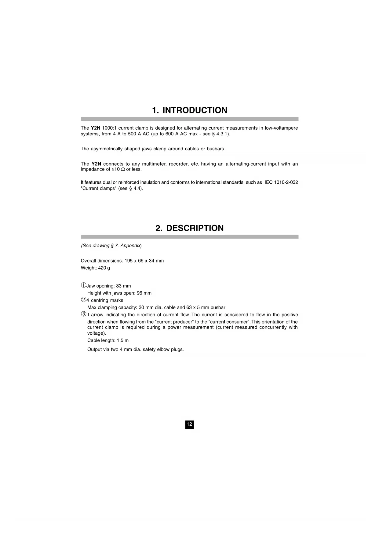
(See drawing § 7. Appendix
Overall dimensions: 195 x 66 x 34 mm Weight: 420 g ➀ Jaw opening: 33 mm Height with jaws open: 96 mm ➁ 4 centring marks Max clamping capacity: 30 mm dia. cable and 63 x 5 mm busbar ➂ I arrow indicating the direction of current flow. The current is considered to flow in the positive direction when flowing from the "current producer" to the "current consumer". This orientation of the current clamp is required during a power measurement (current measured concurrently with voltage). Cable length: 1,5 m Output via two 4 mm dia. safety elbow plugs.13
Although there is no special hazard, do not clamp a conductor before connecting the current clamp to the multimeter. Similarly, do not disconnect the current clamp from the multimeter when the clamp is closed around a cable (see § 4.3.3. Environmental conditions). Before connecting the current clamp to the multimeter, check that the multimeter has an impedance range compatible with the maximum allowable current clamp load (nominal load 5 Ω). Open the jaws and clamp the cable carrying the current to be measured. Centre the cable using the marks. Observe the direction of the I arrow if required by the application. To read the measured current, apply the appropriate reading cœfficient for the range selected on the multimeter. The current clamp delivers 1 mA AC for a current of 1 A AC. From 500 A to 600 A, limit the current clamp operating time: 10 minutes on and 30 minutes off. AC mains power Load black red COM A14
■ Temperature : 18 to 28°C ■ Relative humidity : 20 to 75% ■ Conductor centred in the jaws ■ Sinusoidal current : 48 to 65 Hz ■ No direct current ■ Instrument impedance : 2.5 Ω ≤ Z ≤ 5 Ω (at 1.25 VA) ■ Direct-current magnetic field : earth’s magnetic field (< 40 A/m) ■ External conductor proximity : no direct of alternating current ■ Intrinsic error or phase difference NOTE : Linear interpolation between each value (see also the graphs in § 7. APPENDIX) Current to be in A AC 4 A 25 A 100 A 250 A 500 A 600 A (2) measured in % of In 0.8% 5% 20% 50% In 120% Intrinsic error (1) 3% +0.5 A 3% 1.5° 1% Phase difference (3) 3° 1.5° 1° (1) In ±% of the output (2) See § 4.3.1 Overloads (3) Unspecified
■ Accuracy class : class 1 (at 1.25 VA) in accordance with IEC 18515
4.3 Operating conditions and influences
The current clamp must be used under the following conditions to meet the user safety and measuring performance requirements.
Limit the operating time above 500 A Current I ≤ 500 A AC 500 A AC < I ≤ 600 A AC Working continuous operation 10 minutes on 30 minutes off
4.3.2 Influence on frequency
Values to be added to the reference conditions. NOTE : linear interpolation between each specified value (see also the graphs in § 7 APPENDIX). Frequency 65 Hz to 1000 Hz Current to be in A AC 4 A 25 A 100 A 250 A 500 A 600 A measured in % of In 0.8% 5% 20% 50% In 120% Error to be added 2% +1 A 4° Phase difference to be added (1) 6° 5° 4° (1) Unspecified
4.3.3 Environmental conditions
■ Climatic conditions:16
4.4 Conformity to international standards
4.4.1 Electrical safety (in accordance with IEC 1010-2-032)
- Degree of protection IP20 (i.a.w. IEC 529) with jaws closed - Free fall: 1.5 m (i.a.w. IEC 68-2-32) - Shock: 100 g (i.a.w. IEC 68-2-27) - Vibration: 0.15 mm - 10/55/10 Hz (i.a.w. IEC 68-2-6)
4.4.4 Flammability rating
The instrument contains no parts that can be replaced by personnel who have not been specially trained and accredited. Any unauthorized repair or replacement of a part by an "equivalent" may gravely impair safety.
The clamp must be disconnected from all electrical sources and not enclose a cable. Do not subject the clamp to running water.
■ Keep the jaw faces perfectly clean. The jaw faces must be cleaned with a lightly oiled soft cloth.
■ Clean the case with a cloth slightly moistened with soapy water. Rinse with a dry cloth. Then dry quickly with a cloth or in a hot air stream ( 80 °C max.)
5.2 Metrological verification
Like all measuring or testing devices, the instrument must be checked regularly. This instrument should be checked at least once a year. For checks and calibrations, contact one of our accredited metrology laboratories (information and contact details available on request), at our Chauvin Arnoux subsidiary or the branch in your country.
For all repairs before or after expiry of warranty, please return the device to your distributor.