J93 - Measuring equipment CHAUVIN ARNOUX - Free user manual and instructions
Find the device manual for free J93 CHAUVIN ARNOUX in PDF.
Download the instructions for your Measuring equipment in PDF format for free! Find your manual J93 - CHAUVIN ARNOUX and take your electronic device back in hand. On this page are published all the documents necessary for the use of your device. J93 by CHAUVIN ARNOUX.
USER MANUAL J93 CHAUVIN ARNOUX
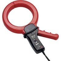
J93 and J193 Hall effect ammeter clamps are used to measure DC currents up to 5000A and AC currents up to 3500A, without opening the circuit 1.1. J93 CLAMP The J93 clamp is powered by a battery. 5000A 500A ZERO StopTest MARCHE SORTIE ZERO
Jaws. Guard. Specific 4‑point plug. Shielded cord. Zero adjustment. Indicator that indicates that the clamp is on or that the battery is low. Three‑position switch (ON, OFF, battery test). Battery com‑ partment cover. Arm.19 1.2. J193 CLAMP The J193 clamp is powered by the device to which it is connected. ZERO
Jaws. Guard. Specific 4‑point plug. Shielded cord. Zero adjustment. Arm.20
Set the switch to n order to check that the battery is OK. If the indicator lights, the battery must be replaced (see §4.2). 5000A 500AZERO StopTest MARCHE SORTIE ZERO
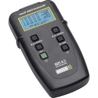
Set the switch to ON. The indicator lights.
2.2. FOR THE J93 AND J193 CLAMPS
Connect the clamp to the device, on one of the current inputs. Switch on the device. Adjust the zero by watching the display of the device and turning the zero adjustment knob until the device displays 0. 5000A 500A ZE RO Stop Test MARCHE SORTIE ZERO
QUALI STAR +21 Open the jaws of the clamp by moving the arm closer. Clamp the conductor carrying the current to be measured. There must be only one conductor in the jaws of the clamp. Gently close the jaws. In order to optimize measurement quality, centre the conductor as accurately as possible in the jaws. Read the measurement on the device. When the measurement is over, open the clamp and withdraw the conductor. Then disconnect the clamp from the device. Switch off the device.
3.1. REFERENCE CONDITIONS Quantity of influence Reference values Temperature 23±5°C Relative humidity 20 to 75% RH DC signal With an AC signal of which the distortion factor is <0.1% AC signal 45 to 65 Hz with a DC signal <0.1% Supply voltage J93: 9 V ± 0.1 V J193: 5 V ± 0.1 V External electric field Zero External DC magnetic field (earth’s field) < 40 A/m External AC magnetic field Zero Position of the conductor centred in the measurement ring 3.2. ELECTRICAL CHARACTERISTICS Measurement range 50 A - 3 500 Aac 50 A - 5 000 Adc Sensitivity 1 V / 3 500 A Output impedance ≥ 100 kW Frequency DC to 3 kHz (‑3 dB typical) Primary current (AC/DC) [50 - 100[ [100 - 500[ [500 - 2 000[ [2 000 - 3 500] ]3 500 - 5 000] DC only Amplitude error (see the curve in §3.4.1) ± 2% ± 2.5 A ± 1.5% ± 2.5 A ± 1% ± 1% ± 1% Phase error (see the curve in §3.4.2) 4° 2° 1° 1.5° ‑ Zero adjustment: ± 200 A in 25 turns23
3.3. VARIATIONS IN THE RANGE OF USE
Quantity of influence Range of influence Uncertainty Temperature ‑10 to + 55 °C < 0,7 % / 10 °C Relative humidity 10 to 90% HR < 0,7 % Frequency response DC at 2 kHz See the curve in § 3.4.4 Phase shift DC at 2 kHz See the curve in § 3.4.5 Position of the conductor in the sensor Any position
< ± 2 % Conductor adjacent Conductor touching the jaws
Rejection > 35 dB Battery voltage J93: from 6,5 to 10 V J193: 4,75 to 5,25 V ± 2,25 A typique Remanence at 5 000 Adc < 2 A Earth's magnetic field < 0,5 A 1: Test performed with a 40x30 mm² cable and a current of 3500 A at 50 Hz. The error in % is the ratio of the maximum variation to the mean value. 2: Test performed with a current of 300 A at 50 Hz. 3.4. TYPICAL CURVES
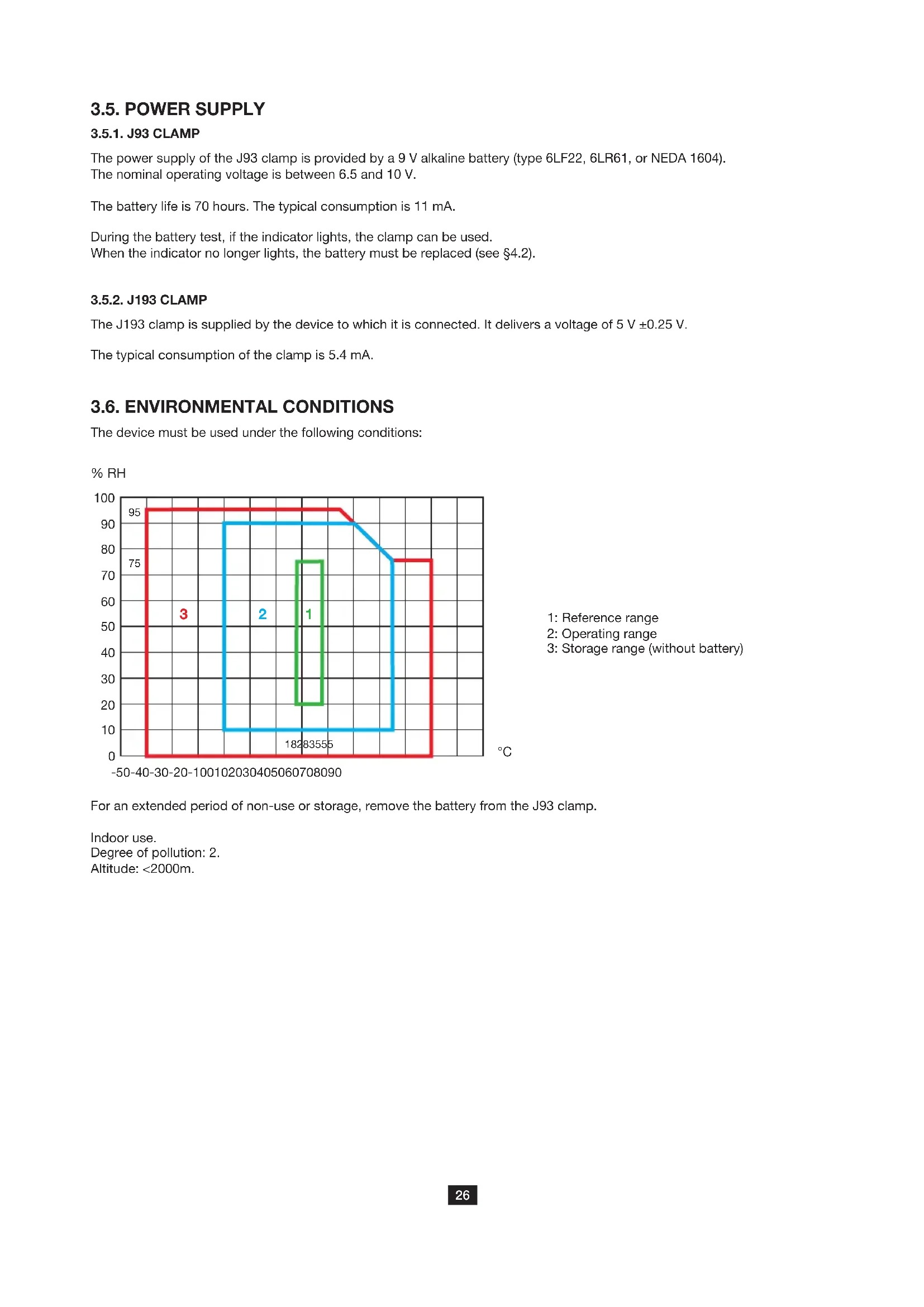
The power supply of the J93 clamp is provided by a 9 V alkaline battery (type 6LF22, 6LR61, or NEDA 1604). The nominal operating voltage is between 6.5 and 10 V. The battery life is 70 hours. The typical consumption is 11 mA. During the battery test, if the indicator lights, the clamp can be used. When the indicator no longer lights, the battery must be replaced (see §4.2).
The J193 clamp is supplied by the device to which it is connected. It delivers a voltage of 5 V ±0.25 V. The typical consumption of the clamp is 5.4 mA. 3.6. ENVIRONMENTAL CONDITIONS The device must be used under the following conditions: % RH
1: Reference range 2: Operating range 3: Storage range (without battery) For an extended period of non‑use or storage, remove the battery from the J93 clamp. Indoor use. Degree of pollution: 2. Altitude: <2000m.27 3.7. CONSTRUCTION SPECIFICATIONS Dimensions (L x W x H) 336 x 127 x 42 mm Clamping diameter 72 mm
Cord 3 metres long Weight approx. 1.7kg Protection index: IP20 according to IEC 60529
3.8. CONFORMITY TO INTERNATIONAL STANDARDS
Electrical safety according to IEC 61010‑2‑032 for type A sensors. Maximum applicable voltage: 600V Cat. IV or 1000V Cat. III. 3.9. ELECTROMAGNETIC COMPATIBILITY (EMC) Emissions and immunity in an industrial environment in accordance with IEC 61326‑1, except for immunity to the electric field with a criterion B.28
Except for the battery, the instrument contains no parts that can be replaced by personnel who have not been spe- cially trained and accredited. Any unauthorized repair or replacement of a part by an “equivalent” may gravely impair safety. 4.1. CLEANING Disconnect the current clamp completely and switch it OFF. Use a soft cloth, dampened with soapy water. Rinse with a damp cloth and dry rapidly with a dry cloth or forced air. Do not use alcohol, solvents, or hydrocarbons. Keep the clamp jaws as clean as possible. 4.2. REPLACING OF THE BATTERY (J93 CLAMP) Disconnect anything connected to the J93 clamp and switch it off. Spent batteries must not be treated as ordinary household waste. Take them to the appropriate recycling collection point. Then place the shim. Put the battery compartment cover back in the slide and push it in until you hear a click. 4.3. METROLOGICAL CHECK Like all measuring or testing devices, the instrument must be checked regularly. This instrument should be checked at least once a year. For checking and calibration, contact one of our accredited metrology laboratories (information and contact details available on request), at our Chauvin Arnoux subsidiary or the branch in your country. 4.4. REPAIR For all repairs before or after expiry of warranty, please return the device to your distributor. Insert a tool, not more than 3 mm in diam‑ eter, in the hole in the battery compartment cover. Push to unlock the bat‑ tery compartment cover, then slide it off. Remove it completely by hand. Remove the battery and the shim from the compartment. Place the new battery in the compartment with the polar‑ ity as indicated on the label. BEFORE OPENING CASE TO AVOID ELECTRIC SHOCKSREMOVE THE CLAMP FROM ALL CONDUCTORSAND REMOVE THE OUTPUT WARNING 9 V
Except as otherwise stated, our warranty is valid for twelve months starting from the date on which the equipment was sold. Extract from our General Conditions of Sale provided on request. The warranty does not apply in the following cases: Inappropriate use of the equipment or use with incompatible equipment; Modifications made to the equipment without the explicit permission of the manufacturer’s technical staff; Work done on the device by a person not approved by the manufacturer; Adaptation to a particular application not anticipated in the definition of the equipment or not indicated in the user’s manual; Damage caused by shocks, falls, or floods.