
1703REV - Garage door CHAMBERLAIN - Free user manual and instructions
Find the device manual for free 1703REV CHAMBERLAIN in PDF.
| Product Type | Door Arm for Garage Door Opener |
| Brand | Chamberlain |
| Model | 1703REV |
| Compatibility | One-piece tilt-up doors and double-sliding doors (vertical and horizontal). Not suitable for sectional doors, completely retractable doors, or tilt-up doors with legs. |
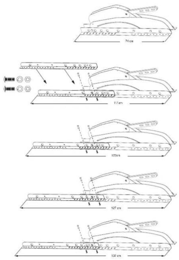
| Door Width (without additional profile) | Approximately 74 cm |
| Door Width (with additional profiles) | 117, 122, 127 or 132 cm |
| Material | Steel |
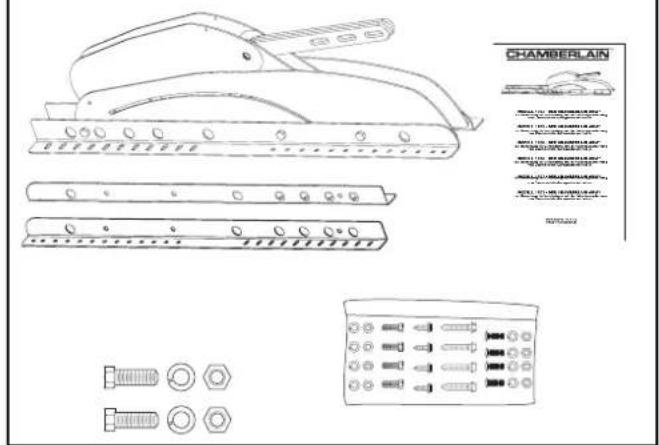
| Included Components | Door arm, carriage, header bracket, extension arm, release handle, fasteners (bolts, screws, nuts, washers) |
| Main Functions | Enables motorized opening and closing of tilt-up garage doors; designed for use with a Chamberlain garage door opener. |
| Safety | Requires installation of the The Protector System (photo-electric sensors). Remove all manual locking mechanisms. |
| Installation | Fix the header bracket above the door, assemble the arm and carriage, adjust the travel limits, and perform force learning. Requires drilling and leveling tools. |
| Maintenance | Periodically lubricate all moving parts (rollers, hinges). Check door balance: it should stay at mid-travel when released. |
| Troubleshooting | If the motor does not open fully, reduce travel or reprogram force. If door sticks, check balance and lubricate. See manual for specific issues. |
| Spare Parts and Repairability | Additional profiles available to extend range. Screws and bolts supplied. For complex repairs, contact a professional installer. |
| Weight | Approximately 1.5 kg (estimated) |
Frequently Asked Questions - 1703REV CHAMBERLAIN
User questions about 1703REV CHAMBERLAIN
0 question about this device. Answer the ones you know or ask your own.
Ask a new question about this device
Download the instructions for your Garage door in PDF format for free! Find your manual 1703REV - CHAMBERLAIN and take your electronic device back in hand. On this page are published all the documents necessary for the use of your device. 1703REV by CHAMBERLAIN.
USER MANUAL 1703REV CHAMBERLAIN
natural_image
Line drawing of a mechanical device with multiple slots and a handle (no text or symbols)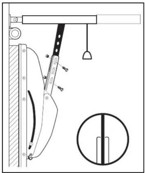
natural_image
Technical line drawing of a mechanical device with attached components and a circular inset showing a vertical bar (no text or symbols)de
MODEL 1703EV/REV - THE CHAMBERLAIN ARM™ To be used in conjunction with the Chamberlain Garage Door Operator Owner's Manual
it
natural_image
Pure mechanical diagram showing a lever and rod assembly without any text, numbers, or symbolsnatural_image
Technical line drawing of a structural support frame with diagonal bracing (no text or symbols)natural_image
Illustration of a person standing beside a large window or panel, viewed from behind (no text or symbols present)Zusammenbau
natural_image
Technical diagram of a mechanical device with a tool and hanging weights (no text or symbols)ABB. 15

natural_image
Simple line drawing of a pendulum hanging from a horizontal beam, with a cross symbol between two metal bars (no text or symbols)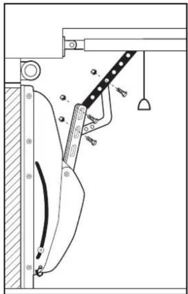
natural_image
Technical line drawing of a mechanical assembly with no visible text or symbols

WARNUNG
natural_image
Technical line drawing of a vertical pipe or support structure with no visible text or symbolsnatural_image
Technical line drawing of a structural support frame with diagonal bracing and vertical supports (no text or symbols)natural_image
Illustration of a person standing beside a large wall, possibly a window or bench, with no visible text or symbols.natural_image
Technical line drawing of a mechanical component with 74 cm scale indicator (no text or symbols)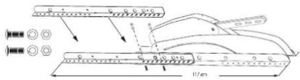


Planification
natural_image
Technical diagram of a mechanical device with a tool and hanging weights (no text or symbols)FIG. 15

natural_image
Simple line drawing of a pendulum hanging from a horizontal beam, with a cross-shaped object and a ruler-like object below (no text or symbols)
natural_image
Technical line drawing of a mechanical assembly with a lever and hanging weights (no text or symbols)
AVERTISSEMENT
natural_image
Technical line drawing of a mechanical support structure with diagonal braces and vertical supports (no text or symbols)natural_image
Technical line drawing of a structural support frame with diagonal bracing (no text or symbols)natural_image
Illustration of a person standing beside a large window or panel, no text or symbols visiblenatural_image
Technical diagram of a mechanical device with a tool and hanging weights (no text or symbols)AFB. 15

natural_image
Simple line drawing of a pendulum hanging from a horizontal beam, with a cross-shaped object and a ruler-like object below (no text or symbols)
natural_image
Technical line drawing of a mechanical assembly with a lever and hanging weights (no text or symbols)

WAARSCHUWING
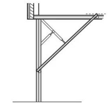
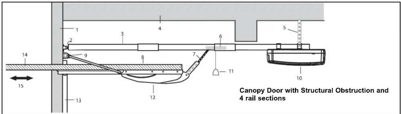
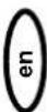
For use only with one-piece canopy and dual track doors as illustrated. Do not use this door arm with sectional doors, fully retractable doors or canopy doors with jamb hardware.
natural_image
Pure mechanical diagram showing a lever and rod assembly without any text, numbers, or symbolsOne-Piece Canopy Door (vertically tracked)
natural_image
Technical line drawing of a structural support frame with diagonal bracing (no text or symbols)One-Piece Door with Dual Track (vertical and horizontal)
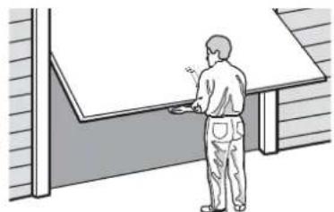
Review all safety warnings on Page one of your garage door operator owner's manual. Ensure that the door and all its operating gear is in good condition and works easily when it is manually operated.
Balance Test
Lift the door about halfway. Release the door. It should stay in place, supported entirely by its springs.
Raise and lower the door to see if there is any binding or sticking. If your garage door binds, sticks or is out of balance, call a professional garage door service engineer.
natural_image
Illustration of a person standing near a window or bench (no text or symbols visible)Lubricate all garage door working parts before installing the door arm. Ensure that the timber or metal garage door frame on both sides and above the door is in good and sound condition and is securely fixed to the main structure of the garage. If there is any doubt, consult a professional garage door installer. (See the Yellow Pages under Garage Doors)
Do not run the operator until installation is complete.
Content
Assembly
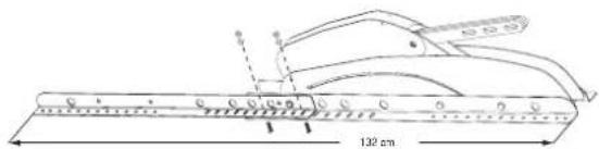
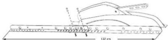
Possible overall length using additional profiles: 117 cm or 122 cm or 127 cm or 132 cm. Length without profiles: ca. 74 cm
Planning
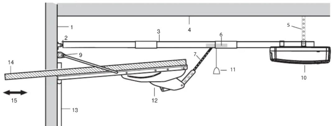
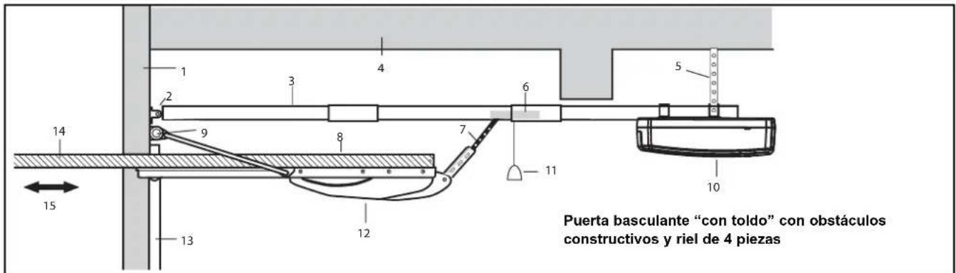
You may find it helpful to refer to the applicable illustration as you proceed with the installation of your garage door operator and The Chamberlain Arm™. The garage door opener must be installed parallel to the floor.
Follow rail assembly instructions as shown in the Owner's manual. For fitting rail with canopy arm use this manual.
- Header wall
- Header bracket
- Garage door opener rail
- Ceiling
- Garage door opener hanging brackets
- Trolley
- Extension arm
- Garage door
- Garage door spring
- Operator
- Garage door opener manual release
- Chamberlain Arm™
- Garage door track
- Garage door, should be horizontal in fully open position
- Use limit adjustment of garage door opener to level the garage door
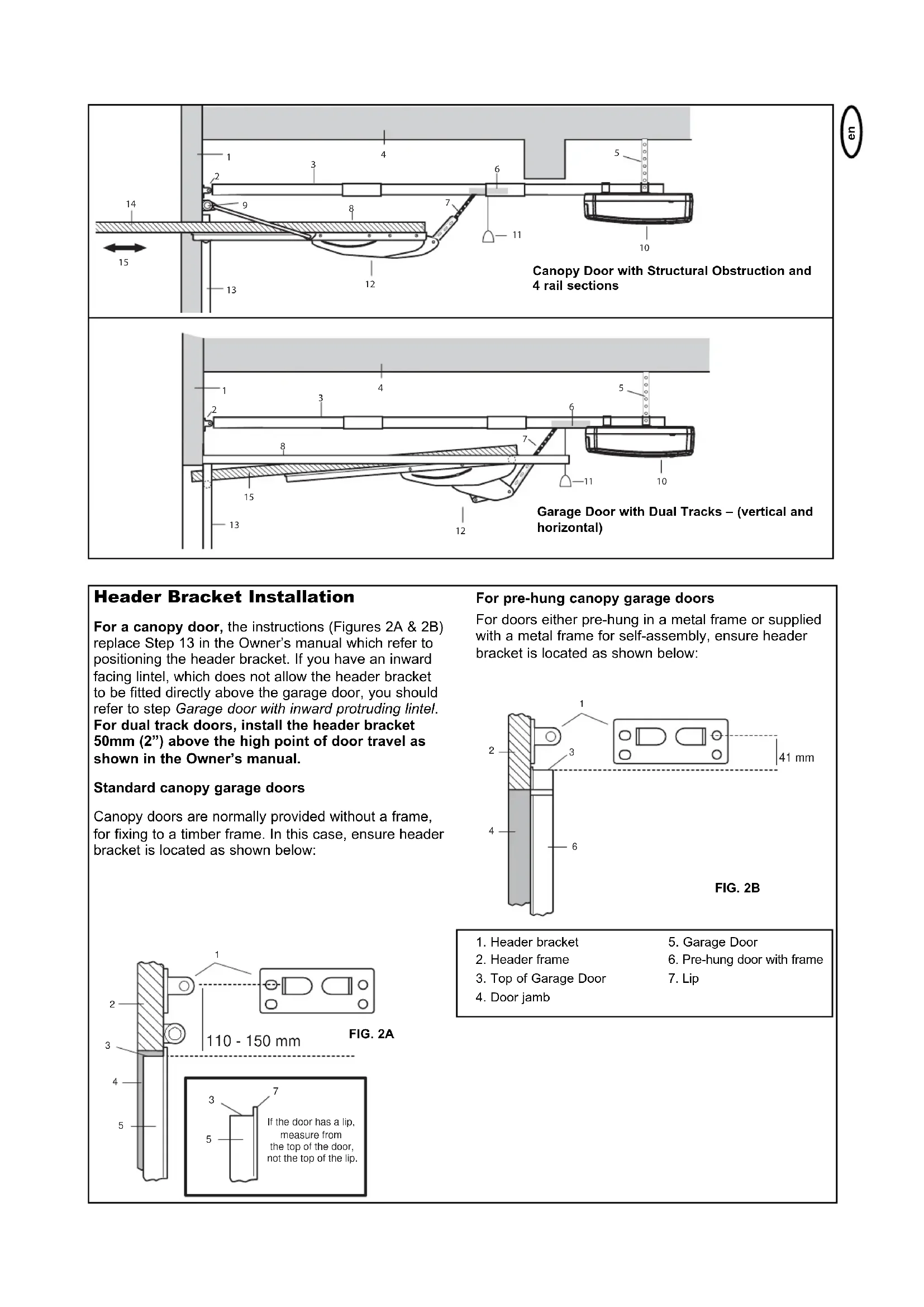
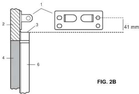
Header Bracket Installation
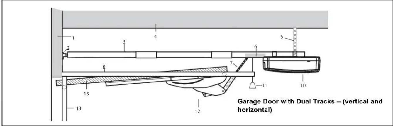
For a canopy door, the instructions (Figures 2A & 2B) replace Step 13 in the Owner's manual which refer to positioning the header bracket. If you have an inward facing lintel, which does not allow the header bracket to be fitted directly above the garage door, you should refer to step Garage door with inward protruding lintel. For dual track doors, install the header bracket 50mm (2") above the high point of door travel as shown in the Owner's manual.
Standard canopy garage doors
Canopy doors are normally provided without a frame, for fixing to a timber frame. In this case, ensure header bracket is located as shown below:
For pre-hung canopy garage doors
For doors either pre-hung in a metal frame or supplied with a metal frame for self-assembly, ensure header bracket is located as shown below:
- Header bracket
- Garage Door
- Header frame
- Pre-hung door with frame
- Top of Garage Door
- Lip
- Door jamb
WARNING
en
To prevent damage to garage door and operator: Ensure that turning the outside handle will not actuate ANY of the locking mechanisms supplied with the door.
Representative Locking Mechanism
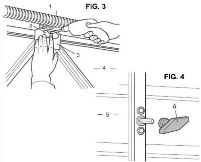
- Spring
- Inside of Canopy Door
- Latch
- Door Plate
- Remove inside Door Handle
-
Canopy Door
-
Remove all door latching mechanisms (Figure 3), and secure any locking bars in the open position.
- Remove inside door handle but leave the barrel in place in door (Figure 4).
- Ensure that turning the outside handle will not actuate ANY of locking mechanism supplied with the door. Failure to do so will result in serious damage to your door and operator. This is not covered by the Manufacturer's Warranty.
Door Conditions
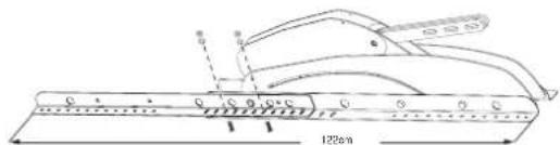
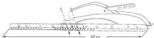
Check if additional profiles are needed. Adjust length if necessary. Possible overall length with additional profiles: 117cm or 122cm or 127cm or 132 cm. Doorarm and profiles must be tightened properly to the framework.
- Canopy Door
- Door Arm
- Cross Bracing
- Profiles
Note:
The door arm should extend about 13mm (1/2") over the top of the door. If not, check hole positions.
The garage door may require additional bracing to provide suitable support.
To prevent damage to garage door, do NOT drill through the entire door.
Door Arm Installation
- With a 4.5mm (3/16") bit, drill two holes, 25mm (1") deep.
FIG. 12
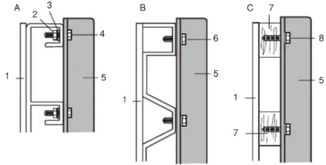
- Attach the door arm with proper hardware provided (Figure 12).
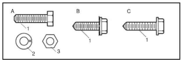
Note: Whenever possible, use the nuts and bolts supplied (A).
For metal or metal-braced doors, use self-tapping screws supplied (B). For timber or timber-braced doors, use wood screws supplied (C).
- Before tightening the screws, align the door arm so it is vertical. Use a level to assist. The tighten the screws.
| 1. Exterior of Door | 5. Door Arm |
| 2. Nut | 6. Self-trapping screw |
| 3. Lock Washer | 7. Timber support |
| 4. Bolt | 8. Lag screw |
A
- Bolt
- Lock Washer
- Nut
B
- Metal or Metal-Braced
C
- Timber or Timber-Braced
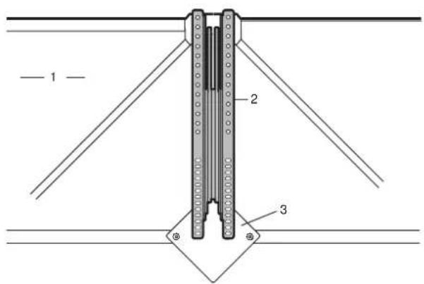
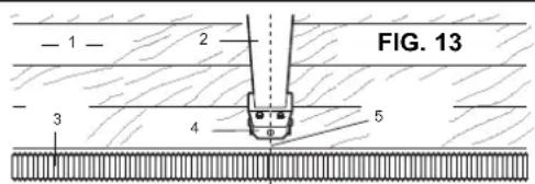
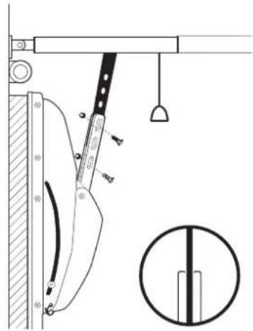
Connecting the Extension Arm
- Select the two bottom holes in the door arm that will allow the screws to go into a cross bracing support of the door (Figure 13). Door may REQUIRE ADDITIONAL bracing to provide suitable support.
- Mark and drill two 4.5mm (3/16") holes. Use the proper screws provided.
The centerline of the garage door opener and the centerline of the door arm should match to prevent binding of the arm in operation.
- Recheck and if not aligned, correct.
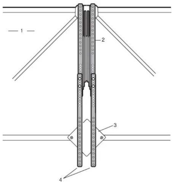
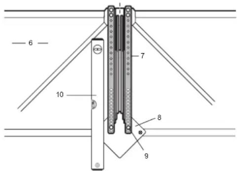
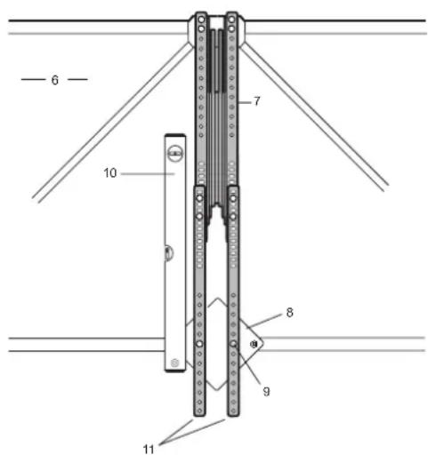
- With the door fully closed, slide outer trolley (with extension arm connected), against door arm. Line up the extension arm and insert into slot in door arm (Figure 14).
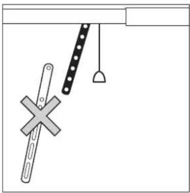
Note: Do not move the door arm to meet the extension arm—move the extension arm to meet the angle of the door arm.
- Insert the two mounting bolts provided into holes as far apart as possible and tighten (Figure 15).
-
Cut off the shipping cable tie to release the mechanism (Figure 14 and Figure 15).
-
Header Wall
- Rail Assembly
- Door Spring
- Header Bracket
- Centerline of Header Bracket
-
Canopy Door
-
Door Arm
- Cross Bracing
- Mounting Screw
- Door Arm must be vertical (use level)
- Profiles
Standard Assembly (Door mounted inwards)
FIG. 14
natural_image
Technical diagram of a mechanical device with a tool and hanging weights (no text or symbols)FIG. 15

Garage door with inward protruding lintel
-
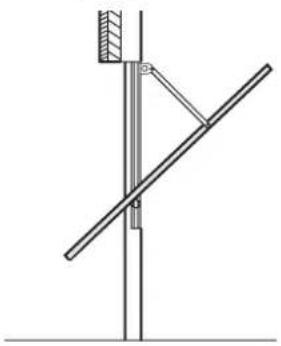
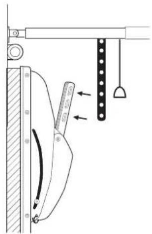
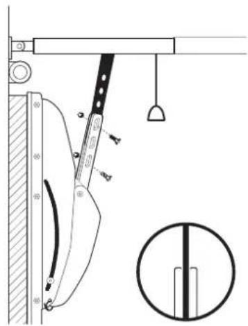
To install the Chamberlain Door Arm at inward protruding lintel situations the door arm must be mounted in a different way.
-
Cut down the door arm supplied with your garage door opener (275mm).
- Mount the cut down door arm to the trolley as shown. Do not use the slotted arm supplied with the Chamberlain Door Arm.
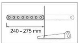
- Take the curved door arm supplied with the Garage Door Opener and fit all as shown together. If you disconnect the trolley you can move it easily in any position for the installation. Use M8 screws with lock nuts (not supplied).
natural_image
Simple line drawing of a pendulum hanging from a horizontal beam, with a cross-shaped object and a ruler-like object below (no text or symbols)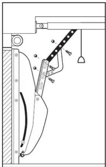
natural_image
Technical line drawing of a mechanical device with lever and clamped parts (no text or symbols)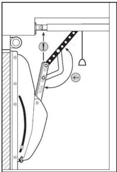
- Tighten the screws fully and back them off again 1/2 turn.
Open the garage door slowly and carefully by hand. Watch the movement of the door arm. If the Chamberlain Door Arm hits the rail before the garage door is fully open, the angle of the arms must change. Close the garage door and use another hole to change the angle of the system. Try again until the Chamberlain Door Arm does not hit the rail anymore. In some cases raising the operator head is quicker.
Initial Operation:
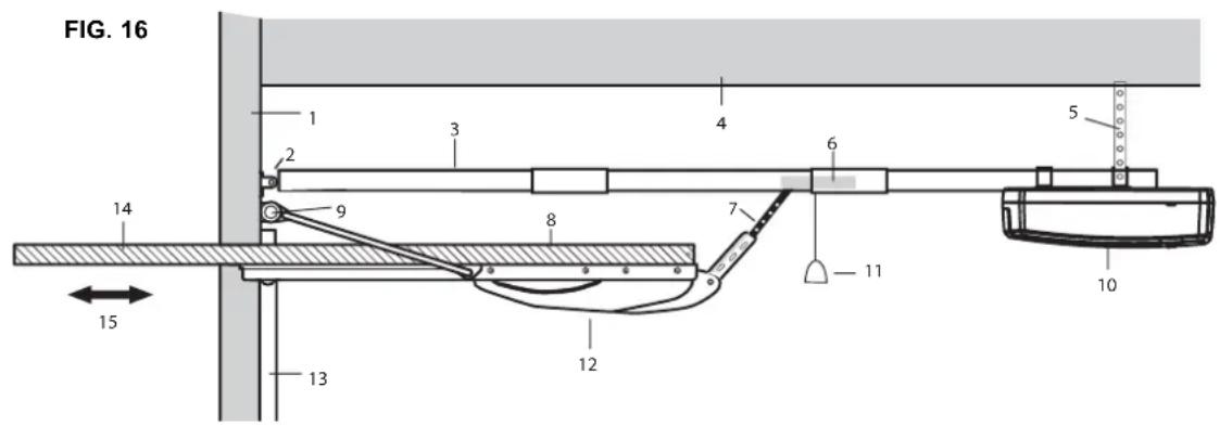
The Chamberlain Arm ^™ has been designed so that, when used with a Chamberlain manufactured operator, the door will open to a fully horizontal position (Figure 16).
Note: The door may be designed in such a way that it does not open to the full horizontal. Adjust the UP limit so that the door stops at a slightly downward angle when open.
Note: Safety reversing sensors (Protector System) must be installed, please refer to your owner's manual before proceeding to Setting the limits and learning the force:
Setting the limits and learning the force:
When returning to your Owner's Manual, adjust the trolley travel limits as follows:
- With the inner and outer trolley sections still disconnected, manually open your door to the horizontal position. Make a mark on the rail where the end of trolley nearest to the operator stops.
- Manually close the door and mark the rail where the end of the trolley nearest the door stops.
- With the inner and outer trolley sections still disconnected, activate the operator and adjust the limits following the owners manual of the garage door opener, until the inner trolley stops on the marks you made.
- Reconnect the inner and outer trolley sections so the door is connected to the operator.
- Force must be learned after completion of the limit settings. Please read accordant section in Garagedoor Opener Manual.
- Run the operator again to ensure the door is opening and closing correctly.
Continue with the instructions in your Owner's Manual.

WARNING
Do not attempt to adjust the spring. Call a local garage door installing professional.
The Protector System ^™ (a safety reversing sensor accessory) must be installed, if the Chamberlain Arm is used.
- Header wall
- Header bracket
- Garage door opener rail
- Ceiling
- Garage door opener hanging brackets
- Trolley
- Extension arm
- Garage door
-
Garage door spring
-
Operator
- Garage door opener manual release
- Chamberlain Arm™
- Garage door track
- Garage door, should be horizontal in fully open position
- Use limit adjustment of garage door opener to level the garage door
| Having a problem?1. Pull the manual release handle to disengage the trolley.2. Lift the door about halfway. Release the door. It should stay in place, supported entirely by its springs.3. Raise and lower the door to see if there is any binding or sticking. If your garage door binds, sticks or is out of balance, call a professional garage door service engineer.ISSUE POSSIBLE REMEDIES | |
| Operator moves only in OPEN direction but not in CLOSE direction | ·The travel distance hasn't been programmed at all or hasn't been programmed properly. Only possible when installed for the first time.·Some models will only close the door, if photocells are connected. In this case photocells are included.·Release operator and check if it closes. If so, do the force adjustment |
| Operator doesn't fully open the door to the marked position. It stops and reverses. | ·The marked position is too close to the operator. Because of the operator this position can't be used. Some doors can't be opened to the full horizontal position. Readjust travel distance (shorter).·The force adjustment hasn't been programmed properly and the operator moves inefficiently.·Doorarm must be fully extended shortly before reaching its final position. If it's not, check the distance between rail and door.·Door is too heavy or insufficiently balanced in OPEN direction. Rebalance door (call a trained technician or have it repaired) Grease track rollers and hinges. |
| Operator doesn't fully open the door to the marked position. It stops but doesn't reverse. | ·Travel distance too short. Readjust!·Doorarm screws were not tightened.·Door is distorted. |
| The connection arm can't be installed between door and operator. | ·Is the operator properly installed (just above the door)?·Is the doorarm properly installed?·Doorarm must be fully retracted when the door is closed. |
| Door can be opened with the operator but cannot be closed from the open position. The operator moves a little (appr. 1 sec) and then reverses. | ·Operator reverses because the adjusted force is lower than the required force. Readjust force. Test: Standing in front of the door you can „help" the door to move from the open position by pulling at the door for the first 50cm. This confirms that the adjusted force was too low.·The door has passed over the horizontal position and is facing upwards. In this case readjust travel distance (shorter).·If the operator will close the door during the force learning but doesn't close the door later on, this is due to a bumpy not smooth running door.·Remedies:·A: Readjust travel distance. Do not open door too far.·B: The spring pulls the door upwards strongly and therefore the door is unbalanced. The operator now requires too much force in order to move the door down. Diminish (readjust) tension of door spring.·C: Rail vibrates due to high force. A spacer (e.g. a piece of wood) between ceiling and rail avoids vibrating and bending of the rail.·The remedies mentioned may occur combined.·If the door functions properly and is well balanced then also the operator will function properly. |
| The door touches the rail | In rare installations, the canopy door may touch the operator rail when closing. This is NOT the fault of the operator or arm. If this occurs:1. Manually check the operation of the canopy door to ensure that it is closing easily. The door must have a slight drop at the start of closing.2. If the door is not running easily, check that the side wires are not catching or binding on the wire guides. Move the guides until the wires run free.3. Raise the operator head by about 50mm (2") vertically so there is a slight downward angle on the rail.4. The door spring may be over tensioned. |
natural_image
Illustration of a person standing beside a window with a magnifying glass (no text or symbols)Assemblaggio
natural_image
Technical line drawing of a mechanical component with 74 cm scale indicator (no text or symbols)


Progetto
natural_image
Technical line drawing of a mechanical device with a tool and hanging weights (no text or symbols)FIG. 15
natural_image
Simple line drawing of a pendulum hanging from a horizontal beam, with a cross-shaped object and a ruler-like tool below (no text or symbols)
natural_image
Technical line drawing of a mechanical assembly with no visible text or symbols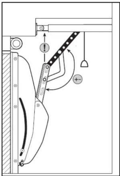
AVVERTIMENTO
natural_image
Pure technical diagram of a mechanical or structural assembly without any text, numbers, or symbolsnatural_image
Technical line drawing of a structural support frame with diagonal bracing (no text or symbols)natural_image
Illustration of a person standing beside a window with a magnifying glass (no text or symbols)natural_image
Technical line drawing of a mechanical component with a 74 cm scale indicator (no text or symbols present)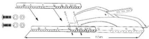
natural_image
Technical diagram of a mechanical device with a tool and hanging weights (no text or symbols)FIG. 15
natural_image
Simple diagram showing a hammer and string with a cross symbol, hanging from a hanging hook (no text or labels)
natural_image
Technical line drawing of a mechanical assembly with a lever and hanging weights (no text or symbols)
ADVERTIMIENTO
natural_image
Pure mechanical diagram showing a lever and fulcrum with no text or symbolsnatural_image
Technical line drawing of a structural support frame with diagonal bracing (no text or symbols)natural_image
Illustration of a person standing beside a window with a small object on the wall (no text or symbols)natural_image
Technical diagram of a mechanical device with a tool and hanging weights (no text or symbols)IMAG. 15


natural_image
Simple line drawing of a pendulum hanging from a horizontal beam, with a cross symbol indicating a mechanical or electrical component (no text or symbols present)
natural_image
Technical line drawing of a mechanical assembly with a lever and pulley (no text or symbols)