DUN461W - Hedge trimmers MAKITA - Free user manual and instructions
Find the device manual for free DUN461W MAKITA in PDF.
Download the instructions for your Hedge trimmers in PDF format for free! Find your manual DUN461W - MAKITA and take your electronic device back in hand. On this page are published all the documents necessary for the use of your device. DUN461W by MAKITA.
USER MANUAL DUN461W MAKITA
- Specicationsmaydierfromcountrytocountry.
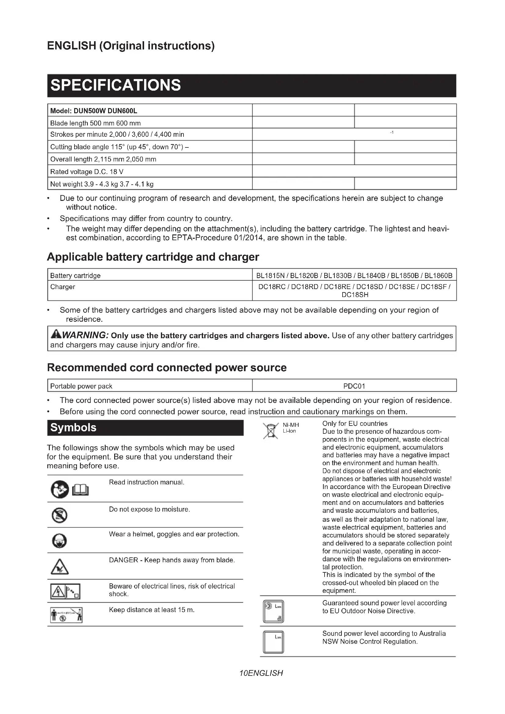
- Theweightmaydierdependingontheattachment(s),includingthebatterycartridge.Thelightestandheavi- est combination, according to EPTA-Procedure 01/2014, are shown in the table. Applicable battery cartridge and charger Batterycartridge BL1815N / BL1820B / BL1830B / BL1840B / BL1850B / BL1860B Charger DC18RC / DC18RD / DC18RE / DC18SD / DC18SE / DC18SF / DC18SH
- Someofthebatterycartridgesandchargerslistedabovemaynotbeavailabledependingonyourregionof residence.
WARNING: Only use the battery cartridges and chargers listed above.Useofanyotherbatterycartridges
- Beforeusingthecordconnectedpowersource,readinstructionandcautionarymarkingsonthem. Symbols Thefollowingsshowthesymbolswhichmaybeused fortheequipment.Besurethatyouunderstandtheir meaning before use. Read instruction manual. Do not expose to moisture. Wear a helmet, goggles and ear protection. DANGER-Keephandsawayfromblade. Beware of electrical lines, risk of electrical shock. Keep distance at least 15 m. Ni-MH Li-ion OnlyforEUcountries Due to the presence of hazardous com- ponents in the equipment, waste electrical and electronic equipment, accumulators andbatteriesmayhaveanegativeimpact on the environment and human health. Do not dispose of electrical and electronic appliances or batteries with household waste! In accordance with the European Directive on waste electrical and electronic equip- ment and on accumulators and batteries and waste accumulators and batteries, as well as their adaptation to national law, waste electrical equipment, batteries and accumulatorsshouldbestoredseparately and delivered to a separate collection point for municipal waste, operating in accor- dance with the regulations on environmen- tal protection. Thisisindicatedbythesymbolofthe crossed-out wheeled bin placed on the equipment. Guaranteed sound power level according to EU Outdoor Noise Directive. Sound power level according to Australia NSW Noise Control Regulation.11 ENGLISH Intended use The tool is intended for trimming hedges. Noise ThetypicalA-weightednoiseleveldeterminedaccord- ing to EN62841-4-2: Model DUN500W Sound pressure level (L
) : 93.5 dB (A) Uncertainty(K):3dB(A) NOTE: The declared noise emission value(s) has been measured in accordance with a standard test methodandmaybeusedforcomparingonetoolwith another. NOTE: The declared noise emission value(s) mayalsobeusedinapreliminaryassessmentof exposure.
WARNING: Wear ear protection.
WARNING: The noise emission during actual
use of the power tool can dier from the declared value(s) depending on the ways in which the tool is used especially what kind of workpiece is processed.
WARNING: Be sure to identify safety mea-
sures to protect the operator that are based on an estimation of exposure in the actual conditions of use (taking account of all parts of the operating cycle such as the times when the tool is switched o and when it is running idle in addition to the trigger time). Vibration Applicable standard : EN62841-4-2 Model Left hand (Front grip / Handle) Right hand (Rear grip)
(m/s ) UncertaintyK (m/s
(m/s ) UncertaintyK (m/s
DUN500W 4.7 1.52.5 m/s or less DUN600L 3.8 1.5 2.7 1.5 NOTE: The declared vibration total value(s) has been measured in accordance with a standard test method and maybeusedforcomparingonetoolwithanother. NOTE:Thedeclaredvibrationtotalvalue(s)mayalsobeusedinapreliminaryassessmentofexposure.
WARNING: The vibration emission during actual use of the power tool can dier from the declared
value(s) depending on the ways in which the tool is used especially what kind of workpiece is processed.
WARNING: Be sure to identify safety measures to protect the operator that are based on an estimation
of exposure in the actual conditions of use (taking account of all parts of the operating cycle such as the times when the tool is switched o and when it is running idle in addition to the trigger time). EC Declaration of Conformity For European countries only TheECdeclarationofconformityisincludedasAnnexA to this instruction manual. SAFETY WARNINGS General power tool safety warnings
WARNING: Read all safety warnings, instruc-
tions, illustrations and specications provided with this power tool. Failure to follow all instructions listedbelowmayresultinelectricshock,reand/or seriousinjury. Save all warnings and instruc- tions for future reference. Theterm"powertool"inthewarningsreferstoyour mains-operated(corded)powertoolorbattery-operated (cordless) power tool. Cordless Pole Hedge Trimmer Safety Warnings
1. Keep all parts of the body away from the blade.
Do not remove cut material or hold material to be cut when blades are moving. Blades continuetomoveaftertheswitchisturnedo.A moment of inattention while operating the hedge trimmermayresultinseriouspersonalinjury.
2. Carry the hedge trimmer by the handle with the
blade stopped and taking care not to operate any power switch.Propercarryingofthehedge trimmer will decrease the risk of inadvertent start- ingandresultantpersonalinjuryfromtheblades.12 ENGLISH
3. When transporting or storing the hedge trim-
mer, always t the blade cover. Proper handling of the hedge trimmer will decrease the risk of personalinjuryfromtheblades.
4. When clearing jammed material or servicing
the unit, make sure all power switches are o and the battery pack is removed or discon- nected. Unexpected actuation of the hedge trim- merwhileclearingjammedmaterialorservicing mayresultinseriouspersonalinjury.
5. Hold the hedge trimmer by insulated gripping
surfaces only, because the blade may contact hidden wiring. Blades contacting a "live" wire maymakeexposedmetalpartsofthehedgetrim- mer "live" and could give the operator an electric shock.
6. Keep all power cords and cables away from
cutting area.Powercordsorcablesmaybehid- deninhedgesorbushesandcanbeaccidentally cutbytheblade.
7. Do not use the hedge trimmer in bad weather
conditions, especially when there is a risk of lightning. This decreases the risk of being struck bylightning.
8. To reduce the risk of electrocution, never use
the pole hedge trimmer near any electrical power lines. Contact with or use near power lines maycauseseriousinjuryorelectricshockresult- ing in death.
9. Always use two hands when operating the pole
hedge trimmer. Hold the pole hedge trimmer with both hands to avoid loss of control.
10. Always use head protection when operating
the pole hedge trimmer overhead. Falling debris canresultinseriouspersonalinjury. Additional Safety Instructions Preparation
1. THIS HEDGE TRIMMER CAN CAUSE SERIOUS
INJURIES. Read the instructions carefully for the correct handling, preparation, main- tenance, starting and stopping of the tool. Become familiar with all controls and the proper use of the tool.
2. Check the hedges and bushes for foreign
objects, such as wire fences or hidden wiring before operating the tool.
3. The tool must not be used by children or
young persons under 18 years of age. Young personsover16yearsofagemaybeexempted fromthisrestrictioniftheyareundergoingtraining under the supervision of an expert.
4. In the event of an emergency, switch o
the tool and remove the battery cartridge immediately.
5. DANGER - Keep hands away from blade.
Contact with blade will result in serious personal injury.
6. Only use with handle and guard properly
assembled to the tool. The use of the tool withouttheproperguardorhandleprovidedmay resultinseriouspersonalinjury.
7. First-time users should have an experienced
user show them how to use the tool.
8. Before operation, examine the work area for
wire fences, stones, or other solid objects. They can damage the blades.
Use the tool only if you are in good physical condition.Ifyouaretired,yourattentionwillbe reduced.Beespeciallycarefulattheendofawork- ingday.Performallworkcalmlyandcarefully.The user is responsible for all damages to third parties.
10. Before starting work, check to make sure that
the tool is in good and safe working order. Ensure guards are tted properly. The tool must not be used unless fully assembled.
11. Avoid dangerous environment. Don't use the
tool in damp or wet locations or expose it to rain. Water entering the tool will increase the risk of electric shock. Personal protective equipment
1. Work gloves of stout leather are part of the
basic equipment of the tool and must always be worn when working with it. Also wear sturdy shoes with anti-skid soles.
2. Wear ear protection such as ear mus to pre-
3. Wear protective goggles, safety helmet and
protective gloves to protect yourself from ying debris or falling objects.
4. When touching blades or adjusting the blade
angle, wear protective gloves. Blades can cut barehandsseverely. Operation
1. Always use two hands to operate the tool tted
with two handles. Using one hand could cause lossofcontrolandresultinseriouspersonalinjury.
2. While operating the tool, always ensure that
the operating position is safe and secure. Overreaching with the tool, particularly from a ladder, is extremely dangerous. Do not work from anything wobbly or inrm.
3. Do not simultaneously wear multiple belt har-
nesses and/or shoulder harnesses when oper- ating the tool.
4. During operation, keep bystanders or animals
at least 15 m away from the tool. Stop the tool as soon as someone approaches.
5. If cutting tool strikes any object or the tool
starts making unusual noise or vibration, switch o the tool and remove the battery car- tridge immediately and allow the tool to stop. And then take the following steps:
- check for, and tighten, any loose parts
- have any damaged parts replaced or repaired with genuine spare parts.
6. Only use the tool for its intended purpose. Do
not use the tool for any other purpose.
7. Switch o the tool and remove the battery
- cleaning or when clearing a blockage,
- checking, carrying out maintenance or working on the tool,
- adjusting the working position of the shear blades,
- leaving the tool unattended.13 ENGLISH
8. Ensure that the tool is correctly located in a
designated working position before starting the tool.
9. Do not operate the tool with a damaged or
excessively worn shear blades.
10. Always ensure that all handles and guards
are tted when using the tool. Never attempt to use an incomplete tool or one tted with an unauthorized modication.
11. Always be aware of your surroundings and
stay alert for possible hazards of which you may not be aware due to the noise of the tool.
12. Be careful not to accidentally contact a metal
fence or other hard objects during operation. Thebladewillbreakandmaycauseseriousinjury.
13. Avoid unintentional starting. Do not carry the
tool when the battery cartridge is installed and with nger on the switch. Make sure that the switch is o when installing the battery cartridge.
14. Do not grasp the exposed cutting blades or
cutting edges when picking up or holding the tool.
15. Do not force the tool.Itwilldothejobbetterand
withlesslikelihoodofariskofinjuryattheratefor which it was designed.
16. Do not use the tool in the rain or in wet or
very damp conditions. The electric motor is not waterproof.
17. Hold the tool rmly when using the tool.
18. Do not operate the tool at no-load
19. Before checking the shear blades, taking care
of faults, or removing foreign objects caught in the shear blades, always switch o the tool and remove the battery cartridge.
21. If the blades stop moving due to the stuck of
foreign objects between the blades during operation, switch o the tool and remove the battery cartridge, and then remove the foreign objects using tools such as pliers. Removing theforeignobjectsbyhandmaycauseaninjury forthereasonthatthebladesmaymoveinreac- tiontoremovingtheforeignobjects. Maintenance and storage
1. When the tool is stopped for servicing, inspec-
tion or storage, switch o the tool and remove the battery cartridge, and make sure all mov- ing parts have come to a stop. Allow the tool to cool before making any inspections, adjust- ment, etc.
2. Always allow the tool to cool down before
3. When not in use, attach the blade cover to the
tool and store the tool indoors in dry, and high locked-up place, out of reach of children.
4. Maintain the tool with care. Keep cutting edge
sharp and clean for best performance and to reduce the risk of injury. Follow instructions for lubricating and changing accessories. Keep handles dry, clean, and free from oil and grease.
5. Check damaged parts. Before further use of
the tool, any part which is damaged should be carefully checked to determine that it will oper- ate properly and perform its intended function. Check for alignment of moving parts, binding of moving parts, breakage of parts, mounting and any other condition that may aect its operation. A guard or other part that is damaged shouldbeproperlyrepairedorreplacedbyyour authorized service center.
6. Use genuine spare parts only.
7. When moving the tool to another location,
including during work, always remove the battery cartridge and put the blade cover on the shear blades. Never carry or transport the tool with the blades running. Never grasp the blades with your hands.
8. Clean the tool and especially the shear blades
after use, and before putting the tool into stor- age for extended periods. Lightly oil the shear blades and put on the blade cover.
9. Do not dispose of the battery(ies) in a re. The
cell may explode. Check with local codes for possible special disposal instructions.
10. Do not open or mutilate the battery(ies).
Released electrolyte is corrosive and may cause damage to the eyes or skin. It may be toxic if swallowed.
11. Do not charge battery in rain, or in wet
locations. SAVE THESE INSTRUCTIONS.
WARNING: DO NOT let comfort or familiarity
with product (gained from repeated use) replace strict adherence to safety rules for the subject product. MISUSE or failure to follow the safety rules stated in this instruction manual may cause serious personal injury. Important safety instructions for battery cartridge
1. Before using battery cartridge, read all instruc-
tions and cautionary markings on (1) battery charger, (2) battery, and (3) product using battery.
2. Do not disassemble or tamper with the battery
cartridge.Itmayresultinare,excessiveheat, or explosion.
3. If operating time has become excessively
shorter, stop operating immediately. It may result in a risk of overheating, possible burns and even an explosion.
If electrolyte gets into your eyes, rinse them out with clear water and seek medical attention right away. It may result in loss of your eyesight.
5. Do not short the battery cartridge:
(1) Do not touch the terminals with any con- ductive material. (2) Avoid storing battery cartridge in a con- tainer with other metal objects such as nails, coins, etc. (3) Do not expose battery cartridge to water or rain.14 ENGLISH A battery short can cause a large current ow, overheating, possible burns and even a breakdown.
6. Do not store and use the tool and battery car-
tridge in locations where the temperature may reach or exceed 50 °C (122 °F).
7. Do not incinerate the battery cartridge even if
it is severely damaged or is completely worn out. The battery cartridge can explode in a re.
8. Do not nail, cut, crush, throw, drop the battery
cartridge, or hit against a hard object to the battery cartridge.Suchconductmayresultina re,excessiveheat,orexplosion.
9. Do not use a damaged battery.
10. The contained lithium-ion batteries are subject
to the Dangerous Goods Legislation require- ments. Forcommercialtransportse.g.bythirdparties, forwarding agents, special requirement on pack- aging and labeling must be observed. For preparation of the item being shipped, consult- ing an expert for hazardous material is required. Pleasealsoobservepossiblymoredetailed national regulations. Tapeormaskoopencontactsandpackupthe batteryinsuchamannerthatitcannotmove around in the packaging.
11. When disposing the battery cartridge, remove
it from the tool and dispose of it in a safe place. Follow your local regulations relating to disposal of battery.
12. Use the batteries only with the products
specied by Makita. Installing the batteries to non-compliantproductsmayresultinare,exces- siveheat,explosion,orleakofelectrolyte.
13. If the tool is not used for a long period of time,
the battery must be removed from the tool.
14. During and after use, the battery cartridge may
take on heat which can cause burns or low temperature burns. Pay attention to the han- dling of hot battery cartridges.
15. Do not touch the terminal of the tool imme-
diately after use as it may get hot enough to cause burns.
16. Do not allow chips, dust, or soil stuck into the
terminals, holes, and grooves of the battery cartridge.Itmaycauseheating,catchingre, burstandmalfunctionofthetoolorbatterycar- tridge,resultinginburnsorpersonalinjury.
17. Unless the tool supports the use near
high-voltage electrical power lines, do not use the battery cartridge near high-voltage electri- cal power lines.Itmayresultinamalfunctionor breakdownofthetoolorbatterycartridge.
18. Keep the battery away from children.
SAVE THESE INSTRUCTIONS. CAUTION: Only use genuine Makita batteries. Use of non-genuine Makita batteries, or batteries that havebeenaltered,mayresultinthebatterybursting causingres,personalinjuryanddamage.Itwill alsovoidtheMakitawarrantyfortheMakitatooland charger. Tips for maintaining maximum battery life
1. Charge the battery cartridge before completely
discharged. Always stop tool operation and charge the battery cartridge when you notice less tool power.
2. Never recharge a fully charged battery car-
tridge. Overcharging shortens the battery service life.
3. Charge the battery cartridge with room tem-
perature at 10 °C - 40 °C (50 °F - 104 °F). Let a hot battery cartridge cool down before charging it.
4. When not using the battery cartridge, remove
it from the tool or the charger.
5. Charge the battery cartridge if you do not use
it for a long period (more than six months). PARTS DESCRIPTION ►Fig.1 1 Head 2 Front grip 3 Hanger 4 Lever 5 Batterycartridge 6 Rear grip 7 Switch trigger 8 Slide sleeve 9 Shear blades 10 Speed indicator 11 Power lamp 12 Reverse button 13 Main power button 14 Handle - - - -15 ENGLISH FUNCTIONAL DESCRIPTION CAUTION: Always be sure that the tool is switched o and the battery cartridge is removed before adjusting or checking function on the tool. Installing or removing battery cartridge CAUTION: Always switch o the tool before installing or removing of the battery cartridge. CAUTION: Hold the tool and the battery car- tridge rmly when installing or removing battery cartridge.Failuretoholdthetoolandthebattery cartridgermlymaycausethemtoslipoyourhands andresultindamagetothetoolandbatterycartridge andapersonalinjury. ►Fig.2: 1. Red indicator 2. Button 3.Batterycartridge Toremovethebatterycartridge,slideitfromthetool while sliding the button on the front of the cartridge. Toinstallthebatterycartridge,alignthetongueonthe batterycartridgewiththegrooveinthehousingandslip itintoplace.Insertitallthewayuntilitlocksinplace withalittleclick.Ifyoucanseetheredindicatoras showninthegure,itisnotlockedcompletely. CAUTION: Always install the battery cartridge fully until the red indicator cannot be seen. If not, itmayaccidentallyfalloutofthetool,causinginjuryto youorsomeonearoundyou. CAUTION: Do not install the battery cartridge forcibly.Ifthecartridgedoesnotslideineasily,itis notbeinginsertedcorrectly. Indicating the remaining battery capacity Only for battery cartridges with the indicator ►Fig.3: 1. Indicator lamps 2. Check button Pressthecheckbuttononthebatterycartridgetoindi- catetheremainingbatterycapacity.Theindicatorlamps light up for a few seconds. Indicator lamps Remaining capacity Lighted O Blinking 75% to 100% 50% to 75% 25% to 50% 0% to 25% Charge the battery. Thebattery mayhave malfunctioned. NOTE: Depending on the conditions of use and the ambienttemperature,theindicationmaydierslightly fromtheactualcapacity. NOTE:Therst(farleft)indicatorlampwillblinkwhen thebatteryprotectionsystemworks. Tool / battery protection system Thetoolisequippedwithatool/batteryprotectionsys- tem.Thissystemautomaticallycutsopowertothe motortoextendtoolandbatterylife.Thetoolwillauto- maticallystopduringoperationifthetoolorbatteryis placed under one of the following conditions: Status Indicator lamps On O Blinking Overload Overheat Over discharge Overload protection Ifthetoolisoverloadedbyentangledbranchesorother debris, the indicators for "2" and "3" start blinking and thetoolautomaticallystops. Inthissituation,turnthetooloandstoptheapplication that caused the tool to become overloaded. Then turn the tool on to restart. NOTICE: Depending on the usage conditions, the tool is automatically turned o without any indication if the tool is overloaded by entangled branches or debris. In this case, switch o the tool and remove the battery cartridge, and then remove entangled branches or debris using tools such as pliers. After removing the branches or debris, install the battery cartridge and turn on the tool again. Overheat protection for tool or battery Therearetwotypesofoverheating;tooloverheating andbatteryoverheating.Whenthetooloverheating occurs,allspeedindicatorsblink.Whenthebattery overheating occurs, indicator for "1" blinks. Iftheoverheatingoccurs,thetoolstopsautomatically. Letthetooland/orbatterycooldownbeforeturningthe tool on again. Overdischarge protection Whenthebatterycapacitybecomeslow,thetoolstops automaticallyandindicatorfor"1"blinks. If the tool does not operate even when the switches are operated,removethebatteryfromthetoolandcharge thebattery.16 ENGLISH Power switch action
WARNING: For your safety, this tool is
equipped with lever which prevents the tool from unintended starting. NEVER use the tool if it runs when you simply pull the switch trigger without pressing the lever. Return the tool to our autho- rized service center for proper repairs BEFORE further usage.
WARNING: NEVER tape down or defeat pur-
pose and function of lever.
WARNING: Before installing the battery
cartridge on the tool, always check to see that the switch trigger and lever actuate properly and return to the "OFF" position when released. Operating a tool with a switch that does not actuate properlycanleadtolossofcontrolandseriousper- sonalinjury. CAUTION: Never put your nger on the switch when carrying.Thetoolmaystartuninten- tionallyandcauseinjury. NOTICE: Do not pull the switch trigger hard without pressing the lever. This can cause switch breakage. Press the main power button to turn on the tool. The power lamp lights up when the tool is turned on. To turn othetool,pressandholdthemainpowerbutton.The powerlampgoesowhenthetoolisturnedo. ►Fig.4: 1. Power lamp 2. Main power button NOTE:Thetoolisautomaticallyturnedoifthetoolis not operated for a certain period. Topreventtheswitchtriggerfrombeingaccidentally pulled, a lever is provided. To start the tool, pull the switch trigger while pressing the lever. Release the switch trigger to stop. ►Fig.5: 1. Lever 2. Switch trigger Speed adjusting Youcanadjustthetoolspeedbypressingthemain powerbutton.Eachtimeyoupressthemainpower button, the level of speed changes. ►Fig.6: 1. Speed indicator 2. Main power button Indicator Mode Stroke speed High 4,400 min
Reverse button for debris removal
WARNING: If the entangled branches or
debris cannot be removed by the reverse func- tion, switch o the tool and remove the bat- tery cartridge, and then remove the entangled branches or debris using tools such as pliers. Failuretoswitchothetoolandremovethebat- terycartridgemayresultinseriouspersonalinjury from accidental start-up. Removing the entangled branchesordebrisbyhandmaycauseaninjury, sincetheshearbladesmaymoveinreactionto removing them. This tool has a reverse button to change the direction ofshearbladesmovement.Itisonlyforremoving branches and debris entangled in the tool. To reverse the shear blades movement, press the reverse button when the shear blades have stopped, and then pull the switch trigger while pressing the lever. The power lamp starts blinking, and the shear blades move in reverse direction. When entangled branches and debris are removed, the tool returns to the regular movement and the power lamp stops blinking and lights up. ►Fig.7: 1. Power lamp 2. Reverse button NOTE: If the entangled branches or debris cannot be removed, release the switch trigger, then press the reverse button, and then pull the switch trigger until theyareremoved. NOTE:Ifyoutapthereversebuttonwhiletheshear blades are still moving, the tool comes to stop and to bereadyforreversemovement. Adjusting the cutting angle CAUTION: Always be sure that the tool is switched o before folding or unfolding the head. CAUTION: When folding the head for carrying the tool or after using the tool, be sure to attach the blade cover before folding the head. CAUTION: When folding the head, be careful not to pinch your ngers between the head and the slide sleeve. For DUN500W Theangleoftheheadcanbeadjustedin6steps.To change the angle of the head, follow the steps below.
1. Hold the head and the slide sleeve as shown in
thegure. ►Fig.8: 1. Head 2. Slide sleeve
2. Move the head while holding down the slide
sleeve, and then release the slide sleeve.
3. Movetheheadslightlyuntilitislockedwithaclick.
NOTE:Makesurethattheheadissecurelylocked before operating the tool.17 ENGLISH Hex wrench storage For DUN600L When not in use, store the hex wrench as illustrated to keep it from being lost. ►Fig.9: 1. Handle 2. Hex wrench ASSEMBLY CAUTION: Always be sure that the tool is switched o and the battery cartridge is removed before carrying out any work on the tool. CAUTION: When replacing the shear blades, always wear gloves so that your hands do not directly contact the blades. Installing the handle For DUN600L
1. Attach the upper and lower clamps on the damper.
2. Putthehandleontheupperclampandxitwith
bolts as illustrated. ►Fig.10: 1. Bolt 2. Handle 3. Upper clamp 4. Damper
Installing or removing the shear blades CAUTION: Attach the blade cover before removing or installing the shear blades. NOTICE: When replacing the shear blades, do not wipe o grease from the gear and crank. NOTICE: For DUN500W Do not install 600 mm shear blades to your tool. If600mmshearbladesareinstalledtothetool,you cannot fold the head of the tool. NOTE: For DUN500W Before installing or removing the shear blades, unfold the head of the tool so that the head is straight to the toolbody.
1. Place the tool upside down, and then remove 6
bolts. ►Fig.11: 1. Bolt
2. Remove the cover, gasket, plate A, and plate B.
►Fig.12: 1. Cover 2. Gasket 3. Plate A 4. Plate B NOTE:Thegasketorplatesmayremainonthecover.
3. Remove the rod and the bearing.
►Fig.13: 1. Rod 2. Bearing NOTE:Therodorbearingmayremainonthecover.
4. Remove 2 bolts, 2 sleeves, and the felt pad, and
then remove the shear blades. ►Fig.14: 1. Felt pad 2. Bolt 3. Sleeve 4. Shear blades NOTICE: Be careful not to lose the bolts.
5. Remove the blade cover, and then attach it to the
the alignment line. ►Fig.16: 1. Hole 2. Alignment line
7. Aligntheprotrusionsontheshearbladesvertically
at the same position. ►Fig.17: 1. Protrusion
8. Attach the felt pad to the shear blades.
►Fig.18: 1. Felt pad
9. Insert the protrusion on the shear blades to the
hole on the rod, then align the position of the felt pad with the holes on the tool, and then attach the sleeves. ►Fig.19: 1. Felt pad 2. Protrusion 3. Hole 4. Sleeve NOTICE: Apply a small amount of grease to the inner periphery of the hole of the rod. NOTICE: Be careful not to lose the sleeves.
10. Align the holes on the sleeves and the shear
blades with the holes on the tool, and then tighten 2 boltstoxtheshearblades. ►Fig.20: 1. Bolt 2. Hole
11. Attach the bearing and the rod.
►Fig.21: 1. Rod 2. Small hole 3. Bearing NOTICE: Apply a small amount of grease to the inner periphery of the small hole of the rod. NOTICE: Make sure that the protrusion on the shear blades ts in the small hole on the rod.
12. Attach plate B, plate A, and the gasket.
►Fig.22: 1. Gasket 2. Plate A 3. Plate B
13. Align the hole in the plate with the protrusion on
theshearbladessothattheprotrusiontsinthehole. ►Fig.23: 1. Protrusion 2. Plate
14. Attach the cover, and then tighten 6 bolts.
►Fig.24: 1. Cover 2. Bolt NOTICE: If the shear blades do not move smoothly, the shear blades are not engaged with the rods properly. Install the shear blades again. NOTICE: If the parts other than the shear blades such as the rods are worn out, ask Makita Authorized Service Centers for parts replacement or repairs.18 ENGLISH Installing or removing the chip receiver Optional accessory CAUTION: When installing or removing the chip receiver, always wear gloves so that your hands do not directly contact the shear blades. NOTICE: The blade cover cannot be installed if the chip receiver is installed on the tool. Before carrying or storing the tool, uninstall the chip receiver, and then install the blade cover to avoid blade exposure. NOTICE: Be sure to remove the blade cover before installing the chip receiver. The chip receiver gathers discarded leaves and makes clean-up afterward much easier. It can be installed on either side of the tool. Type1 To install the chip receiver, put and press the chip receiverontotheshearbladessothatthehookstinto the grooves on the shear blades. ►Fig.25: 1. Hook ►Fig.26: 1. Hook NOTICE: Make sure that the chip receiver does not overlap the branch catcher. ►Fig.27: 1. Branch catcher To remove the chip receiver, press the levers on both sides to release the hooks. ►Fig.28: 1. Lever Type2
1. Hook the claws of the chip receiver to the shear
blades. ►Fig.29: 1. Claw
2. Align the holes on the chip receiver with the
screws on the shear blades, and then attach the chip receivertotheshearbladessecurely. ►Fig.30: 1. Hole NOTICE: Make sure that the chip receiver does not overlap the branch catcher. ►Fig.31: 1. Branch catcher To remove the chip receiver, press the levers to release the claws. ►Fig.32: 1. Lever NOTICE: Never try to remove the chip receiver by an excessive force with its hooks locked in the grooves of the shear blades. OPERATION Attaching the shoulder harness Optional accessory for DUN500W CAUTION: Before operation, make sure that the shoulder harness is properly attached to the hanger on the tool. CAUTION: When you use the tool in combi- nation of the backpack-type power supply such as portable power pack, do not use the shoulder harness included in the tool package, but use the hanging band recommended by Makita. Ifyouputontheshoulderharnessincludedinthe tool package and the shoulder harness of the back- pack-typepowersupplyatthesametime,removing thetoolorbackpack-typepowersupplyisdicultin caseofanemergency,anditmaycauseanaccident orinjury.Fortherecommendedhangingband,ask Makita Authorized Service Centers. NOTE: Use the shoulder harness attached to the tool. Beforeoperation,adjusttheshoulderharnessaccord- ing to the user size to prevent fatigue.
2. Clasp the hook on the shoulder harness to the
working position. ►Fig.35 The shoulder harness features a means of quick release. Simplysqueezethesidesofthebuckletoreleasethe tool from the shoulder harness. ►Fig.36: 1. Buckle Operating the tool
WARNING: Do not use the tool near any
electrical power lines. Contacting with power lines orusingthetoolnearpowerlinesmaycauseserious injuryorelectricshockresultingindeath.
WARNING: Keep hands away from shear
WARNING: Be extremely careful to maintain
control of the tool at all times. Do not allow the tool to be deected toward you or anyone in the work vicinity. Failure to keep control of the tool couldresultinseriousinjurytothebystanderandthe operator.19 ENGLISH CAUTION: Avoid operating the tool in very hot weather as much as practicable. When operat- ing the tool, be careful of your physical condition. CAUTION: Be careful not to accidentally contact a metal fence or other hard objects while trimming.Theshearbladesmaybreakandcause aninjury. CAUTION: Be careful not to allow the shear blades to contact the ground.Thetoolmayrecoil andcauseaninjury. CAUTION: Overreaching with a hedge trim- mer, particularly from a ladder, is extremely dangerous.Donotworkwhilestandingonanything wobblyorinrm. NOTICE: Do not attempt to cut branches thicker than 10 mm in diameter with the tool. Cut branches to 10 cm lower than the cutting height using branch cutters before using the tool. ►Fig.37: (1) Cutting height (2) 10 cm NOTICE: Do not cut down dead trees or similar hard objects.Doingsomaydamagethetool. NOTICE: Do not trim the grass or weeds while using the shear blades.Theshearbladesmay become tangled in the grass or weeds. Hold the tool with both hands. For DUN500W ►Fig.38 For DUN600L ►Fig.39 Pull the switch trigger while pressing the lever, and then move the tool forward. ►Fig.40 For basic operation, tilt the shear blades toward the trimmingdirectionandmoveitcalmlyandslowlyatthe speed rate of 3 to 4 seconds per meter. ►Fig.41 Tocutahedgesideevenly,cutfromthebottomtotop. ►Fig.42 When trimming to make a round shape (trimming box- wood or rhododendron, etc.), trim from the root to the topforabeautifulnish. ►Fig.43 If the chip receiver is attached to the shear blades, it gathers discarded leaves and makes clean-up after- ward much easier. ►Fig.44 MAINTENANCE CAUTION: Always be sure that the tool is switched o and the battery cartridge is removed before attempting to perform inspection or maintenance. CAUTION: When inspecting or maintaining the tool, always put the tool down. Assembling or adjustingthetoolinanuprightpositionmayresultin seriousinjury. To maintain product SAFETY and RELIABILITY, repairs,anyothermaintenanceoradjustmentshould beperformedbyMakitaAuthorizedorFactoryService Centers,alwaysusingMakitareplacementparts. Cleaning the tool Cleanthetoolbywipingodustwithadryclothorone dippedinsoapywaterandwrungout. NOTICE: Never use gasoline, benzine, thinner, alcohol or the like. Discoloration, deformation or cracks may result. Shear blade maintenance Before the operation or once per hour during operation, applylow-viscosityoil(machineoil,orspray-typelubri- cating oil) to the shear blades. ►Fig.45 After operation, remove dust from both sides of the shearbladeswithawiredbrush,wipeitowithacloth andthenapplylow-viscosityoil(machineoil,orspray- typelubricatingoil)totheshearblades. ►Fig.46 NOTICE: Do not wash the shear blades in water. Doingsomaycauserustordamagetothetool. NOTICE: Dirt and corrosion cause excessive blade friction and shorten the operating time per battery charge. Storage Attach the blade cover to the shear blades so that the blades are not exposed. Store the tool out of the reach of children. Store the tool in a place not exposed to moisture or rain. Grinding the shear blades NOTICE: If the shear blades have considerably deformed by grinding, replace the shear blades with new ones.
1. Installthebatterycartridgetothetool.
2. Turn on and start the tool so that the upper blade
from the tool.20 ENGLISH
4. Remove the screw, and then remove the branch
bladefrom3directionswiththele. ►Fig.49: (1) File (2) 45° CAUTION: Before grinding the shear blades, make sure that the tool is switched o and the battery cartridge is removed from the tool.
6. Place the tool upside down, and then remove the
burrs from the shear blades with the dressing stone. ►Fig.50: 1. Dressing stone
8. Return the tool to normal position, and then
remove the burrs from the shear blades with the dress- ing stone.
1. Remove the bolt from the hole for lubrication.
2. Remove the cap from the grease vessel. Align the
outlet of the grease vessel with the hole on the cover, and then press the outlet of the grease vessel onto the hole. ►Fig.52: 1. Grease vessel 2. Hole
TROUBLESHOOTING Beforeaskingforrepairs,conductyourowninspectionrst.Ifyoundaproblemthatisnotexplainedinthemanual, donotattempttodismantlethetool.Instead,askMakitaAuthorizedServiceCenters,alwaysusingMakitareplace- ment parts for repairs. State of abnormality Probable cause (malfunction) Remedy Motor does not run. Batterycartridgeisnotinstalled. Installthebatterycartridge. Batteryproblem(undervoltage) Rechargethebattery.Ifrechargingisnoteective, replacebattery. Thedrivesystemdoesnotwork correctly. Askyourlocalauthorizedservicecenterforrepair. Motor stops running after a little use. Battery'schargelevelislow. Rechargethebattery.Ifrechargingisnoteective, replacebattery. Overheating. Stop using of tool to allow it to cool down. Tool does not reach maximum RPM. Batteryisinstalledimproperly. Installthebatterycartridgeasdescribedinthis manual. Batterypowerisdropping. Rechargethebattery.Ifrechargingisnoteective, replacebattery. Thedrivesystemdoesnotwork correctly. Askyourlocalauthorizedservicecenterforrepair. Shear blades do not move: stopthemachineimmediately! Inappropriate angle of shear blades. Makesurethattheheadisproperlyxedinthe operational angle. Foreignobjectsarecaughtbetweenthe shear blades.
1. Use the reverse button.
2.Switchothetoolandremovethebatterycar- tridge,andthenremovetheforeignobjectsusing tools such as pliers. Thedrivesystemdoesnotwork correctly. Askyourlocalauthorizedservicecenterforrepair. Abnormal vibration: stopthemachineimmediately! Shear blades are broken, bent or worn. Replace the shear blades. Thedrivesystemdoesnotwork correctly. Askyourlocalauthorizedservicecenterforrepair. Shear blades and motor cannot stop: Removethebatteryimmediately! Electric malfunction. Removethebatteryandaskyourlocalauthorized service center for repair.21 ENGLISH OPTIONAL ACCESSORIES CAUTION: These accessories or attachments are recommended for use with your Makita tool specied in this manual.Theuseofanyother accessories or attachments might present a risk of injurytopersons.Onlyuseaccessoryorattachment for its stated purpose. Ifyouneedanyassistanceformoredetailsregard- ingtheseaccessories,askyourlocalMakitaService Center.