UH006GZ - Hedge trimmers MAKITA - Free user manual and instructions
Find the device manual for free UH006GZ MAKITA in PDF.
User questions about UH006GZ MAKITA
0 question about this device. Answer the ones you know or ask your own.
Ask a new question about this device
Download the instructions for your Hedge trimmers in PDF format for free! Find your manual UH006GZ - MAKITA and take your electronic device back in hand. On this page are published all the documents necessary for the use of your device. UH006GZ by MAKITA.
USER MANUAL UH006GZ MAKITA
- Due to our continuing program of research and development, the specifications herein are subject to change without notice.
- Specifications may differ from country to country.
1: Weight without any accessories or battery cartridge(s)
2: The weight may differ depending on the attachment(s), including the battery cartridge. The lightest and heaviest combinations, according to EPTA-Procedure 01/2014, are shown in the table.
Applicable battery cartridge and charger
| Battery cartridge | BL4020* / BL4025* / BL4040* / BL4040F* / BL4050F / BL4080F * : Recommended battery |
| Charger | DC40RA / DC40RB / DC40RC / DC40WA |
Some of the battery cartridges and chargers listed above may not be available depending on your region of residence.

WARNING: Only use the battery cartridges and chargers listed above. Use of any other battery cartridges and chargers may cause injury and/or fire.
Recommended cord connected power source
Portable power pack
PDC01/PDC1200/PDC1500
The cord connected power source(s) listed above may not be available depending on your region of residence.
Before using the cord connected power source, read instruction and cautionary markings on them.
Symbols
The followings show the symbols which may be used for the equipment. Be sure that you understand their meaning before use.


Read instruction manual.

Wear eye protection.

Wear eye and ear protection.

DANGER - Keep hands away from blade.
Due to the presence of hazardous components in the equipment, waste electrical and electronic equipment, accumulators and batteries may have a negative impact on the environment and human health. Do not dispose of electrical and electronic appliances or batteries with household waste! In accordance with the European Directive on waste electrical and electronic equipment and on accumulators and batteries and waste accumulators and batteries, as well as their adaptation to national law, waste electrical equipment, batteries and accumulators should be stored separately and delivered to a separate collection point for municipal waste, operating in accordance with the regulations on environmental protection. This is indicated by the symbol of the crossed-out wheeled bin placed on the equipment.
Intended use
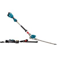
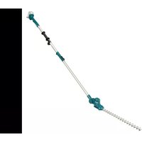
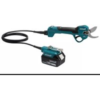
The tool is intended for trimming hedges.
Noise
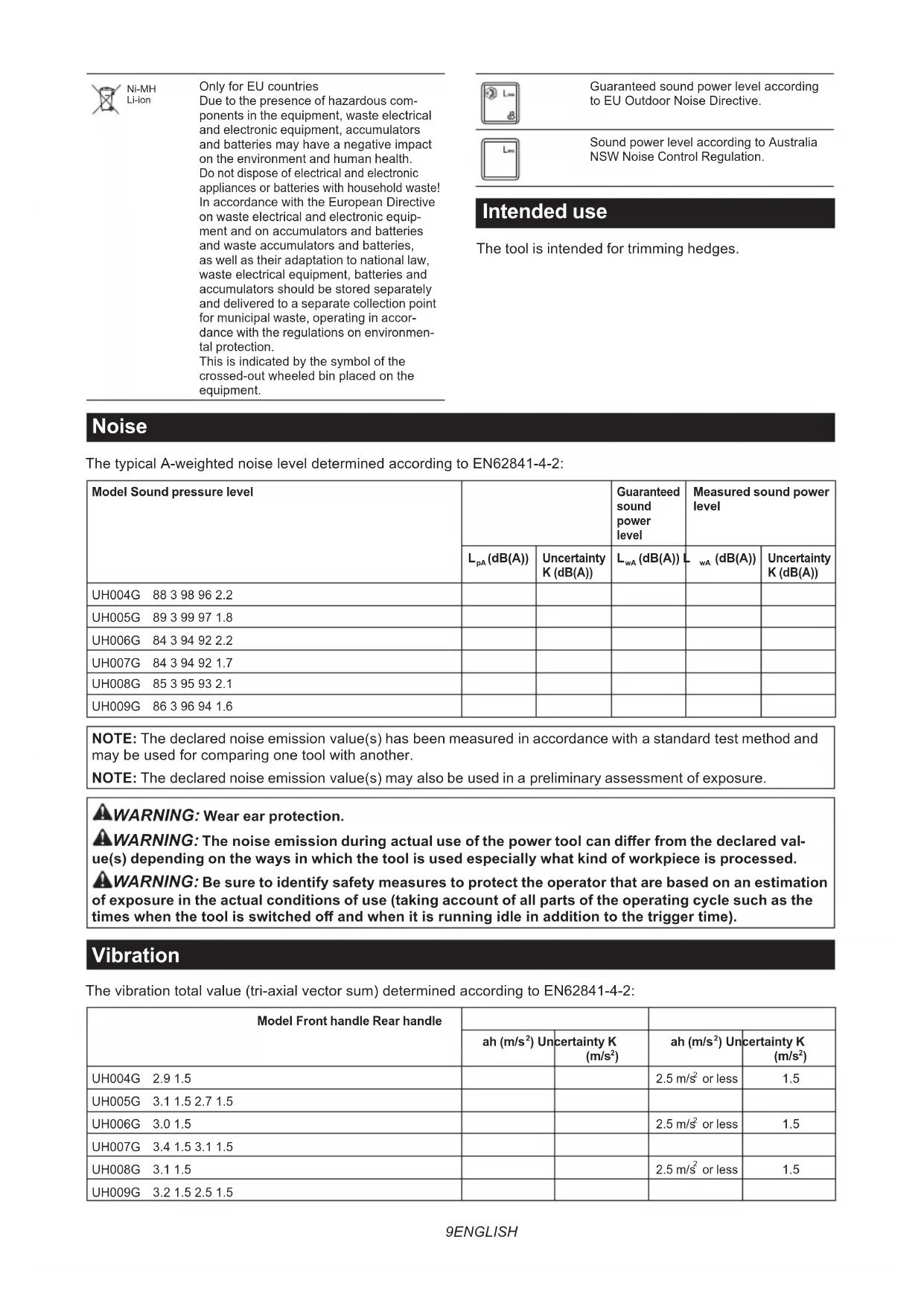
The typical A-weighted noise level determined according to EN62841-4-2:
| Model Sound pressure level | Guaranteed sound power level | Measured sound power level | |||
| LpA(dB(A)) | Uncertainty K (dB(A)) | LwA(dB(A)) | LwA(dB(A)) | Uncertainty K (dB(A)) | |
| UH004G 88 3 98 96 2.2 | |||||
| UH005G 89 3 99 97 1.8 | |||||
| UH006G 84 3 94 92 2.2 | |||||
| UH007G 84 3 94 92 1.7 | |||||
| UH008G 85 3 95 93 2.1 | |||||
| UH009G 86 3 96 94 1.6 | |||||
NOTE: The declared noise emission value(s) has been measured in accordance with a standard test method and may be used for comparing one tool with another.
NOTE: The declared noise emission value(s) may also be used in a preliminary assessment of exposure.
WARNING: Wear ear protection.
WARNING: The noise emission during actual use of the power tool can differ from the declared value(s) depending on the ways in which the tool is used especially what kind of workpiece is processed.
WARNING: Be sure to identify safety measures to protect the operator that are based on an estimation of exposure in the actual conditions of use (taking account of all parts of the operating cycle such as the times when the tool is switched off and when it is running idle in addition to the trigger time).
Vibration
The vibration total value (tri-axial vector sum) determined according to EN62841-4-2:
| Model Front handle Rear handle | ||||
| ah (m/s2) Uncertainty K (m/s2) | ah (m/s2) Uncertainty K (m/s2) | |||
| UH004G 2.9 1.5 | 2.5 m/s2or less | 1.5 | ||
| UH005G 3.1 1.5 2.7 1.5 | ||||
| UH006G 3.0 1.5 | 2.5 m/s2or less | 1.5 | ||
| UH007G 3.4 1.5 3.1 1.5 | ||||
| UH008G 3.1 1.5 | 2.5 m/s2or less | 1.5 | ||
| UH009G 3.2 1.5 2.5 1.5 | ||||
NOTE: The declared vibration total value(s) has been measured in accordance with a standard test method and may be used for comparing one tool with another.
NOTE: The declared vibration total value(s) may also be used in a preliminary assessment of exposure.
WARNING: The vibration emission during actual use of the power tool can differ from the declared value(s) depending on the ways in which the tool is used especially what kind of workpiece is processed.
WARNING: Be sure to identify safety measures to protect the operator that are based on an estimation of exposure in the actual conditions of use (taking account of all parts of the operating cycle such as the times when the tool is switched off and when it is running idle in addition to the trigger time).
Declarations of Conformity
For European countries only
The Declarations of conformity are included in Annex A to this instruction manual.
SAFETYWARNINGS
General power tool safety warnings
WARNING Read all safety warnings, instructions, illustrations and specifications provided with this power tool. Failure to follow all instructions listed below may result in electric shock, fire and/or serious injury.
Save all warnings and instructions for future reference.
The term "power tool" in the warnings refers to your mains-operated (corded) power tool or battery-operated (cordless) power tool.
Cordless hedge trimmer safety warnings
- Do not use the hedge trimmer in bad weather conditions, especially when there is a risk of lightning. This decreases the risk of being struck by lightning.
- Keep all power cords and cables away from cutting area. Power cords or cables may be hidden in hedges or bushes and can be accidentally cut by the blade.
- Wear ear protection. Adequate protective equipment will reduce the risk of hearing loss.
- Hold the hedge trimmer by insulated gripping surfaces only, because the blade may contact hidden wiring. Blades contacting a "live" wire may make exposed metal parts of the hedge trimmer "live" and could give the operator an electric shock.
-
Keep all parts of the body away from the blade. Do not remove cut material or hold material to be cut when blades are moving. Blades continue to move after the switch is turned off. A moment of inattention while operating the hedge trimmer may result in serious personal injury.
-
When clearing jammed material or servicing the hedge trimmer, make sure all power switches are off and the battery pack is removed or disconnected. Unexpected actuation of the hedge trimmer while clearing jammed material or servicing may result in serious personal injury.
- Carry the hedge trimmer by the handle with the blade stopped and taking care not to operate any power switch. Proper carrying of the hedge trimmer will decrease the risk of inadvertent starting and resultant personal injury from the blades.
- When transporting or storing the hedge trimmer, always use the blade cover. Proper handling of the hedge trimmer will decrease the risk of personal injury from the blades.
Additional safety warnings
Preparation
- Check the hedges and bushes for foreign objects, such as wire fences or hidden wiring before operating the tool.
- The tool must not be used by children or young persons under 18 years of age. Young persons over 16 years of age may be exempted from this restriction if they are undergoing training under the supervision of an expert.
- First-time users should have an experienced user show them how to use the tool.
- Use the tool only if you are in good physical condition. If you are tired, your attention will be reduced. Be especially careful at the end of a working day. Perform all work calmly and carefully. The user is responsible for all damages to third parties.
- Never use the tool when under the influence of alcohol, drugs or medication.
- Work gloves of stout leather are part of the basic equipment of the tool and must always be worn when working with it. Also wear sturdy shoes with anti-skid soles.
- Before starting work check to make sure that the tool is in good and safe working order. Ensure guards are fitted properly. The tool must not be used unless fully assembled.
Operation
- Hold the tool firmly with both hands when using the tool.
-
The tool is intended to be used by the operator at ground level. Do not use the tool on ladders or any other unstable support.
-
DANGER - Keep hands away from blade.
Contact with blade will result in serious personal injury. - Do not use the tool in the rain or in wet or very damp conditions. The electric motor is not waterproof.
- Make sure you have a secure footing before starting operation.
- Do not operate the tool at no-load unnecessarily.
- Immediately switch off the tool and remove the battery cartridge if the shear blades should come into contact with a fence or other hard object. Check the blades for damage, and if damaged, replace the blades immediately.
- Before checking the shear blades, taking care of faults, or removing material caught in the shear blades, always switch off the tool and remove the battery cartridge.
- Never point the shear blades to yourself or others.
- If the blades stop moving due to the stuck of foreign objects between the blades during operation, switch off the tool and remove the battery cartridge, and then remove the foreign objects using tools such as pliers. Removing the foreign objects by hand may cause an injury for the reason that the blades may move in reaction to removing the foreign objects.
- Avoid dangerous environment. Don't use the tool in damp or wet locations or expose it to rain. Water entering the tool will increase the risk of electric shock.
- When you use the tool on muddy ground, wet slope, or slippery place, pay attention to your footing.
- Avoid working in poor environment where increased user fatigue is expected.
- Do not use the tool in bad weather where visibility is limited. Failure to do so may cause fall or incorrect operation due to low visibility.
- Do not submerge the tool into a puddle.
- Do not leave the tool unattended outdoors in the rain.
- When wet leaves or dirt adhere to the suction mouth (ventilation window) due to rain, remove them.
- Do not use the tool in the snow.
Electrical and battery safety
- Avoid dangerous environment. Don't use the tool in damp or wet locations or expose it to rain. Water entering the tool will increase the risk of electric shock.
- Do not dispose of the battery(ies) in a fire. The cell may explode. Check with local codes for possible special disposal instructions.
- Do not open or mutilate the battery(ies). Released electrolyte is corrosive and may cause damage to the eyes or skin. It may be toxic if swallowed.
- Do not charge battery in rain, or in wet locations.
-
Do not charge the battery outdoors.
-
Do not handle charger, including charger plug, and charger terminals with wet hands.
- Do not replace the battery with wet hands.
- Do not replace the battery in the rain.
- Do not wet the terminal of battery with liquid such as water, or submerge the battery. Do not leave the battery in the rain, nor charge, use, or store the battery in a damp or wet place. If the terminal gets wet or liquid enters inside of battery, the battery may be short circuited and there is a risk of overheat, fire, or explosion.
- After removing the battery from the tool or charger, be sure to attach the battery cover to the battery and store it in a dry place.
- If the battery cartridge gets wet, drain the water inside and then wipe it with a dry cloth. Dry the battery cartridge completely in a dry place before use.
Maintenance and storage
- Switch off the tool and remove the battery cartridge before doing any maintenance work.
- When moving the tool to another location, including during work, always remove the battery cartridge and put the blade cover on the shear blades. Never carry or transport the tool with the blades running. Never grasp the blades with your hands.
- Clean the tool and especially the shear blades after use, and before putting the tool into storage for extended periods. Lightly oil the blades and put on the blade cover.
- Store the tool with the blade cover on, in a dry room. Keep it out of reach of children. Never store the tool outdoors.
- Do not dispose of the battery(ies) in a fire. The cell may explode. Check with local codes for possible special disposal instructions.
- Do not open or mutilate the battery(ies). Released electrolyte is corrosive and may cause damage to the eyes or skin. It may be toxic if swallowed.
- Do not charge battery in rain, or in wet locations.
- Do not wash the tool with high pressure water.
- When washing the tool, do not let water enter the electrical mechanism such as battery, motor, and terminals.
- Perform inspection or maintenance in a place where rain can be avoided.
- After using the tool, remove the adhered dirt and dry the tool completely before storing. Depending on the season or the area, there is a risk of malfunction due to freezing.
- When storing the tool, avoid direct sunlight and rain, and store it in a place where it does not get hot or humid.
SAVE THESE INSTRUCTIONS.
WARNING: DO NOT let comfort or familiarity with product (gained from repeated use) replace strict adherence to safety rules for the subject product. MISUSE or failure to follow the safety rules stated in this instruction manual may cause serious personal injury.
Important safety instructions for battery cartridge
- Before using battery cartridge, read all instructions and cautionary markings on (1) battery charger, (2) battery, and (3) product using battery.
- Do not disassemble or tamper with the battery cartridge. It may result in a fire, excessive heat, or explosion.
- If operating time has become excessively shorter, stop operating immediately. It may result in a risk of overheating, possible burns and even an explosion.
- If electrolyte gets into your eyes, rinse them out with clear water and seek medical attention right away. It may result in loss of your eyesight.
- Do not short the battery cartridge:
(1) Do not touch the terminals with any conductive material.
(2) Avoid storing battery cartridge in a container with other metal objects such as nails, coins, etc.
(3) Do not expose battery cartridge to water or rain. A battery short can cause a large current flow, overheating, possible burns and even a breakdown.
- Do not store and use the tool and battery cartridge in locations where the temperature may reach or exceed 50^ (122^) .
- Do not incinerate the battery cartridge even if it is severely damaged or is completely worn out. The battery cartridge can explode in a fire.
- Do not nail, cut, crush, throw, drop the battery cartridge, or hit against a hard object to the battery cartridge. Such conduct may result in a fire, excessive heat, or explosion.
- Do not use a damaged battery.
- The contained lithium-ion batteries are subject to the Dangerous Goods Legislation requirements.
For commercial transports e.g. by third parties, forwarding agents, special requirement on packaging and labeling must be observed.
For preparation of the item being shipped, consulting an expert for hazardous material is required.
Please also observe possibly more detailed national regulations.
Tape or mask off open contacts and pack up the battery in such a manner that it cannot move around in the packaging.
- When disposing the battery cartridge, remove it from the tool and dispose of it in a safe place. Follow your local regulations relating to disposal of battery.
-
Use the batteries only with the products specified by Makita. Installing the batteries to non-compliant products may result in a fire, excessive heat, explosion, or leak of electrolyte.
-
If the tool is not used for a long period of time, the battery must be removed from the tool.
- During and after use, the battery cartridge may take on heat which can cause burns or low temperature burns. Pay attention to the handling of hot battery cartridges.
- Do not touch the terminal of the tool immediately after use as it may get hot enough to cause burns.
- Do not allow chips, dust, or soil stuck into the terminals, holes, and grooves of the battery cartridge. It may cause heating, catching fire, burst and malfunction of the tool or battery cartridge, resulting in burns or personal injury.
-
Unless the tool supports the use near high-voltage electrical power lines, do not use the battery cartridge near high-voltage electrical power lines. It may result in a malfunction or breakdown of the tool or battery cartridge.
-
Keep the battery away from children.
SAVE THESE INSTRUCTIONS.
CAUTION: Only use genuine Makita batteries. Use of non-genuine Makita batteries, or batteries that have been altered, may result in the battery bursting causing fires, personal injury and damage. It will also void the Makita warranty for the Makita tool and charger.
Tips for maintaining maximum battery life
- Charge the battery cartridge before completely discharged. Always stop tool operation and charge the battery cartridge when you notice less tool power.
- Never recharge a fully charged battery cartridge. Overcharging shortens the battery service life.
- Charge the battery cartridge with room temperature at 10^ - 40^ (50°F - 104°F). Let a hot battery cartridge cool down before charging it.
- When not using the battery cartridge, remove it from the tool or the charger.
- Charge the battery cartridge if you do not use it for a long period (more than six months).
FUNCTIONAL DESCRIPTION
CAUTION: Always be sure that the tool is switched off and the battery cartridge is removed before adjusting or checking function on the tool.
Installing or removing battery cartridge
CAUTION: Always switch off the tool before installing or removing of the battery cartridge.
CAUTION: Hold the tool and the battery cartridge firmly when installing or removing battery cartridge. Failure to hold the tool and the battery cartridge firmly may cause them to slip off your hands and result in damage to the tool and battery cartridge and a personal injury.
Fig.1: 1. Red indicator 2. Button 3. Battery cartridge
To remove the battery cartridge, slide it from the tool while sliding the button on the front of the cartridge.
To install the battery cartridge, align the tongue on the battery cartridge with the groove in the housing and slip it into place. Insert it all the way until it locks in place with a little click. If you can see the red indicator as shown in the figure, it is not locked completely.
CAUTION: Always install the battery cartridge fully until the red indicator cannot be seen. If not, it may accidentally fall out of the tool, causing injury to you or someone around you.
CAUTION: Do not install the battery cartridge forcibly. If the cartridge does not slide in easily, it is not being inserted correctly.
Indicating the remaining battery capacity
Press the check button on the battery cartridge to indicate the remaining battery capacity. The indicator lamps light up for a few seconds.
Fig.2: 1. Indicator lamps 2. Check button
| Indicator lamps Remaining | capacity | ||
| Lighted Off | Blinking | ||
| 75% to 100% | |||
| 50% to 75% | |||
| 25% to 50% | |||
| 0% to 25% | |||
| Charge the battery. | |||
| The battery may have malfunctioned. | |||
NOTE: Depending on the conditions of use and the ambient temperature, the indication may differ slightly from the actual capacity.
NOTE: The first (far left) indicator lamp will blink when the battery protection system works.
Tool / battery protection system
The tool is equipped with a tool/battery protection system. This system automatically cuts off power to the motor to extend tool and battery life. The tool will automatically stop during operation if the tool is placed under one of the following conditions:
Fig.3: 1. Caution lamp
| Caution lamp Status | ||
| Color | On Blinking | |
| Green | 0 | Overload |
| Red | (tool) / (battery) | Overheat |
| Red | 0 | Over discharge |
NOTICE: Depending on the usage conditions, the tool automatically stops without any indication if the branches or debris are entangled in the tool. In this case, switch off the tool and remove the battery cartridge, and then remove entangled branches or debris using tools such as pliers. After removing the branches or debris, install the battery cartridge and turn on the tool again.
Overload protection
If the tool or battery is overloaded by entangled branches or other debris, the tool automatically stops and the caution lamp starts blinking in green. In this situation, turn the tool off and stop the application that caused the tool to become overloaded. Then turn the tool on to restart.
Overheat protection for tool or battery
If the tool or battery cartridge is overheated, the tool stops automatically. When the tool is overheated, the caution lamp lights up in red. When the battery cartridge is overheated, the caution lamp blinks in red. Let the tool and/or battery cool down before turning the tool on again.
Overdischarge protection
When the battery capacity becomes low, the tool stops automatically and the caution lamp starts blinking in red. If the tool does not operate even when the switches are operated, remove the battery cartridge from the tool and charge it.
Protections against other causes
Protection system is also designed for other causes that could damage the tool and allows the tool to stop automatically. Take all the following steps to clear the causes, when the tool has been brought to a temporary halt or stop in operation.
- Turn the tool off, and then turn it on again to restart.
- Charge the battery(ies) or replace it/them with recharged battery(ies).
- Let the machine and battery(ies) cool down.
If no improvement can be found by restoring protection system, then contact your local Makita Service Center.
Angle setting of the handle
CAUTION: Always make sure that the handle is locked in the desired position before operation.
CAUTION: Do not pull down the lever to unlock the handle while pulling the switch trigger. Do not pull the switch trigger while pulling down the lever and turning the handle. Failure to do so may cause a malfunction of the tool.
You can set the angle of the handle to 0^ , 45^ , or 90^ to the left or right. To change the angle of the handle, turn the handle while pulling down the lever, and then release the lever.
Fig.4: 1.Lever
Power switch action
WARNING: For your safety, this tool is equipped with lock-off lever which prevents the tool from unintended starting. NEVER use the tool if it runs when you simply press the switch lever and pull the switch trigger without pressing the lock-off lever. Return the tool to our authorized service center for proper repairs BEFORE further usage.
WARNING: NEVER tape down or defeat purpose and function of lock-off lever.
WARNING: Before installing the battery cartridge on the tool, always check to see that the switch trigger and switch lever actuate properly and return to the "OFF" position when released. Operating a tool with a switch that does not actuate properly can lead to loss of control and serious personal injury.
CAUTION: Never put your finger on the switch when carrying. The tool may start unintentionally and cause injury.
NOTICE: Do not pull the switch trigger hard without pressing the lock-off lever. This can cause switch breakage.
Press the main power button to turn on the tool. To turn off the tool, press and hold the main power button until the speed indicators go off.
Fig.5: 1. Main power button
NOTE: The caution lamp brinks if the switch trigger is pulled under unoperatable conditions. The caution lamp blinks if you turn on the main power switch while holding down the lock-off lever and the switch trigger.
NOTE: This tool employs the auto power-off function. To avoid unintentional start up, the main power switch will automatically shut down when the switch trigger is not pulled for a certain period after the main power switch is turned on.
To prevent the switch trigger from being accidentally pulled, a lock-off lever is provided. To start the tool, depress the lock-off lever, and then press the switch lever and pull the switch trigger. Release the switch trigger to stop.
▶ Fig.6: 1. Switch lever 2. Lock-off lever 3. Switch trigger
Speed adjusting
You can select the tool speed by tapping the main power button. Each time you tap the main power button, the level of speed will change.
▶ Fig.7: 1. Speed indicator 2. Main power button
For UH004G/UH005G/UH008G/UH009G
| Indicator Mode | Stroke speed | |
| 3 2 1 | High 5,000 min | -1 |
| 3 2 1 | Medium 3,600 min | -1 |
| 3 2 1 | Low 2,000 min | -1 |
For UH006G/UCH007G
| Indicator Mode | Stroke speed | |
| 3 2 1 | High 4,000 min | -1 |
| 3 2 1 | Medium 3,000 min | -1 |
| 3 2 1 | Low 2,000 min | -1 |
Reverse button for debris removal
WARNING: If the entangled branches or debris cannot be removed by the reverse function, switch off the tool and remove the battery cartridge, and then remove the entangled branches or debris using tools such as pliers.
Failure to switch off the tool and remove the battery cartridge may result in serious personal injury from accidental start-up. Removing the entangled branches or debris by hand may cause an injury, since the shear blades may move in reaction to removing them.
This tool has a reverse button to change the direction of shear blades movement. It is only for removing branches and debris entangled in the tool.
To reverse the shear blades movement, tap the reverse button when the shear blades have stopped, then press the switch lever and pull the switch trigger while pressing the lock-off lever. The speed indicators start blinking, and the shear blades move in reverse direction.
To return to regular movement, release the trigger and wait until the shear blades stop.
▶ Fig.8: 1. Speed indicator 2. Reverse button
NOTE: If the entangled branches or debris cannot be removed, release and pull the switch trigger until they are removed.
NOTE: If you tap the reverse button while the shear blades are still moving, the tool comes to stop and to be ready for reverse movement.
Electronic function
The tool is equipped with the electronic functions for easy operation.
- Constant speed control
The speed control function provides the constant rotation speed regardless of load conditions.
Electric brake
This tool is equipped with an electric brake. If the tool consistently fails to quickly stop the shear blades after releasing the switch trigger, have the tool serviced at Makita Authorized Service Center.
- Accidental re-start preventive function
Even if you install the battery cartridge while pulling the switch trigger, the tool does not start. To start the tool, first release the switch trigger, and then pull the switch trigger.
ASSEMBLY
CAUTION: Always be sure that the tool is switched off and the battery cartridge is removed before carrying out any work on the tool.
CAUTION: When replacing the shear blades, always wear gloves so that your hands do not directly contact the blades.
NOTICE: When replacing the shear blades, do not wipe off grease from the gear and crank.
Installing or removing the shear blades
CAUTION: Attach the blade cover before removing or installing the shear blades.
You can install 600~mm or 750~mm shear blades to your tool.
- Place the tool upside down, and then remove 6 bolts.
Fig.9: 1.Bolt
2. Remove the cover and the plate.
Fig.10: 1. Cover 2. Plate
NOTE: The plate may remain on the cover.
- Remove the rod and the bearing.
Fig.11: 1. Rod 2. Bearing
NOTE: The rod may remain on the cover.
- Remove 2 bolts, the felt pad and the sleeves, and then remove the shear blades.
▶ Fig.12: 1. Felt pad 2. Bolt 3. Sleeve 4. Shear blades
-
Remove the blade cover.
-
Attach the blade cover to the new shear blades.
-
Adjust the crank so that 2 holes are lined up on the alignment line.
Fig.13: 1. Hole 2. Alignment line
- Align the protrusions on the shear blades vertically at the same position.
Fig.14: 1. Protrusion
- Attach the felt pad to the shear blades.
Fig.15: 1.Felt pad
- Insert the protrusion on the shear blades to the small hole on the rod, then align the position of the felt pad with the holes on the tool, and then attach new sleeves.
▶ Fig.16: 1. Protrusion 2. Small hole 3. Sleeve 4. Felt pad
NOTICE: Apply a small amount of grease to the inner periphery of the hole of the rod.
NOTICE: Be careful not to lose the sleeves.
- Align the holes on the shear blades with the holes on the tool, and then tighten 2 bolts to fix the shear blades.
Fig.17: 1. Bolt 2. Hole
- Attach the bearing and the rod.
Fig.18: 1. Rod 2. Small hole 3. Bearing
NOTICE: Apply a small amount of grease to the inner periphery of the small hole of the rod.
NOTICE: Make sure that the protrusion on the shear blades fits in the small hole on the rod.
- Attach the plate.
Fig.19: 1. Protrusion 2. Plate
NOTICE: Make sure that the protrusion on the shear blades fits in the hole on the plate.
- Attach the cover, and then tighten 6 bolts.
Fig.20: 1. Bolt 2. Cover
NOTICE: If the shear blades do not move smoothly, the shear blades are not engaged with the rods properly. Install the shear blades again.
NOTICE: If the parts other than the shear blades such as the rods are worn out, ask Makita Authorized Service Centers for parts replacement or repairs.
Installing or removing the chip receiver
Optional accessory
CAUTION: When installing or removing the chip receiver, always wear gloves so that your hands do not directly contact the shear blades.
NOTICE:
For UH004G/UH005G/UH006G/UH007G
The blade cover cannot be installed if the chip receiver is installed on the tool. Before carrying or storing the tool, uninstall the chip receiver, and then install the blade cover to avoid blade exposure.
NOTICE:
For UH004G/UH005G/UH006G/UH007G
Be sure to remove the blade cover before installing the chip receiver.
The chip receiver gathers discarded leaves and makes clean-up afterward much easier. It can be installed on either side of the tool.
- Hook the claws of the chip receiver to the shear blades.
Fig.21: 1. Claw
- Align the holes on the chip receiver with the screws on the shear blades, and then attach the chip receiver to the shear blades securely.
▶ Fig.22: 1. Hole
NOTICE: Make sure that the chip receiver does not overlap the branch catcher.
Fig.23:1.Branch catcher
To remove the chip receiver, press the levers to release the claws.
Fig.24: 1. Lever
NOTICE: Never try to remove the chip receiver by an excessive force with its hooks locked to the shear blades.
OPERATION
WARNING: Keep hands away from shear blades.
CAUTION: Avoid operating the tool in very hot weather as much as practicable. When operating the tool, be careful of your physical condition.
CAUTION: Be careful not to accidentally contact a metal fence or other hard objects while trimming. The shear blades may break and cause an injury.
CAUTION: Be careful not to allow the shear blades to contact the ground. The tool may recoil and cause an injury.
CAUTION: Overreaching with a hedge trimmer, particularly from a ladder, is extremely dangerous. Do not work while standing on anything wobbly or infirm.
NOTICE: Do not attempt to cut branches thicker than 10mm in diameter with the tool. Cut branches to 10~cm lower than the cutting height using branch cutters before using the tool.
Fig.25: (1) Cutting height (2) 10cm
NOTICE: Do not cut down dead trees or similar hard objects. Doing so may damage the tool.
NOTICE: Do not trim the grass or weeds while using the shear blades. The shear blades may become tangled in the grass or weeds.
Hold the tool with both hands, press the switch lever and pull the switch trigger while pressing the lock-off lever, and then move it forward.
Fig.26
For basic operation, tilt the shear blades toward the trimming direction and move it calmly and slowly at the speed rate of 3 to 4 seconds per meter.
Fig.27
To cut a hedge top evenly, tie a string at the desired height and trim along it.
Fig.28
If the chip receiver is attached to the shear blades, it gathers discarded leaves and makes clean-up afterward much easier.
Fig.29
To cut a hedge side evenly, cut from the bottom to top.
Fig.30
When trimming to make a round shape (trimming boxwood or rhododendron, etc.), trim from the root to the top for a beautiful finish.
Fig.31
MAINTENANCE
CAUTION: Always be sure that the tool is switched off and the battery cartridge is removed before attempting to perform inspection or maintenance.
To maintain product SAFETY and RELIABILITY, repairs, any other maintenance or adjustment should be performed by Makita Authorized or Factory Service Centers, always using Makita replacement parts.
Cleaning the tool
Clean the tool by wiping off dust with a dry cloth or one dipped in soapy water and wrung out.
NOTICE: Never use gasoline, benzine, thinner, alcohol or the like. Discoloration, deformation or cracks may result.
Shear blade maintenance
Before the operation or once per hour during operation, apply low-viscosity oil (machine oil, or spray-type lubricating oil) to the shear blades.
Fig.32
After operation, remove dust from both sides of the shear blades with a wired brush, wipe it off with a cloth and then apply low-viscosity oil (machine oil, or spray-type lubricating oil) to the shear blades.
Fig.33
NOTICE: Do not wash the shear blades in water. Doing so may cause rust or damage to the tool.
NOTICE: Dirt and corrosion cause excessive blade friction and shorten the operating time per battery charge.
Storage
The hook hole in the tool bottom is convenient for hanging the tool from a nail or screw on the wall.
Attach the blade cover to the shear blades so that the blades are not exposed. Store the tool out of the reach of children. Store the tool in a place not exposed to moisture or rain.
Fig.34: 1.Hole
Grinding the shear blades
NOTICE: If the shear blades have considerably deformed by grinding, replace the shear blades with new ones.
-
Install the battery cartridge to the tool.
-
Turn on and start the tool so that the upper blade and lower blade are positioned alternately.
Fig.35
-
Turn off the tool and remove the battery cartridge from the tool.
-
Remove the screw, and then remove the branch catcher.
Fig.36: 1. Screw 2. Branch catcher
- Set the angle of a file to 45^ (for UH004G/ UH005G/UH008G/UH009G) or 50^ (for UH006G/ UH007G), and grind the upper blade from 3 directions with the file.
Fig.37: (1) File (2) 45^ or 50^
CAUTION: Before grinding the shear blades, make sure that the tool is switched off and the battery cartridge is removed from the tool.
- Place the tool upside down, and then remove the burrs from the shear blades with the dressing stone.
Fig.38: 1. Dressing stone - Set the angle of the file to 45^ (for UH004G/ UH005G/UH008G/UH009G) or 50^ (for UH006G/ UH007G), and grind the lower blade from 3 directions with the file.
- Return the tool to normal position, and then remove the burrs from the shear blades with the dressing stone.
- Attach the branch catcher by tightening the screw.
Grease lubrication
Interval of lubrication: Every 50 operating hours
- Remove the bolt from the hole for lubrication.
Fig.39:1.Bolt - Remove the cap from the grease vessel. Align the outlet of the grease vessel with the hole on the cover, and then press the outlet of the grease vessel onto the hole.
Fig.40: 1. Grease vessel 2. Hole - Apply the grease to the tool (Approximately 5g as a guide).
- Remove the grease vessel.
- Tighten the bolt.
TROUBLESHOOTING
Before asking for repairs, conduct your own inspection first. If you find a problem that is not explained in the manual, do not attempt to dismantle the tool. Instead, ask Makita Authorized Service Centers, always using Makita replacement parts for repairs.
| State of abnormality Probable cause | (malfunction) Remedy | |
| Motor does not run. Battery cartridge is not installed. Install the battery cartridge. | ||
| Battery problem (under voltage) Recharge the battery. If recharging is not effective, replace battery. | ||
| The drive system does not work correctly. | Ask your local authorized service center for repair. | |
| Motor stops running after a little use. Battery's charge level is low. | Recharge the battery. If recharging is not effective, replace battery. | |
| Overheating. Stop using of tool to allow it to cool down. | ||
| Tool does not reach maximum RPM. Battery is installed improperly. | Install the battery cartridge as described in this manual. | |
| Battery power is dropping. Recharge the battery. If recharging is not effective, replace battery. | ||
| The drive system does not work correctly. | Ask your local authorized service center for repair. | |
| Shear blades do not move: ➔ stop the machine immediately! | Foreign objects are caught between the shear blades. | 1. Use the reverse button. 2. Switch off the tool and remove the battery cartridge, and then remove the foreign objects using tools such as pliers. |
| The drive system does not work correctly. | Ask your local authorized service center for repair. | |
| Abnormal vibration: ➔ stop the machine immediately! | Shear blades are broken, bent or worn. | Replace the shear blades. |
| The drive system does not work correctly. | Ask your local authorized service center for repair. | |
| Shear blades and motor cannot stop: ➔ Remove the battery immediately! | Electric malfunction. Remove the battery | y and ask your local authorized service center for repair. |
OPTIONAL ACCESSORIES
CAUTION: These accessories or attachments are recommended for use with your Makita tool specified in this manual. The use of any other accessories or attachments might present a risk of injury to persons. Only use accessory or attachment for its stated purpose.
If you need any assistance for more details regarding these accessories, ask your local Makita Service Center.
Shear blade assembly
Shear blade cover
Chip receiver
Grease vessel
- Makita genuine battery and charger
NOTE: Some items in the list may be included in the tool package as standard accessories. They may differ from country to country.
SPECIFICATIONS
Fig.23: 1. Attrape-branches
ACCESSIONS EN OPTION
PDC01/PDC1200/PDC1500
VEILIGHEIDSWAARSCHUWINGEN
Fig.17: 1. Bout 2. Gat
- Bevestig het lager en de stang.
Fig.18: 1. Stang 2. Klein gat 3. Lager
OPTIONELE ACCESSOIRES
PDC01/PDC1200/PDC1500
Móvo yia xwpe ts Eupwnns
Oi Anwoeicuupoppwan Tepiaaavovtai oTo
Papptma A oTo npov eYxepidio odnyiwv.
IPOEIAOIOIHSEI AΦAΛEIA
EvikeC pOeiooiooei a0aaleiayia to nEKTpiKo epyaeeio
A PPOEI OIOIH Hiaaote oae TIC TPOEI- 0oioaneic aoaaieac, odnyiec, EIKOVoypaoanei KAI TPOBIAYPaeC TOU TApexovtaI e auto to NkTPIKO epyaleio. H n npon oawv twv obnyiw Tou avayapovtai katwepw mtopevi kataanxi eNkTpoTTnGia, TUPKayia n/kai oobapo tpaumatio.
UαTe oεc TIG POeioToin-σεi KAI TIG OByies yia μελIoVTIKn TapaTouπn.
TIOEIOIOEIG, O oOc «NkEeKpKO epaaleio» avapeptai OE nEeKpKO epaaleio Tou TpoopodTeiata aTn Kupia npoxn nEeKpKoP emuatoc (e NkEeKpKO kaawio) n OE nEeKpKO epaaleio Tou TpoopodTeiata aTTOATAPIA (xwpi nEeKpKO kaawio).
PpOeIodOtIOInoEiC aOaIaEiaC YIA TO 0opnto yaiidI mTOpVToUpaC
- Mny xpnoiopoioite To yaIbi IITOPVTOUpac Oe aoynec kaipkec ouvneke, EIoka otav Unpexikivduvo Kepauwv.Auto uveitov Kivduvo va xutnthetaia TKeauvo.
- Na kpatate ola ta nEeKTPiKa KaWdiA KAI ta Oupmuata paia aTTOV TEPIOXn KOINc.Ta nEeKTPiKaWdiA nTa OUPmuTApOPeVA Eivai KpumuEv aTIG mTOpvToUpeC n Touc aauvouc KAI va KOTouv kaTALaOoc ATO Tn Lapa.
3.Φopate wtoaotnibc.O ETTAPKns TTPOOTATEUTIKOS oTIAIOUcOg aEiwoei Tov Kivduvo aTwAeiaac TnC aKOHS. - Kpatate to yaIbi IITOPVTOUPAC MOVO aTIO TIC MOVwueves ETIAPVEc LABnC ETEIDn n Lapa MTOpei va Kavei ETTaPnE TO KpuuEvo KAWIO. 2E TEPITIWON ETTaPnC TWV Aauwv E nAeKTPPOPO KaWIO, MTOpe ta EKTEeIeva eTAAIAkA EGApntmuata Tou yALIOU MTOPVTOUPAC va kataoouv Ta iDIA NAEKTPPOPOPA KAI VA TTPOKAeouv NAEKTPOINxia oTo xeiipoiTn.
-
ATOUAPUVETOaTAtepnTOUOWuATOC aTOn λaμa.Mnv apaipeite TO KOpuevo ULIKo KaI mNv Kpatate To ULKO TPOC KOITn OTAV OIAe CKIOUVTAI. OIAeC OUVEXICOUV VA KIOUVTAI eTAt NTV ATVEpyOToinTou DIAKOTTN. Mia OTiYmu NTPOOEGiAc KAtA TN DIAPKEIA XeIPIOAU TOU wALIOU MTOPVTOUPAC MTOPEi VA TTPOKALEeI OOBAPO TPOOWTIKO TPAUATIOU.
-
Otav kaθapiετe μπλokapiομévo uλió n tpayμatottoieite σερβic oTO ωλiδi μTOpVToupaç,va βεβaiwveoTE oTI oλoi oi δiakóTTec λeIToupγiac εivai σβnotoi kai n kaetα μπatapiwexei αφaipεθei n aTooovδeθei. H atpóσeνn evpyoToinn tou ωλiδiou μTOpVToupaç katá tov kaθapiσó tou μπλokapiμévou uλiou n to σερβic μTopei va exei ωc aTOTελeσa σoβapó TPOOWTIKO Tpaμaioμó.
- Metaepete To yaiiditnpvtoopa aTo n IaBn tnaIaIaTmaTneyn kI TPOeXeTe va unv theoet To biakottn aeitoupyia c E Ateupyia.H owtn eTapopatou yaiiou ttovpvtoupac 0e iwoe1 tov kivduvo aEanntc evapngkai Tov eTAKOLOUo TPOOTIKo TpaumaTIOA OTO TIC Auec.
- KaTaNtetaopnTnV aToNkeuOn Tou 10AIOU uTOpVToupa, Va TOnToTeIe TAVTa To KALUmu Aauw.O OwTOc XeiPiOuC Tou 10AIOU uTOpVToupa 0aEiWoeI TOv KIVDUo TTPOOWNIKOU TpaumAtIOU aTIO TIC AueC.
PpOeTc PPOEIOToInoEic aOpaAiaC
Pnoetoiia
- ELeyxETe Tous paxTeaTRO auvouc kai touc thauvous yia xEv aVTkeiEvva,OTwG oupuTIVOUS paxTe n KpumuEvKaawdi,piiv θoTe eAitoupyiaToepyaEio.
- To epyaaleio dev npentie va xpnoiHOTOEiT aTTOAIBI kai veouc katw tw 18 eWv. Egaipouvtai aTTO autnv Tny aTAYopeuON ovei avwTwv 16 ETW TNO EKTTaIDeovtai UTO TNY EITBAAeyn EIKOu.
- Oooi xpnoiopoioouv to epyaeeio yia pwn oopa 0a npentv a ntnoov anr evav emteipo xnpotn va touc deiee i wc va xpnoi- moonoiouv to epyaeeio.
- Na xpnoiopoioite To epyaieio mvo av Bpi- OKeote OE kaH OomegaKATAOaOn. Av iote Koupaoevoi, n poooxn oac 0 evai eiwuevn. PooeeTe idaitepa kata to teLoC ts npac epyaiaC. EKTAEOTc oec Tc epaocicmuai ppooxn. O xpnoTcivai uteuBuvoc ia oec Tc Znue c e aaaa atoua.
- Mn xpoiooioite TOTe to epyaiao uto Tnv Etnpeia aAkoOa, Vapkwtikwv ouoiwv n apuakwv.
- Ta yávtia εpyaiaç αnto avθεktikó δερμα αποτελούν μερος tou βασικου εξοπλισμου tou εpyaλείου και πρεπει πάντα να φροιόνται katátnv εpyaia με auto. έπης, να φραpane σταθερá παπούτια με αντιλισθητικές σόλες.
- Piv EKIVNOET OTOIAHNTOTE EPYAOIA, EYEYTE YIa Vb EbaIWte OTTo EPyAeio BpIOKETAI OE KALN KAI aOgAAH KAATAOtaN EPYAOiAc. BeaiwTe OTI OITPOPOUAKTnpEc Eivai TOToETnEVA OWAtA.To EPyAeio Dv pTe IVA XPNoiOtINHei av Dv Eivai TAnpWc OuvapuoAoynpeo.
Aeroupyia
- KpatnoTe To epyaIeio OToaepa KaI e Ta duo Xepia otav xpooiotroieTe to epyaIeio.
- To epyaaleio npoopietai yia xpionn ao to xeipiotn oTo einneto Tou edapouc.Mnv xpnoioTIOIE TE To epyaaleio oE kalec n otioaonntote aaan aotan stnpin.
- KINAYNOE - Na biatnpie Ta xepia oac paekip aTTOAaH eTn AaAa EeI Wc aTOTeEAoaa OoBapo TPOOWTIKo Tpaumaiouo.
- Mn xnpoiouoie To epyaeeio oTn bpoxn 0e Bpveec n TOnu vwnc ouvntkec.To nAektpiko optep dev iai aiaBpoxo.
- Na βεβαινεθε ΟΙ ΘΕΚΕΟΤΕ ΠΑθερά πριν Εξεύνησετε μια εργασία.
- Mn θέτete to εργαλείο σε λειθουργία χωρίς φόρτio ὄταν auto δεν εἰναι παπαραίπητο.
- Na σβηνετe αμεως Σ εργαλείο και να βγαζετε Νν κασέτα μπιαριών αοι λάμες κουpeυτικόύ ερθουν σε επαφή με φραχή ἡ αλλο σκληρό αντικίμενο. Ελέγξτε τις λάμες γία ζημία και, αν Απαρχέι Κημία, αντικαταστήσε Αμεως τις λάμες.
- PIV ELEYGETIcAaEsKOUPEUTIKOU, BIOPW- OETE TUXOV BAAeS n aPaipeoETE UAIKA TOU TIaOTNkAV OTIS AaeSc KOUPEUTIKOU, VA OBNVETE TAVTA TO EPyAIEIO KAI V a BYaZETe TNV KAoETa MTatapiwv.
- Mny Otpepete TOTe TIC Aaues KOUpeutikou TPOs TO HEPoos aoc n TPOs Touc aaouc.
- Av oi a e Otaaatnoov va KIOvTuA ETEIDn KOaIgav Eeva avkeiueva meta Tuw lauW kata Tn LEIToupyia, oBnot To epyaaleio kai apaipote TNV KAeTea mTataiwv, eTa apaipeote To Eevo avkeiEvO xnpoiotoiuvtac KaTOIO epyaleio, OTWc Mi TeVoa H apaipoeon TOWEeVw AVtkeiEvWv ME TO Xepi MTopei va TPOkALeoei Tpaumato, ETEIDn oi AaeC MTopei va KIVNtoUV OE AVtibpaon Tnc aapieoans Twv Eevw AVTIKEIeWv.
- Na atropeuyete ta etikivduva TepiBalovta. Mn xpoimotoeite to epyaleio oe uypaevo n uypo xwpo oute va to Ekthetae otn bpoxn. H eioooc vepou oTo epyaleio mTopei va auqnoer tov kivduvo pokanong nAektpoTAnxiac.
- Otav xpoiouoite to epyaieio o aooown eoaoos, Bpeyvecs kiaoeic n oiaoepo epoc, va TPOOEXETTOATnua ca.
- ATOpeuyETe va epyaceote OE kako TepiBal- lov, oTou avaevetai auqneyn konwn tou xpnoTn.
- Mny xpnoiopoite to epyaieo oe aoxnue Kaipike ouvthetace, otav n opatotnta eivai Tepiopoievn. Av dev npnoetae autn tvpoei doitoinan, mtopeia vtpokntheiTswn havtheta aevn aeitoupyia loyw xamnnc opatotntac.
- Mny u i e to epyaio oAakkoBα.
- Mny aqivete To epyaleio xwpi c ttnpnon o EeWTEPIKOUc Xwpouc Otn Bpoxn.
- Otav a n xwma kOaouv oTo 0rto avappoans (napaUpo eepioou) Aoyw bpoxn, aqaipeote Ta.
- Mny xnpoiopoioite to epyaiao oTo xiovl.