
DUP180 - Hedge trimmers MAKITA - Free user manual and instructions
Find the device manual for free DUP180 MAKITA in PDF.

User questions about DUP180 MAKITA
0 question about this device. Answer the ones you know or ask your own.
Ask a new question about this device
Download the instructions for your Hedge trimmers in PDF format for free! Find your manual DUP180 - MAKITA and take your electronic device back in hand. On this page are published all the documents necessary for the use of your device. DUP180 by MAKITA.
USER MANUAL DUP180 MAKITA
natural_image
Line drawing of a mechanical tool with multiple blades and a handle (no text or symbols)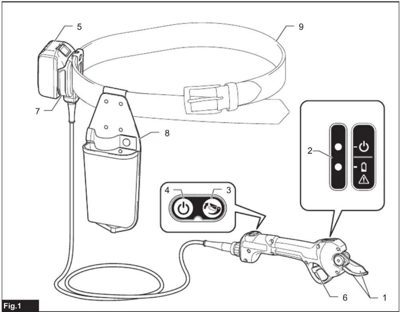
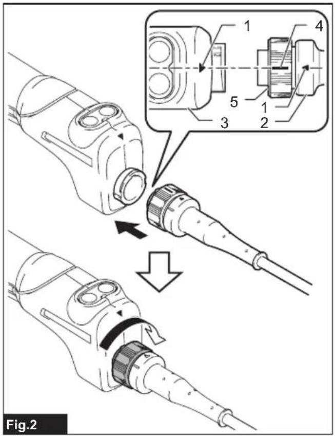
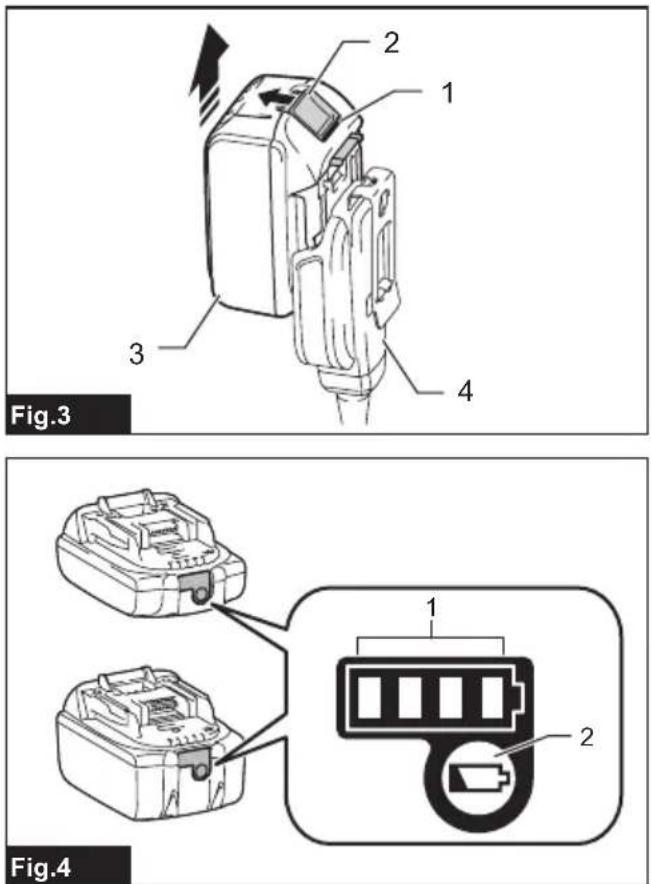
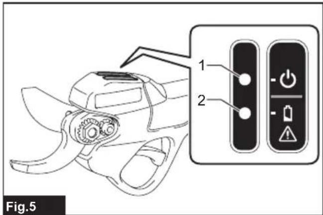
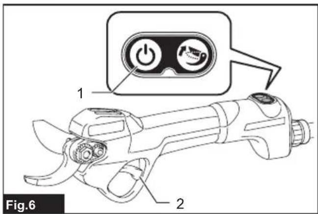
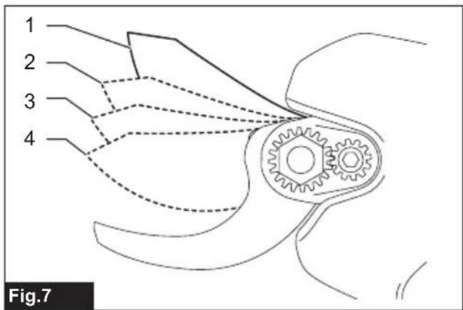
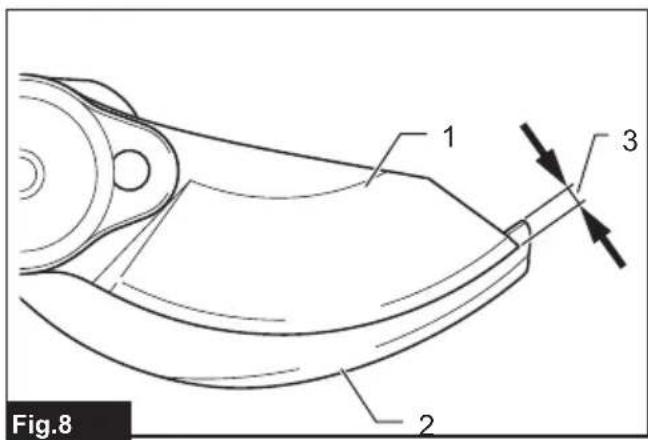
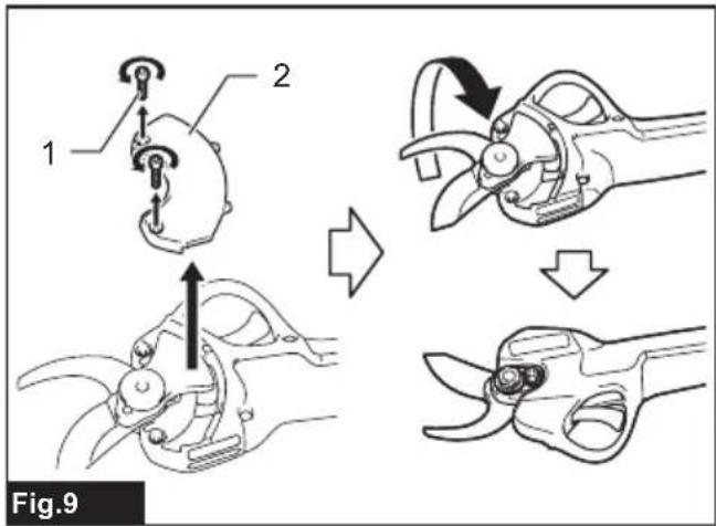
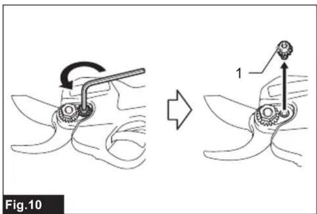
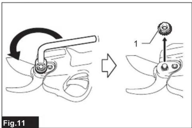
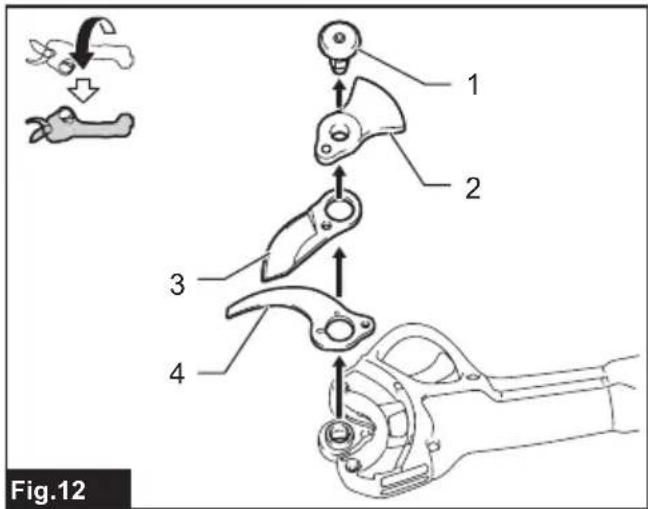
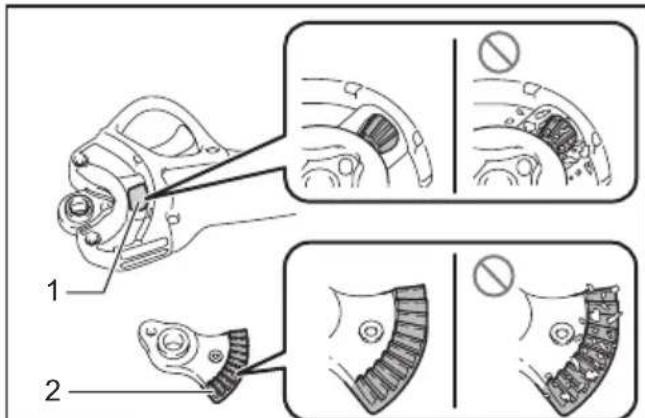
Fig.13

Fig.17
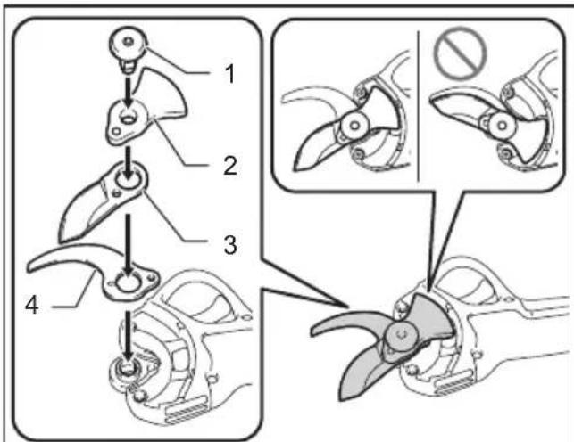
Fig.14
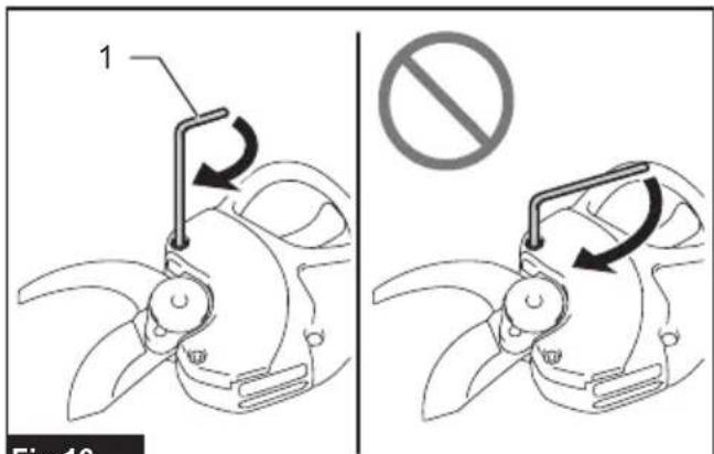
Fig.18
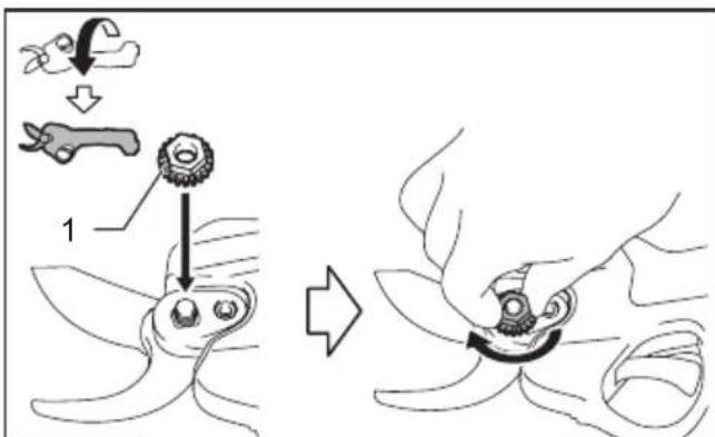
Fig.15
natural_image
Technical diagram showing two cross-sectional views of a mechanical component with a no-smoking symbol (no text or labels present)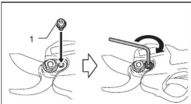
Fig.16
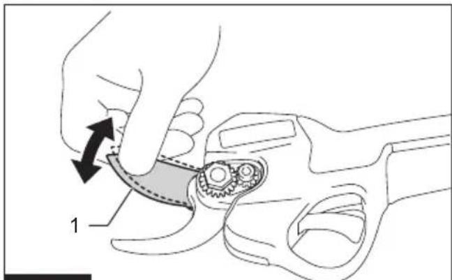
Fig.20
natural_image
Mechanical component diagram showing a lever mechanism with motion arrows (no text or symbols)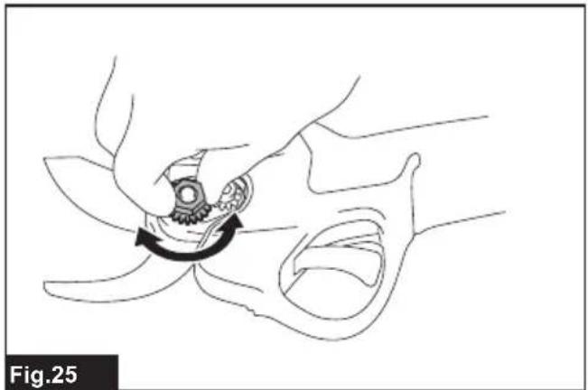
natural_image
Line drawing of a mechanical device interacting with a flower-like shape, showing motion direction (no text or symbols)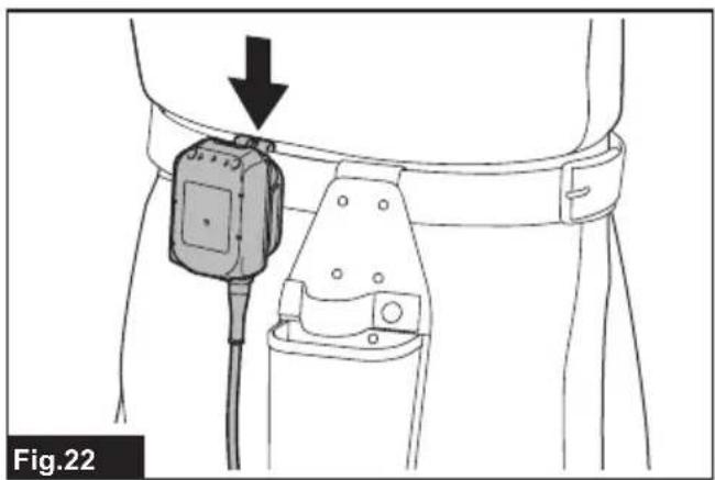
natural_image
Line drawing of a medical device with a black arrow pointing to a component, labeled Fig.22 (no text or symbols on the device itself)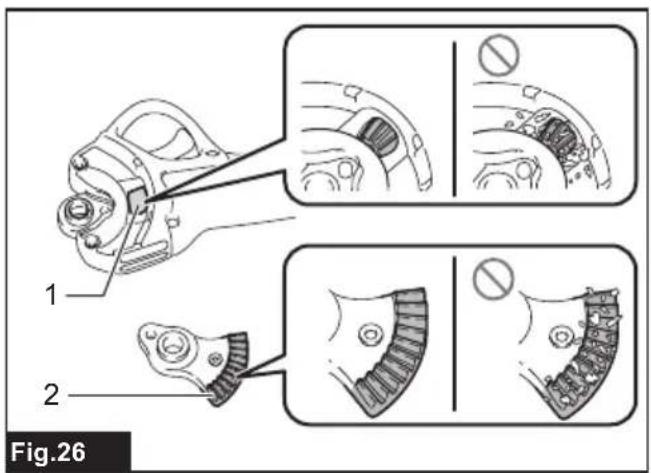
natural_image
Line drawing of a hand using a tool to adjust or install a mechanical component (no text or symbols present)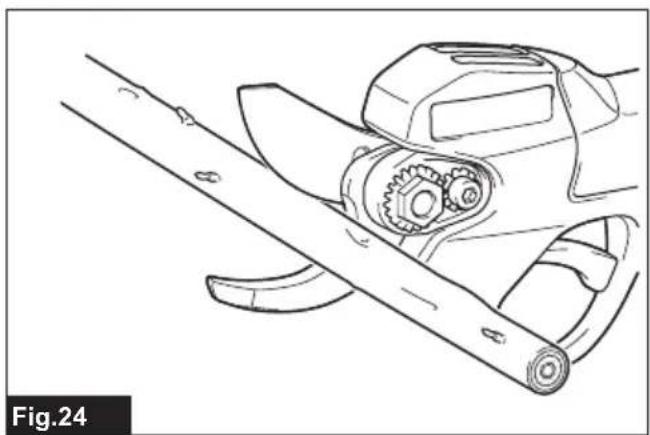
natural_image
Technical line drawing of a mechanical assembly with gears and rods (no text or symbols)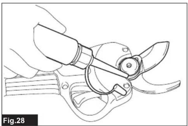
natural_image
Line drawing of a hand using a plow or sawtooth tool to cut a manual blade (no text or symbols)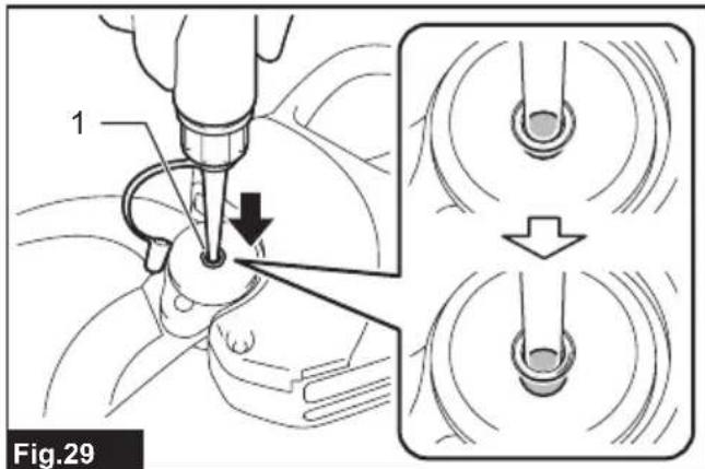
natural_image
Line drawing of a hand using a tool to cut a mechanical component, labeled Fig.30 (no text or symbols on the diagram itself)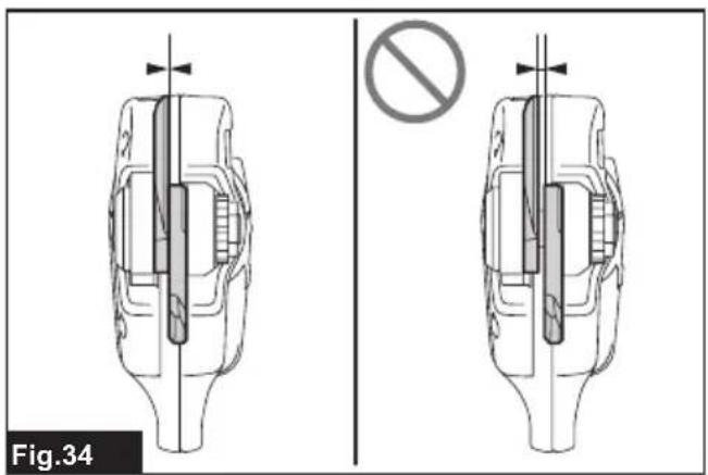
natural_image
Illustration of a hand holding a tool with an arrow indicating rotation (no text or symbols present)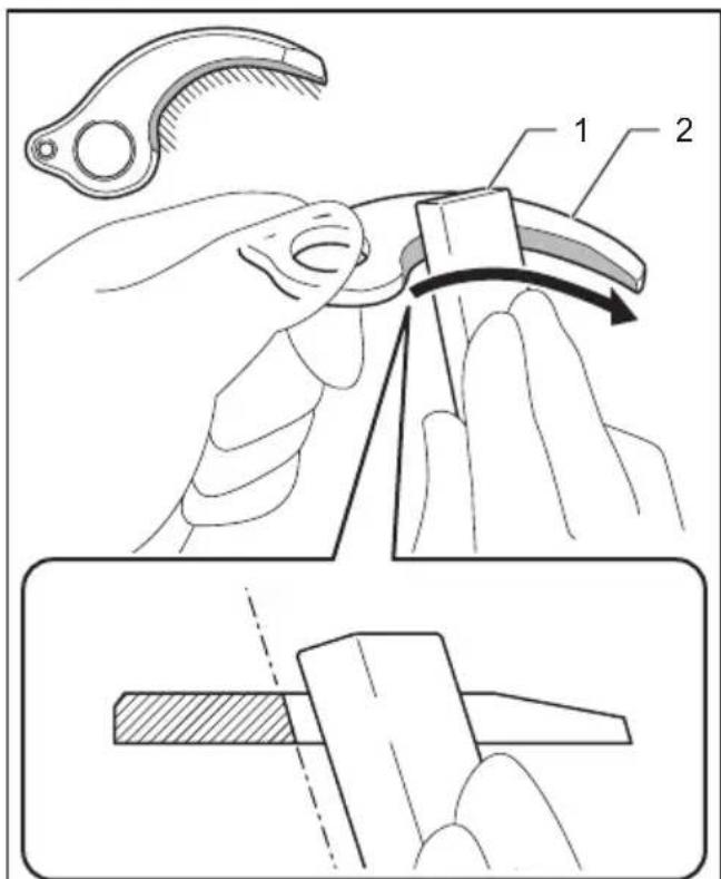
Fig.38
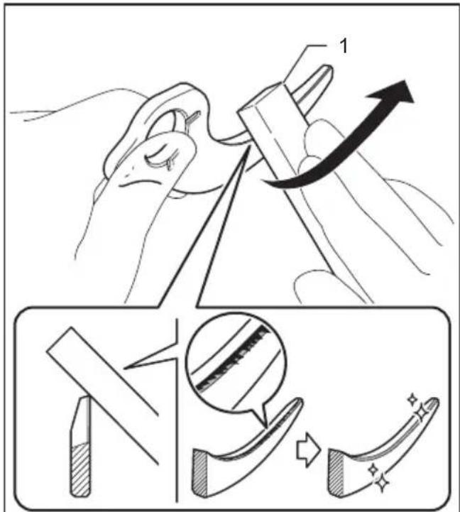
Fig.39
SPECIFICATIONS
| Model: DUP180 | |
| Max. cutting capacity ø30 mm | |
| Overall length(Shears part only) | 296 mm |
| Rated voltage D.C. 18 V | |
| Net weight * ^1 (Shears part only) | 0.68 kg |
- Due to our continuing program of research and development, the specifications herein are subject to change without notice.
• Specifications may differ from country to country.
*1 The weight according to EPTA-Procedure 01/2014 is shown in the table.
Applicable battery cartridge and charger
Battery cartridge BL1815N / BL1820B / BL1830B / BL1840B / BL1850B / BL1860B
Charger DC18RC / DC18RD / DC18RE / DC18SD / DC18SE / DC18SF /
DC18SH / DC18WC
- Some of the battery cartridges and chargers listed above may not be available depending on your region of residence.
WARNING: Only use the battery cartridges and chargers listed above. Use of any other battery cartridges and chargers may cause injury and/or fire.
⚠ WARNING: Do not use an optional corded power supply such as battery adapter or portable power pack with this tool. Do not connect two or more battery adapters for extension purpose.
Power cords or cables can be accidentally cut by the shear blades resulting in electric shock, fire and/or serious injury.
Symbols
The followings show the symbols which may be used for the equipment. Be sure that you understand their meaning before use.

Take particular care and attention.


Read instruction manual.

Danger; be aware of thrown objects.

Keep bystanders away.

DANGER - Keep hands away from blade.
Do not expose to moisture.

Ni-MH Li-ion
Only for EU countries
Due to the presence of hazardous components in the equipment, waste electrical and electronic equipment, accumulators and batteries may have a negative impact on the environment and human health. Do not dispose of electrical and electronic appliances or batteries with household waste!
In accordance with the European Directive on waste electrical and electronic equipment and on accumulators and batteries and waste accumulators and batteries, as well as their adaptation to national law, waste electrical equipment, batteries and accumulators should be stored separately and delivered to a separate collection point for municipal waste, operating in accordance with the regulations on environmental protection.
This is indicated by the symbol of the crossed-out wheeled bin placed on the equipment.
Intended use
The tool is intended for pruning twigs or branches.
Noise
The typical A-weighted noise level determined according to EN62841-4-5:
Sound pressure level ( L_pA ): 70 dB(A) or less
Uncertainty (K) : 3 dB (A)
The noise level under working may exceed 80 dB (A).
NOTE: The declared noise emission value(s) has been measured in accordance with a standard test method and may be used for comparing one tool with another.
NOTE: The declared noise emission value(s) may also be used in a preliminary assessment of exposure.
⚠ WARNING: Wear ear protection.
⚠ WARNING: The noise emission during actual use of the power tool can differ from the declared value(s) depending on the ways in which the tool is used especially what kind of workpiece is processed.
⚠ WARNING: Be sure to identify safety measures to protect the operator that are based on an estimation of exposure in the actual conditions of use (taking account of all parts of the operating cycle such as the times when the tool is switched off and when it is running idle in addition to the trigger time).
Vibration
The vibration total value (tri-axial vector sum) determined according to EN62841-4-5:
Vibration emission ( a_h ): 2.5 m/s ^2 or less
Uncertainty (K) : 1.5 m/s ^4
NOTE: The declared vibration total value(s) has been measured in accordance with a standard test method and may be used for comparing one tool with another.
NOTE: The declared vibration total value(s) may also be used in a preliminary assessment of exposure.
WARNING: The vibration emission during actual use of the power tool can differ from the declared value(s) depending on the ways in which the tool is used especially what kind of workpiece is processed.
⚠ WARNING: Be sure to identify safety measures to protect the operator that are based on an estimation of exposure in the actual conditions of use (taking account of all parts of the operating cycle such as the times when the tool is switched off and when it is running idle in addition to the trigger time).
Declarations of Conformity
For European countries only
The Declarations of conformity are included in Annex A to this instruction manual.
SAFETY WARNINGS
General power tool safety warnings
⚠ WARNING Read all safety warnings, instructions, illustrations and specifications provided with this power tool. Failure to follow all instructions listed
below may result in electric shock, fire and/or serious injury.
Save all warnings and instructions for future reference.
The term "power tool" in the warnings refers to your mains-operated (corded) power tool or battery-operated (cordless) power tool.
Pruning shears safety warnings
- Do not use the pruning shears in bad weather conditions, especially when there is a risk of lightning. This decreases the risk of being struck by lightning.
- Keep all power cords and cables away from cutting area. Power cords or cables may be hidden and can be accidentally cut by the blade.
- Hold the pruning shears by insulated gripping surfaces only, because the blade may contact hidden wiring or its own cord. Blades contacting a "live" wire may make exposed metal parts of the pruning shear "live" and could give the operator an electric shock.
- Keep all parts of the body away from the blade. Do not remove cut material or hold material to be cut when blades are moving.
- When clearing jammed material or servicing the pruning shears, make sure the power switch is off and the battery cartridge is removed. Unexpected actuation of the pruning shears while clearing jammed material or servicing may result in serious personal injury.
- Carry the pruning shears by the handle with the blade stopped and taking care not to operate the power switch. Proper carrying of the pruning shears will decrease the risk of inadvertent starting and resultant personal injury from the blades.
Additional Safety Instructions
- Use personal protective equipment. Always wear eye protection. Protective equipment such as a dust mask, non-skid safety shoes, hard hat or hearing protection used for appropriate conditions will reduce personal injuries.
- This tool is for pruning branches. Do not use it for any job except that for which it is intended.
- Never allow children, persons with reduced physical, sensory or mental capabilities or lack of experience and knowledge or people unfamiliar with these instructions to use the tool. Local regulations may restrict the age of the operator.
- Children should be supervised to ensure that they do not play with the appliance.
- Never operate the tool while people, especially children, or pets are nearby.
- Do not overreach and keep balance at all times. Always be sure of footing on slopes and to walk, never run.
-
Do not touch moving hazardous parts before the tool is disconnected from the mains and/or the battery cartridge is removed from the tool.
-
Always wear substantial footwear and long trousers while operating the tool.
- Disconnect the supply and/or remove the battery cartridge from the tool:
• whenever the tool is left by the user,
• before clearing a blockage,
• before checking, cleaning or working on the tool,
• after striking a foreign object to inspect the tool for damage,
- if the tool starts to vibrate abnormally, for immediately check.
- Never operate the tool with defective guards or shields, or without safety devices, or if the cord is damaged or worn.
- Avoid using the tool in bad weather conditions especially when there is a risk of lightning.
- Check the branches for foreign objects, such as wire fences or hidden wiring before operating the tool.
- Hold the tool firmly when using the tool.
- The tool is intended to be used by the operator at ground level. Do not use the tool on ladders or any other unstable support.
- Be careful not to catch foreign matter between the shear blades. If the shear blades are jammed with foreign matter, immediately switch off the tool and disconnect the battery from the tool. Then remove the foreign matter from the shear blades.
- Never hold the branch you are pruning with your free hand. Keep your free hand away from the cutting area. Never touch the shear blades, they are very sharp and you may cut yourself.
- Don't force the tool to make it cut. You could slip and injure yourself or cut something else unintentionally.
- Avoid cutting electrical wires that may be hidden.
- Handle the shear blades with extreme care to prevent cuts or injury from the shear blades.
- When not in use, always keep the tool in its holster.
- When power cords and cables get hot, stop using the tool and turn it off. Allow the tool to cool before a restart.
- Do not handle power plugs, sockets and connectors with wet hands. It may cause electric shock.
Important safety instructions for battery cartridge
- Before using battery cartridge, read all instructions and cautionary markings on (1) battery charger, (2) battery, and (3) product using battery.
- Do not disassemble or tamper with the battery cartridge. It may result in a fire, excessive heat, or explosion.
-
If operating time has become excessively shorter, stop operating immediately. It may result in a risk of overheating, possible burns and even an explosion.
-
If electrolyte gets into your eyes, rinse them out with clear water and seek medical attention right away. It may result in loss of your eyesight.
- Do not short the battery cartridge:
(1) Do not touch the terminals with any conductive material.
(2) Avoid storing battery cartridge in a container with other metal objects such as nails, coins, etc.
(3) Do not expose battery cartridge to water or rain.
A battery short can cause a large current flow, overheating, possible burns and even a breakdown.
- Do not store and use the tool and battery cartridge in locations where the temperature may reach or exceed 50 °C (122 °F).
- Do not incinerate the battery cartridge even if it is severely damaged or is completely worn out. The battery cartridge can explode in a fire.
-
Do not nail, cut, crush, throw, drop the battery cartridge, or hit against a hard object to the battery cartridge. Such conduct may result in a fire, excessive heat, or explosion.
-
Do not use a damaged battery.
-
The contained lithium-ion batteries are subject to the Dangerous Goods Legislation requirements.
For commercial transports e.g. by third parties, forwarding agents, special requirement on packaging and labeling must be observed.
For preparation of the item being shipped, consulting an expert for hazardous material is required. Please also observe possibly more detailed national regulations.
Tape or mask off open contacts and pack up the battery in such a manner that it cannot move around in the packaging.
- When disposing the battery cartridge, remove it from the tool and dispose of it in a safe place. Follow your local regulations relating to disposal of battery.
- Use the batteries only with the products specified by Makita. Installing the batteries to non-compliant products may result in a fire, excessive heat, explosion, or leak of electrolyte.
- If the tool is not used for a long period of time, the battery must be removed from the tool.
- During and after use, the battery cartridge may take on heat which can cause burns or low temperature burns. Pay attention to the handling of hot battery cartridges.
- Do not touch the terminal of the tool immediately after use as it may get hot enough to cause burns.
- Do not allow chips, dust, or soil stuck into the terminals, holes, and grooves of the battery cartridge. It may cause heating, catching fire, burst and malfunction of the tool or battery cartridge, resulting in burns or personal injury.
- Unless the tool supports the use near high-voltage electrical power lines, do not use the battery cartridge near high-voltage
electrical power lines. It may result in a malfunction or breakdown of the tool or battery cartridge.
18. Keep the battery away from children.
SAVE THESE INSTRUCTIONS.
CAUTION: Only use genuine Makita batteries. Use of non-genuine Makita batteries, or batteries that have been altered, may result in the battery bursting causing fires, personal injury and damage. It will also void the Makita warranty for the Makita tool and charger.
Tips for maintaining maximum battery life
- Charge the battery cartridge before completely discharged. Always stop tool operation and charge the battery cartridge when you notice less tool power.
- Never recharge a fully charged battery cartridge. Overcharging shortens the battery service life.
- Charge the battery cartridge with room temperature at 10 °C - 40 °C ( 50 °F - 104 °F ). Let a hot battery cartridge cool down before charging it.
- When not using the battery cartridge, remove it from the tool or the charger.
- Charge the battery cartridge if you do not use it for a long period (more than six months).
▶ Fig.1
1 Shear blade
2 Indicator lamps
3 Angle adjustment button
4 Main power button
5 Battery cartridge
6 Switch trigger
7 Battery adapter
8 Holster
9 Waist belt (available in the market)
CAUTION: Always be sure that the tool is switched off and the battery cartridge is removed before adjusting or checking function on the tool.
First, align the triangular mark of the female socket of the connection cord with the triangular mark of the male connector of the tool. Push in the socket of the connection cord to the connector of the tool. Then, align the marking on the coupling with the triangular marks, and push in and turn the coupling to tighten.
▶ Fig.2: 1. Triangular mark 2. Connection cord 3. Tool 4. Marking on coupling 5. Coupling
NOTICE: Turn the coupling and align the marking on the coupling with the triangular marks first when disconnecting the connection cord.
CAUTION: Always switch off the tool before installing or removing of the battery cartridge.
CAUTION: Hold the battery adapter and the battery cartridge firmly when installing or removing battery cartridge. Failure to hold the battery adapter and the battery cartridge firmly may cause them to slip off your hands and result in damage to the tool, battery adapter and battery cartridge and a personal injury.
To install the battery cartridge, align the tongue on the battery cartridge with the groove in the housing and slip it into place. Insert it all the way until it locks in place with a little click. If you can see the red indicator as shown in the figure, it is not locked completely.
To remove the battery cartridge, slide it from the battery adapter while sliding the button on the front of the cartridge.
CAUTION: Always install the battery cartridge fully until the red indicator cannot be seen. If not, it may accidentally fall out of the tool, causing injury to you or someone around you.
CAUTION: Do not install the battery cartridge forcibly. If the cartridge does not slide in easily, it is not being inserted correctly.
▶ Fig.3: 1. Red indicator 2. Button 3. Battery cartridge 4. Battery adapter
Indicating the remaining battery capacity
Only for battery cartridges with the indicator
Press the check button on the battery cartridge to indicate the remaining battery capacity. The indicator lamps light up for a few seconds.
▶ Fig.4: 1. Indicator lamps 2. Check button
| Indicator lamps Remaining | capacity | ||
| Lighted Off | Blinking | ||
 | 75% to 100% | ||
 | 50% to 75% | ||
 | 25% to 50% | ||
 | 0% to 25% | ||
 | Charge the battery. | ||
 •• •• | The battery may have malfunctioned. | ||
NOTE: Depending on the conditions of use and the ambient temperature, the indication may differ slightly from the actual capacity.
NOTE: The first (far left) indicator lamp will blink when the battery protection system works.
Tool / battery protection system
The tool is equipped with a tool/battery protection system. This system automatically cuts off power to the motor to extend tool and battery life. The tool will automatically stop during operation if the tool or battery is placed under one of the following conditions:
Overloaded:
The tool/battery is operated in a manner that causes it to draw an abnormally high current. In this situation, turn the tool off and stop the application that caused the tool to become overloaded. Then turn the tool on to restart.
If the tool does not start, the tool/battery is overheated. In this situation, let the tool/battery cool before turning the tool on again.
Low battery voltage:
When the remaining battery capacity becomes low, the tool does not operate. If you turn the tool on, the motor runs again but stops soon. In this situation, remove and recharge the battery.
Protections against other causes
Protection system is also designed for other causes that could damage the tool and allows the tool to stop automatically. Take all the following steps to clear the causes, when the tool has been brought to a temporary
halt or stop in operation.
- Turn the tool off, and then turn it on again to restart.
-
Charge the battery(ies) or replace it/them with recharged battery(ies).
-
Let the machine and battery(ies) cool down.
If no improvement can be found by restoring protection system, then contact your local Makita Service Center.
NOTICE: If the tool stops due to a cause not described above, refer to the section for troubleshooting.
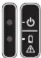
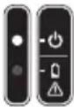
Indicator lamps
▶ Fig.5: 1. Indicator lamp (green) 2. Indicator lamp (red)
The meaning of indicator lamps is as follows:
| Indicator lamps Description | |||
| ●On Off | ○Blinking | ||
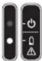 | The tool is turned on and ready to operate. | ||
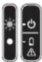 | The tool is turned on and in the standby mode. To return to the normal mode, pull the switch trigger twice. | ||
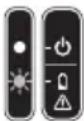 (Green indicator status may vary according to operating conditions.) (Green indicator status may vary according to operating conditions.) | The remaining battery capacity is low. | ||
 | The tool or battery is overheated, or the tool is overloaded, or the battery runs out. | ||
 | An abnormality has occurred. Turn the tool off, and then turn it on again. If the abnormality persists, ask your local authorized service center for repair. | ||
indicator status may ording to operating conditions.)
Main power button
⚠ WARNING: Always turn off the tool when not in use.
To turn on the tool, press and hold the main power button. The tool starts up in the standby mode and the green indicator lamp blinks in green.
To turn off the tool, pull and hold the switch trigger more than 3 seconds to close the shear blades, then release the switch trigger, and then press the main power button.
▶ Fig.6: 1. Main power button 2. Switch trigger
NOTE: This tool shifts to the standby mode when the switch trigger is not pulled for a certain period after the tool is turned on. When the green indicator lamp is blinking, pull the switch trigger twice to return to the normal mode.
NOTE: This tool employs the auto power-off function. To avoid unintentional start up. The tool automatically shuts down when the switch trigger is not pulled for a certain period after the tool is turned on.
Switch action
⚠️CAUTION: Before installing the battery cartridge into the tool, always check to see that the switch trigger actuates properly and returns to the "OFF" position when released.
Turn on the tool, and pull the switch trigger twice to open the upper shear blade. The green indicator lamp lights up in green. When you pull the switch trigger, the upper shear blade closes, and when you release the switch trigger, the upper shear blade opens.
Switching the shear blade angle
The opening angle of the shear blades can be set in four levels. You can switch the opening angle according to the branches to be cut.
▶ Fig.7: 1. ∅30 mm 2. ∅25 mm 3. ∅18 mm 4. ∅10 mm
To switch the opening angle, follow the steps below.
-
Turn on the tool and pull the switch trigger twice to open the shear blades.
-
While pulling the switch trigger fully, press and hold the angle adjustment button until the green indicator lamp blinks twice. Then release the switch trigger.
The green indicator lamp starts blinking fast.
-
Pull the switch trigger repeatedly so that the opening angle switches to your desired position.
-
Press and hold the angle adjustment button to complete the adjustment.
The green indicator lamp stops blinking and lights up.
Cutting depth adjustment
After grinding or replacing the shear blades, adjust the cutting depth. To adjust the cutting depth, follow the steps below.
-
Turn on the tool and pull the switch trigger twice to open the shear blades.
-
While pulling the switch trigger fully, press and hold the angle adjustment button for a few seconds until the green indicator lamp blinks fast.
-
Adjust the cutting depth by pulling the switch trigger repeatedly so that the overlap of the tips of the upper and lower shear blades is 1 to 3 mm.
▶ Fig.8: 1. Upper shear blade 2. Lower shear blade 3. 1 - 3 mm
NOTE: The upper shear blade returns to the shallowest position when you pull the switch trigger after the upper shear blade reaches the deepest position.
NOTE: If the tool is overloaded while adjusting the cutting depth adjustment, the green lamp blinks and red lamp lights up. In this case, turn off the tool, then remove the cause of the overload, and then adjust the cutting depth again.
- Press and hold the angle adjustment button to complete the adjustment. The green indicator lamp stops blinking and lights up.
ASSEMBLY
CAUTION: Always be sure that the tool is switched off and the battery cartridge is removed before carrying out any work on the tool.
CAUTION: When replacing the shear blades, always wear gloves so that your hands do not directly contact the shear blades.
Removing or installing the shear blades
- Loosen the bolts with the hex wrench, then slide the cover slightly and remove the bolts and cover, and then turn over the tool.
▶ Fig.9: 1. Bolt 2. Cover
- Loosen the bolt with the hex wrench, and then remove it.
▶ Fig.10: 1. Bolt
NOTICE: Do not loosen the nut before loosening the bolt. Otherwise, the nut may be damaged.
- Loosen the nut with the box wrench, and then remove it.
▶ Fig.11: 1. Nut
- Turn over the tool, and then remove the bolt, blade holder, upper shear blade, and lower shear blade in order.
▶ Fig.12: 1. Bolt 2. Blade holder 3. Upper shear blade 4. Lower shear blade
NOTICE: If there are pieces of debris such as wood chips on the blade holder or around the gear, clean up them.
Remaining debris will affect cutting performance, resulting in malfunctions.
▶ Fig.13: 1. Gear 2. Blade holder
NOTE: After cleaning, apply grease to the gear.
- Attach the lower shear blade, upper shear blade, blade holder, and bolt to the tool in order.
▶ Fig.14: 1. Bolt 2. Blade holder 3. Upper shear blade 4. Lower shear blade
NOTICE: When attaching the upper shear blade, make sure that the upper shear blade is placed in the direction shown in the figure.
- Turn over the tool, and then attach the nut to the tool and tighten it manually.
▶ Fig.15: 1. Nut
NOTICE: The recommended tightening torque is approximately 0.5 N·m.
- Attach the bolt to the tool and tighten it with the hex wrench.
▶ Fig.16: 1. Bolt
- Turn over the tool, then attach the cover to the tool, and then tighten the bolts with the hex wrench.
▶ Fig.17: 1. Bolt 2. Cover
NOTICE: Tighten the bolts with the hex wrench in the upright position as shown in the figure. Tightening the bolts too much may damage the bolts.
▶ Fig.18: 1. Hex wrench
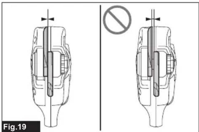
After installing the shear blades, check the clearance of shear blades by confirming the following points. If the clearance is not proper, adjust it by referring to the section for adjustment for shear blades clearance.
- Check that there is no gap between the upper shear blade and lower shear blade.
▶ Fig.19
- Check that the upper shear blade moves approximately 3 mm toward the lower shear blade.
▶ Fig.20: 1. Upper shear blade
After installing the shear blades, apply oil to the shear blades by referring to the section for shear blade maintenance.
After installing the shear blades, adjust the cutting depth by referring to the section for cutting depth adjustment.
OPERATION
⚠️CAUTION: Always hold the tool firmly. And keep firm footing.
⚠️CAUTION: Do not put any of your body parts near the shear blades during operation.
⚠CAUTION: Before use, inspect if the shear blades, bolts or other parts are not worn or damaged. Replace worn or damaged parts for safe operation.
NOTICE: If the shear blades are stuck in a branch during operation, do not twist the tool. Release the switch trigger and turn off the tool, and then pull the shear blades straight out slowly from the branch. Otherwise the shear blades may be damaged.
NOTICE: In case you cut too thick branch or something too hard, the overload protection works and the tool stops. In this case, release the switch trigger and turn off the tool, and then pull the shear blades straight out slowly from the branch.
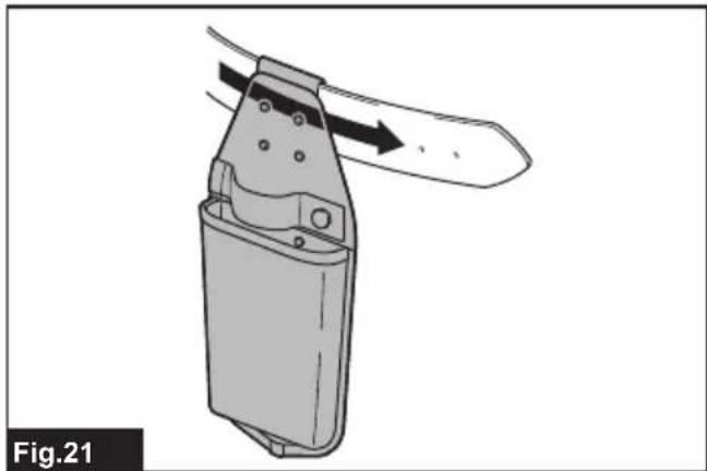
Setting up holster and battery adapter
Pass the waist belt through the opening of the holster as shown in the figure, and then tighten the waist belt.
▶ Fig.21
Hang the battery adapter on the waist belt.
▶ Fig.22
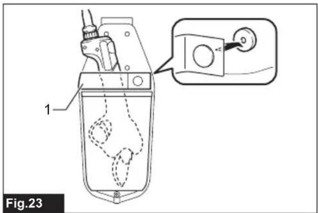
Insert the tool into the holster. You can fix the tool with the strap. Before inserting the tool into the holster, close the upper shear blade by pulling the switch trigger for more than 3 seconds, and turn off the tool.
▶ Fig.23: 1. Strap
Pruning operation
Maintain your proper footing and balance at all times and cut branches one by one. The maximum thickness of branches which can be cut with the tool is approximately 30 mm.
▶ Fig.24
MAINTENANCE
CAUTION: Always be sure that the tool is switched off and the battery cartridge is removed before attempting to perform inspection or maintenance.
CAUTION: Wear safety gloves when handling the shear blade. Otherwise it may result in personal injury.
NOTICE: Never use gasoline, benzine, thinner, alcohol or the like. Discoloration, deformation or cracks may result.
To maintain product SAFETY and RELIABILITY, repairs, any other maintenance or adjustment should be performed by Makita Authorized or Factory Service Centers, always using Makita replacement parts.
Checking the nut tightness
NOTICE: Check the tightness of the nut before each use to prevent premature gear wear.
Turn the nut left and right with your fingers. If the nut turns easily, it is loose. Retighten the nut by referring to
the section for adjusting shear blades tension.
▶ Fig.25
Cleaning the gear box
NOTICE: Clean the gear and gear box after each use.
Remaining debris will affect cutting performance, resulting in malfunctions.
- Referring to the section for removing or installing the shear blades, remove the cover and the shear blades.
- Clean up debris such as wood chips accumulated on the blade holder, gear and gear box.
▶ Fig.26: 1. Gear 2. Blade holder
NOTE: After cleaning, apply grease to the gear.
- Referring to the section for removing or installing the shear blades, install the shear blades and the cover.
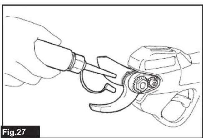
Shear blade maintenance
NOTICE: Failure to perform blade maintenance may cause excessive blade friction and shorten the operating time per battery charge.
Before the operation or once per hour during operation, apply low-viscosity oil (machine oil, or spray-type lubricating oil) to the shear blades.
▶ Fig.27
▶ Fig.28
Apply oil through the lubrication hole by pressing the hole with the tip of the oil bottle.
▶ Fig.29: 1. Lubrication hole
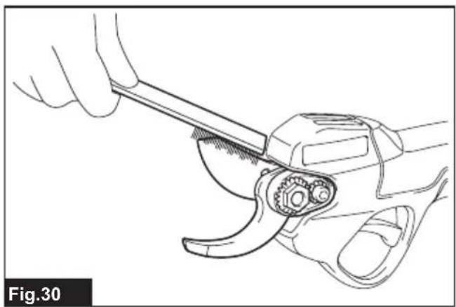
After the operation, remove dust from the shear blades with a wire brush. Wipe the shear blades off with a cloth. Then apply low-viscosity oil (machine oil, or spray-type lubricating oil) to the shear blades.
▶ Fig.30
Adjusting shear blades tension
NOTICE: Adjust the tension on your shear blades properly. Too loose tension may result in dull cut, and too tight tension may result in overload for the motor and short running time of the tool.
Adjust the tension on shear blades as follows:
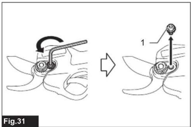
- Loosen the bolt with the hex wrench, and then remove it.
▶ Fig.31: 1. Bolt
NOTICE: Do not loosen the nut before loosening the bolt. Otherwise, the nut may be damaged.
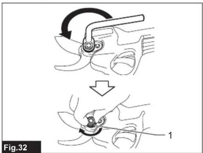
- Loosen the nut with the box wrench, and then tighten it manually.
▶ Fig.32: 1. Nut
NOTICE: The recommended tightening torque is approximately 0.5 N·m.
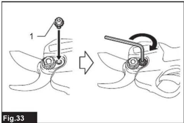
- Attach the bolt to the tool and tighten it with the hex wrench.
▶ Fig.33: 1. Bolt - Check that there is no gap between the upper shear blade and lower shear blade.
▶ Fig.34
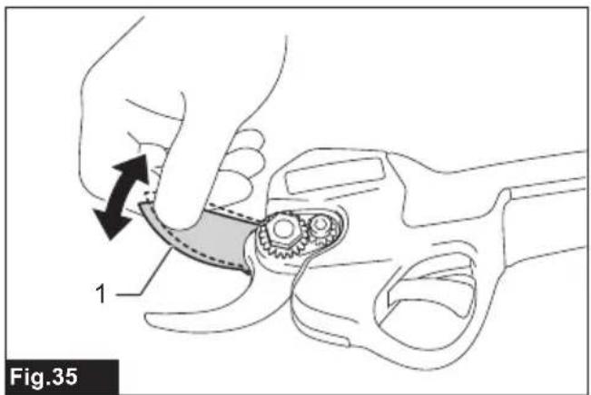
Check that the upper shear blade moves approximately 3 mm toward the lower shear blade.
▶ Fig.35: 1. Upper shear blade
Grinding the shear blades
NOTE: When grinding the shear blades, adding water to the grinding stone will make the grinding smoother. After the grinding, be sure to wipe off the shear blades with a dry cloth.
Turn off the tool and remove the battery cartridge, and remove the shear blades from the tool.
Upper shear blade
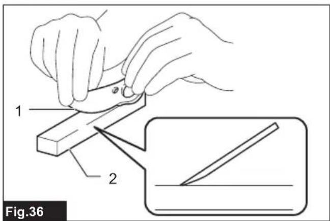
- Grind the upper shear blade with the grinding stone as shown in the figure.
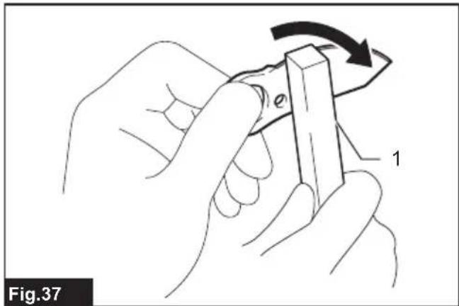
▶ Fig.36: 1. Upper shear blade 2. Grinding stone - Remove the burrs from the back side of the shear blade by lightly applying the grinding stone to the shear blade.
▶ Fig.37: 1. Grinding stone
Lower shear blade
-
Grind the lower shear blade with the grinding stone in the direction of the arrow as shown in the figure.
▶ Fig.38: 1. Grinding stone 2. Lower shear blade -
Remove the burrs from the back side of the shear blade by lightly applying the grinding stone to the shear blade.
▶ Fig.39: 1. Grinding stone
NOTICE: When sharpening the back side of shear blade, lightly apply the grinding stone, and do not sharpen the shear blade too much.
Otherwise, the clearance between the upper blade and lower blade edges may become too much, or the life of shear blade may be shortened.
• After installing the shear blades, adjust the tension on shear blades by referring to the section for adjusting shear blades tension.
• After installing the shear blades, apply oil to the shear blades by referring to the section for shear blade maintenance.
- After installing the shear blades, adjust the cutting depth by referring to the section for cutting depth adjustment.
TROUBLESHOOTING
Before asking for repairs, conduct your own inspection first. If you find a problem that is not explained in the manual, do not attempt to dismantle the tool. Instead, ask Makita Authorized Service Centers, always using Makita replacement parts for repairs.
| State of abnormality Probable cause | (malfunction) Remedy | |
| The shear blade does not move even after pulling the switch trigger. | The battery is low. Charge the battery. | |
| The tool is turned off. Turn on the tool. | ||
| The switch trigger is defective. Stop using the tool immediately, and ask your local authorized service center for repair. | ||
| The shear blades are stuck on the branch. | The branch is too thick or too hard. Release the switch trigger and turn off the tool. Then pull the shear blades straight out slowly from the branch. | |
| The cut is not smooth. | The shear blades are dull. | Sharpen the shear blades, and adjust the blade clearance, and perform cutting depth adjustment. |
| The shear blades are worn out. Replace the shear blades. | ||
OPTIONAL ACCESSORIES
⚠️CAUTION: These accessories or attachments are recommended for use with your Makita tool specified in this manual. The use of any other accessories or attachments might present a risk of injury to persons. Only use accessory or attachment for its stated purpose.
If you need any assistance for more details regarding these accessories, ask your local Makita Service Center.
• Upper shear blade
- Lower shear blade
- Grinding stone
• Makita genuine battery and charger
NOTE: Some items in the list may be included in the tool package as standard accessories. They may differ from country to country.
SPÉCIFICATIONS
▶ Fig.29: 1. Orifice de lubrification
▶ Abb.18: 1. Inbusschlüssel
⚠ WAARSCHUWING: Draag gehoorbescherming.
VEILIGHEIDSWAAR- SCHUWINGEN
▶ Fig.29: 1. Smeeropening
OPTIONELE ACCESSOIRES
▶ Fig.18: 1. Llave hexagonal
▶ Fig.18: 1. Chave hexagonal
