
UN001G - Hedge trimmers MAKITA - Free user manual and instructions
Find the device manual for free UN001G MAKITA in PDF.

| Product type | Cordless pole hedge trimmer |
| Brand | Makita |
| Model | UN001G |
| Blade length | 600 mm |
| Number of strokes per minute | 2000 / 3000 / 4000 min⁻¹ (3 adjustable speeds) |
| Cutting angle | 115° (45° upward, 70° downward) |
| Total length | 2268 mm |
| Rated voltage | 36 V - 40 V DC max |
| Net weight (without battery) | 4.0 kg |
| Weight with battery (according to EPTA 01/2014) | 4.7 to 5.9 kg |
| Protection degree | IPX4 (splash resistant) |
| Compatible batteries | BL4020, BL4025, BL4040, BL4040F, BL4050F, BL4080F |
| Compatible chargers | DC40RA, DC40RB, DC40RC, DC40WA |
| Sound pressure level | 82 dB(A) (uncertainty K = 3 dB(A)) |
| Measured sound power level | 93 dB(A) (guaranteed 94 dB(A)) |
| Vibration (left hand / right hand) | 4.9 m/s² / 3.5 m/s² (uncertainty K = 1.5 m/s²) |
| Electronic functions | Constant speed control, electric brake, accidental restart prevention |
| Adjustable speed | Yes, 3 levels (low 2000, medium 3000, high 4000 min⁻¹) |
| Reverse for debris | Yes, reverse button |
| Adjustable head angle | 6 positions: 45° up to 70° down |
| Protection system | Against overload, overheating, excessive discharge |
| Standard equipment | Shoulder strap, blade cover |
| Blade maintenance | Lubricate with oil before use and after cleaning, sharpenable |
| Warranty | See Makita conditions |
Frequently Asked Questions - UN001G MAKITA
User questions about UN001G MAKITA
0 question about this device. Answer the ones you know or ask your own.
Ask a new question about this device
Download the instructions for your Hedge trimmers in PDF format for free! Find your manual UN001G - MAKITA and take your electronic device back in hand. On this page are published all the documents necessary for the use of your device. UN001G by MAKITA.
USER MANUAL UN001G MAKITA
natural_image
Line drawing of a manual tool with long-handled handle and lever (no text or symbols)


natural_image
Diagram of a mechanical component with two curved arrows indicating motion, labeled 'Fig.16' (no text or symbols on the diagram itself)
natural_image
Line drawing of a person wearing a hard hat and safety harness, holding a belt (no text or symbols)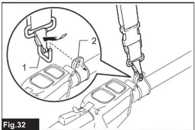
natural_image
Line drawing of a person using a mechanical tool, no text or symbols present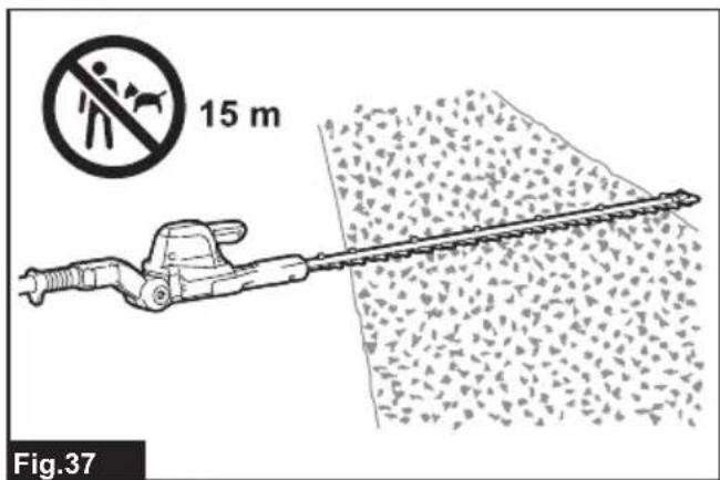
natural_image
Diagram of a mechanical tool cutting through granular material, with an arrow indicating direction (no text or symbols)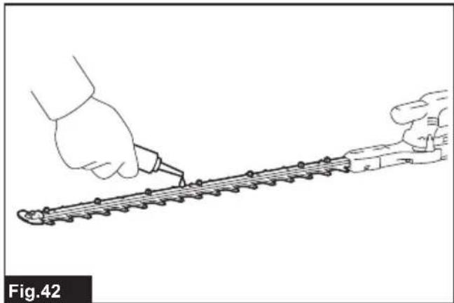
natural_image
Line drawing of a hand using a tool to trim a metal strip, labeled Fig.42 (no text or symbols on the diagram itself)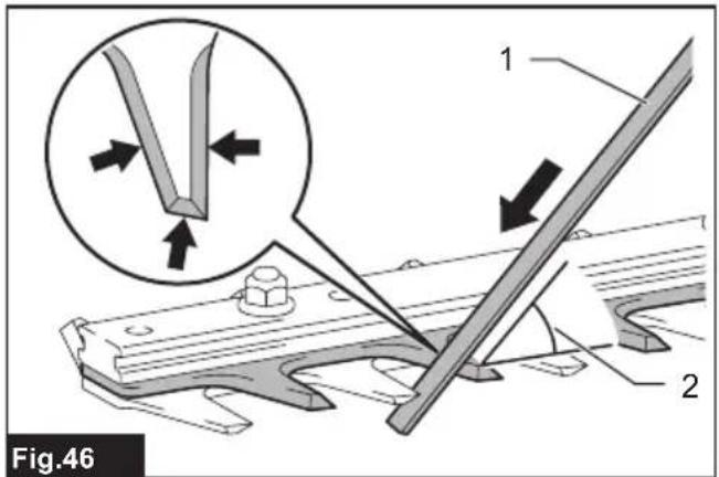
natural_image
Illustration of a hand using a tool to cut a chain or chain with a tool, labeled Fig.43 (no text or symbols on the diagram itself)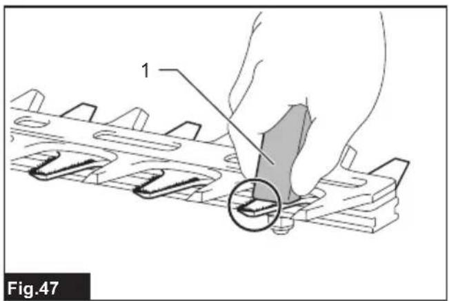
natural_image
Technical illustration of two blade hedges with a diagonal line and a prohibition symbol (no text or labels)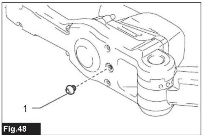
natural_image
Technical line drawing of a mechanical assembly with labeled component '1' and dashed alignment line (no text or symbols beyond label)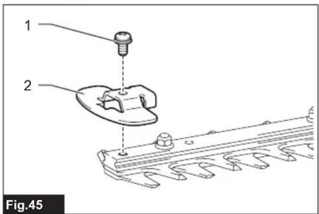
SPECIFICATIONS
| Model: UN001G | ||
| Blade length 600 mm | ||
| Strokes per minute 2,000 / 3,000 / 4,000 min | -1 | |
| Cutting blade angle 115° (up 45°, down 70°) | ||
| Overall length 2,268 mm | ||
| Rated voltage D.C. 36 V - 40 V max | ||
| Net weight *1 4.0 kg | ||
| *2 4.7 - 5.9 kg | ||
| Protection degree IPX4 | ||
- Due to our continuing program of research and development, the specifications herein are subject to change without notice.
• Specifications may differ from country to country.
*1: Weight without any accessories or battery cartridge(s)
*2: The weight may differ depending on the attachment(s), including the battery cartridge. The lightest and heaviest combinations, according to EPTA-Procedure 01/2014, are shown in the table.
Applicable battery cartridge and charger
| Battery cartridge BL4020 / BL4025 / BL4040 / BL4040F / BL4050F / BL4080F |
| Charger DC40RA / DC40RB / DC40RC / DC40WA |
- Some of the battery cartridges and chargers listed above may not be available depending on your region of residence.

WARNING: Only use the battery cartridges and chargers listed above. Use of any other battery cartridges and chargers may cause injury and/or fire.
Recommended cord connected power source
| Portable power pack | PDC01 / PDC1200 / PDC1500 |
• The cord connected power source(s) listed above may not be available depending on your region of residence.
• Before using the cord connected power source, read instruction and cautionary markings on them.
Symbols
The followings show the symbols which may be used for the equipment. Be sure that you understand their meaning before use.


Ni-MH Li-ion
Only for EU countries
Due to the presence of hazardous components in the equipment, waste electrical and electronic equipment, accumulators and batteries may have a negative impact on the environment and human health. Do not dispose of electrical and electronic appliances or batteries with household waste!
In accordance with the European Directive on waste electrical and electronic equipment and on accumulators and batteries and waste accumulators and batteries, as well as their adaptation to national law, waste electrical equipment, batteries and accumulators should be stored separately and delivered to a separate collection point for municipal waste, operating in accordance with the regulations on environmental protection.
This is indicated by the symbol of the crossed-out wheeled bin placed on the equipment.

Guaranteed sound power level according to EU Outdoor Noise Directive.
Noise
The typical A-weighted noise level determined according to EN62841-4-2:
| Model Sound pressure level | Guaranteed sound power level | Measured sound power level | |||
| L_pA (dB(A)) | Uncertainty K (dB(A)) | L_wA (dB(A)) | L_wA (dB(A)) | Uncertainty K (dB(A)) | |
| UN001G 82 3 94 93 1.5 | |||||
NOTE: The declared noise emission value(s) has been measured in accordance with a standard test method and may be used for comparing one tool with another.
NOTE: The declared noise emission value(s) may also be used in a preliminary assessment of exposure.
WARNING: Wear ear protection.
WARNING: The noise emission during actual use of the power tool can differ from the declared value(s) depending on the ways in which the tool is used especially what kind of workpiece is processed.
WARNING: Be sure to identify safety measures to protect the operator that are based on an estimation of exposure in the actual conditions of use (taking account of all parts of the operating cycle such as the times when the tool is switched off and when it is running idle in addition to the trigger time).
Vibration
The vibration total value (tri-axial vector sum) determined according to EN62841-4-2:
| Model Left hand (Front grip / Handle) | Right hand (Rear grip) | |||
| ah (m/s2) Uncertainty K(m/s2) | ah (m/s2) Uncertainty K(m/s2) | |||
| UN001G 4.9 1.5 3.5 1.5 | ||||
NOTE: The declared vibration total value(s) has been measured in accordance with a standard test method and may be used for comparing one tool with another.
NOTE: The declared vibration total value(s) may also be used in a preliminary assessment of exposure.
WARNING: The vibration emission during actual use of the power tool can differ from the declared value(s) depending on the ways in which the tool is used especially what kind of workpiece is processed.
WARNING: Be sure to identify safety measures to protect the operator that are based on an estimation of exposure in the actual conditions of use (taking account of all parts of the operating cycle such as the times when the tool is switched off and when it is running idle in addition to the trigger time).
Declarations of Conformity
For European countries only
The Declarations of conformity are included in Annex A to this instruction manual.
SAFETY WARNINGS
General power tool safety warnings
WARNING Read all safety warnings, instructions, illustrations and specifications provided with this power tool. Failure to follow all instructions listed below may result in electric shock, fire and/or serious injury.
Save all warnings and instructions for future reference.
The term "power tool" in the warnings refers to your mains-operated (corded) power tool or battery-operated (cordless) power tool.
Cordless pole hedge trimmer safety warnings
Cordless hedge trimmer safety warnings:
- Do not use the hedge trimmer in bad weather conditions, especially when there is a risk of lightning. This decreases the risk of being struck by lightning.
- Keep all power cords and cables away from cutting area. Power cords or cables may be
hidden in hedges or bushes and can be accidentally cut by the blade.
- Wear ear protection. Adequate protective equipment will reduce the risk of hearing loss.
- Hold the hedge trimmer by insulated gripping surfaces only, because the blade may contact hidden wiring. Blades contacting a "live" wire may make exposed metal parts of the hedge trimmer "live" and could give the operator an electric shock.
- Keep all parts of the body away from the blade. Do not remove cut material or hold material to be cut when blades are moving. Blades continue to move after the switch is turned off. A moment of inattention while operating the hedge trimmer may result in serious personal injury.
- When clearing jammed material or servicing the hedge trimmer, make sure all power switches are off and the battery pack is removed or disconnected. Unexpected actuation of the hedge trimmer while clearing jammed material or servicing may result in serious personal injury.
- Carry the hedge trimmer by the handle with the blade stopped and taking care not to operate any power switch. Proper carrying of the hedge trimmer will decrease the risk of inadvertent starting and resultant personal injury from the blades.
- When transporting or storing the hedge trim-mer, always use the blade cover. Proper handling of the hedge trimmer will decrease the risk of personal injury from the blades.
Cordless pole hedge trimmer safety warnings:
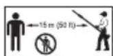
- Always use head protection when operating the pole hedge trimmer overhead. Falling debris can result in serious personal injury.
- Always use two hands when operating the pole hedge trimmer. Hold the pole hedge trimmer with both hands to avoid loss of control.
- To reduce the risk of electrocution, never use the pole hedge trimmer near any electrical power lines. Contact with or use near power lines may cause serious injury or electric shock resulting in death.
Additional Safety Warnings
Preparation
- THIS HEDGE TRIMMER CAN CAUSE SERIOUS INJURIES. Read the instructions carefully for the correct handling, preparation, maintenance, starting and stopping of the tool. Become familiar with all controls and the proper use of the tool.
- Check the hedges and bushes for foreign objects, such as wire fences or hidden wiring before operating the tool.
- The tool must not be used by children or young persons under 18 years of age. Young persons over 16 years of age may be exempted from this restriction if they are undergoing training under the supervision of an expert.
-
In the event of an emergency, switch off the tool and remove the battery cartridge immediately.
-
DANGER - Keep hands away from blade. Contact with blade will result in serious personal injury.
- Only use with handle and guard properly assembled to the tool. The use of the tool without the proper guard or handle provided may result in serious personal injury.
- First-time users should have an experienced user show them how to use the tool.
- Before operation, examine the work area for wire fences, stones, or other solid objects. They can damage the blades.
- Use the tool only if you are in good physical condition. If you are tired, your attention will be reduced. Be especially careful at the end of a working day. Perform all work calmly and carefully. The user is responsible for all damages to third parties.
- Before starting work, check to make sure that the tool is in good and safe working order. Ensure guards are fitted properly. The tool must not be used unless fully assembled.
- Avoid dangerous environment. Do not use the tool in damp or wet locations or expose it to rain. Water entering the tool will increase the risk of electric shock.
Personal protective equipment
- Work gloves of stout leather are part of the basic equipment of the tool and must always be worn when working with it. Also wear sturdy shoes with anti-skid soles.
- Wear ear protection such as ear muffs to prevent hearing loss.
- Wear protective goggles, safety helmet and protective gloves to protect yourself from flying debris or falling objects.
- When touching blades or adjusting the blade angle, wear protective gloves. Blades can cut bare hands severely.
Operation
- Always use two hands to operate the tool fitted with two handles. Using one hand could cause loss of control and result in serious personal injury.
- While operating the tool, always ensure that the operating position is safe and secure. Overreaching with the tool, particularly from a ladder, is extremely dangerous. Do not work from anything wobbly or infirm.
- Do not simultaneously wear multiple belt harnesses and/or shoulder harnesses when operating the tool.
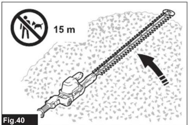
- During operation, keep bystanders or animals at least 15 m away from the tool. Stop the tool as soon as someone approaches.
-
If cutting tool strikes any object or the tool starts making unusual noise or vibration, switch off the tool and remove the battery cartridge immediately and allow the tool to stop. And then take the following steps:
-
inspect for damage
-
check for, and tighten, any loose parts
• have any damaged parts replaced or repaired with genuine spare parts. -
Only use the tool for its intended purpose. Do not use the tool for any other purpose.
-
Switch off the tool and remove the battery cartridge before:
-
cleaning or when clearing a blockage,
- checking, carrying out maintenance or working on the tool,
-
adjusting the working position of the shear blades,
• leaving the tool unattended. -
Ensure that the tool is correctly located in a designated working position before starting the tool.
- Do not operate the tool with a damaged or excessively worn shear blades.
- Always ensure that all handles and guards are fitted when using the tool. Never attempt to use an incomplete tool or one fitted with an unauthorized modification.
- Always be aware of your surroundings and stay alert for possible hazards of which you may not be aware due to the noise of the tool.
- Be careful not to accidentally contact a metal fence or other hard objects during operation. The blade will break and may cause serious injury.
- Avoid unintentional starting. Do not carry the tool when the battery cartridge is installed and with finger on the switch. Make sure that the switch is off when installing the battery cartridge.
- Do not grasp the exposed cutting blades or cutting edges when picking up or holding the tool.
- Do not force the tool. It will do the job better and with less likelihood of a risk of injury at the rate for which it was designed.
- Do not use the tool in the rain or in wet or very damp conditions. The electric motor is not waterproof.
- Hold the tool firmly when using the tool.
- Do not operate the tool at no-load unnecessarily.
- Before checking the shear blades, taking care of faults, or removing foreign objects caught in the shear blades, always switch off the tool and remove the battery cartridge.
- Never point the shear blades to yourself or others.
- If the blades stop moving due to the stuck of foreign objects between the blades during operation, switch off the tool and remove the battery cartridge, and then remove the foreign objects using tools such as pliers. Removing the foreign objects by hand may cause an injury for the reason that the blades may move in reaction to removing the foreign objects.
- Make sure there are no electrical cables, water pipes, gas pipes etc. that could cause a hazard if damaged by use of the tool.
-
Do not touch the metal parts or hot surfaces of the tool during use or immediately after operation; they may be extremely hot and could burn your skin. Let the tool cool down before carrying out any work on the tool.
-
Do not use the tool on soft/unstable/slippery ground or steep inclines. Avoid working on ladders or at heights. Doing otherwise may cause a risk of falling, resulting in personal injury.
- Do not use the tool in bad weather or at night where visibility is limited. Failure to do so may cause fall or incorrect operation due to low visibility.
- Avoid working in poor environment where increased user fatigue is expected.
- Do not submerge the tool into a puddle.
- Do not leave the tool unattended outdoors in the rain.
- When wet leaves or dirt adhere to the suction mouth (ventilation window) due to rain, remove them.
- Do not use the tool in the snow.
Electrical and battery safety
- Do not dispose of the battery(ies) in a fire. The cell may explode. Check with local codes for possible special disposal instructions.
- Do not open or mutilate the battery(ies). Released electrolyte is corrosive and may cause damage to the eyes or skin. It may be toxic if swallowed.
- Do not charge battery in rain, or in wet locations.
- Do not charge the battery outdoors.
- Do not handle charger, including charger plug, and charger terminals with wet hands.
- Do not replace the battery with wet hands.
- Do not replace the battery in the rain.
- Do not wet the terminal of battery with liquid such as water, or submerge the battery. Do not leave the battery in the rain, nor charge, use, or store the battery in a damp or wet place. If the terminal gets wet or liquid enters inside of battery, the battery may be short circuited and there is a risk of overheat, fire, or explosion.
- After removing the battery from the tool or charger, be sure to attach the battery cover to the battery and store it in a dry place.
- If the battery cartridge gets wet, drain the water inside and then wipe it with a dry cloth. Dry the battery cartridge completely in a dry place before use.
Maintenance and storage
- When the tool is stopped for servicing, inspection or storage, switch off the tool and remove the battery cartridge, and make sure all moving parts have come to a stop. Allow the tool to cool before making any inspections, adjustment, etc.
- Always allow the tool to cool down before storing.
- When not in use, attach the blade cover to the tool and store the tool indoors in dry, and high locked-up place, out of reach of children.
-
Maintain the tool with care. Keep cutting edge sharp and clean for best performance and to reduce the risk of injury. Follow instructions for lubricating and changing accessories. Keep handles dry, clean, and free from oil and grease.
-
Check damaged parts. Before further use of the tool, any part which is damaged should be carefully checked to determine that it will operate properly and perform its intended function. Check for alignment of moving parts, binding of moving parts, breakage of parts, mounting and any other condition that may affect its operation. A guard or other part that is damaged should be properly repaired or replaced by your authorized service center.
- Use genuine spare parts only.
- When moving the tool to another location, including during work, always remove the battery cartridge and put the blade cover on the shear blades. Never carry or transport the tool with the blades running. Never grasp the blades with your hands.
- Clean the tool and especially the shear blades after use, and before putting the tool into storage for extended periods. Lightly oil the shear blades and put on the blade cover.
- Do not wash the tool with high pressure water.
- When washing the tool, do not let water enter the electrical mechanism such as battery, motor, and terminals.
- Perform inspection or maintenance in a place where rain can be avoided.
- After using the tool, remove the adhered dirt and dry the tool completely before storing. Depending on the season or the area, there is a risk of malfunction due to freezing.
- When storing the tool, avoid direct sunlight and rain, and store it in a place where it does not get hot or humid.
SAVE THESE INSTRUCTIONS.
⚠ WARNING: DO NOT let comfort or familiarity with product (gained from repeated use) replace strict adherence to safety rules for the subject product. MISUSE or failure to follow the safety rules stated in this instruction manual may cause serious personal injury.
Important safety instructions for battery cartridge
- Before using battery cartridge, read all instructions and cautionary markings on (1) battery charger, (2) battery, and (3) product using battery.
- Do not disassemble or tamper with the battery cartridge. It may result in a fire, excessive heat, or explosion.
- If operating time has become excessively shorter, stop operating immediately. It may result in a risk of overheating, possible burns and even an explosion.
-
If electrolyte gets into your eyes, rinse them out with clear water and seek medical attention right away. It may result in loss of your eyesight.
-
Do not short the battery cartridge:
(1) Do not touch the terminals with any conductive material.
(2) Avoid storing battery cartridge in a container with other metal objects such as nails, coins, etc.
(3) Do not expose battery cartridge to water or rain.
A battery short can cause a large current flow, overheating, possible burns and even a breakdown.
-
Do not store and use the tool and battery cartridge in locations where the temperature may reach or exceed 50 °C (122 °F).
-
Do not incinerate the battery cartridge even if it is severely damaged or is completely worn out. The battery cartridge can explode in a fire.
-
Do not nail, cut, crush, throw, drop the battery cartridge, or hit against a hard object to the battery cartridge. Such conduct may result in a fire, excessive heat, or explosion.
-
Do not use a damaged battery.
-
The contained lithium-ion batteries are subject to the Dangerous Goods Legislation requirements. For commercial transports e.g. by third parties, forwarding agents, special requirement on packaging and labeling must be observed. For preparation of the item being shipped, consulting an expert for hazardous material is required. Please also observe possibly more detailed national regulations. Tape or mask off open contacts and pack up the battery in such a manner that it cannot move around in the packaging.
-
When disposing the battery cartridge, remove it from the tool and dispose of it in a safe place. Follow your local regulations relating to disposal of battery.
- Use the batteries only with the products specified by Makita. Installing the batteries to non-compliant products may result in a fire, excessive heat, explosion, or leak of electrolyte.
- If the tool is not used for a long period of time, the battery must be removed from the tool.
- During and after use, the battery cartridge may take on heat which can cause burns or low temperature burns. Pay attention to the handling of hot battery cartridges.
- Do not touch the terminal of the tool immediately after use as it may get hot enough to cause burns.
- Do not allow chips, dust, or soil stuck into the terminals, holes, and grooves of the battery cartridge. It may cause heating, catching fire, burst and malfunction of the tool or battery cartridge, resulting in burns or personal injury.
- Unless the tool supports the use near high-voltage electrical power lines, do not use the battery cartridge near high-voltage electrical power lines. It may result in a malfunction or breakdown of the tool or battery cartridge.
- Keep the battery away from children.
SAVE THESE INSTRUCTIONS.
⚠️CAUTION: Only use genuine Makita batteries. Use of non-genuine Makita batteries, or batteries that have been altered, may result in the battery bursting causing fires, personal injury and damage. It will also void the Makita warranty for the Makita tool and charger.
Tips for maintaining maximum battery life
- Charge the battery cartridge before completely discharged. Always stop tool operation and
charge the battery cartridge when you notice less tool power.
- Never recharge a fully charged battery cartridge. Overcharging shortens the battery service life.
- Charge the battery cartridge with room temperature at 10 °C - 40 °C (50 °F - 104 °F). Let a hot battery cartridge cool down before charging it.
- When not using the battery cartridge, remove it from the tool or the charger.
- Charge the battery cartridge if you do not use it for a long period (more than six months).
PARTS DESCRIPTION
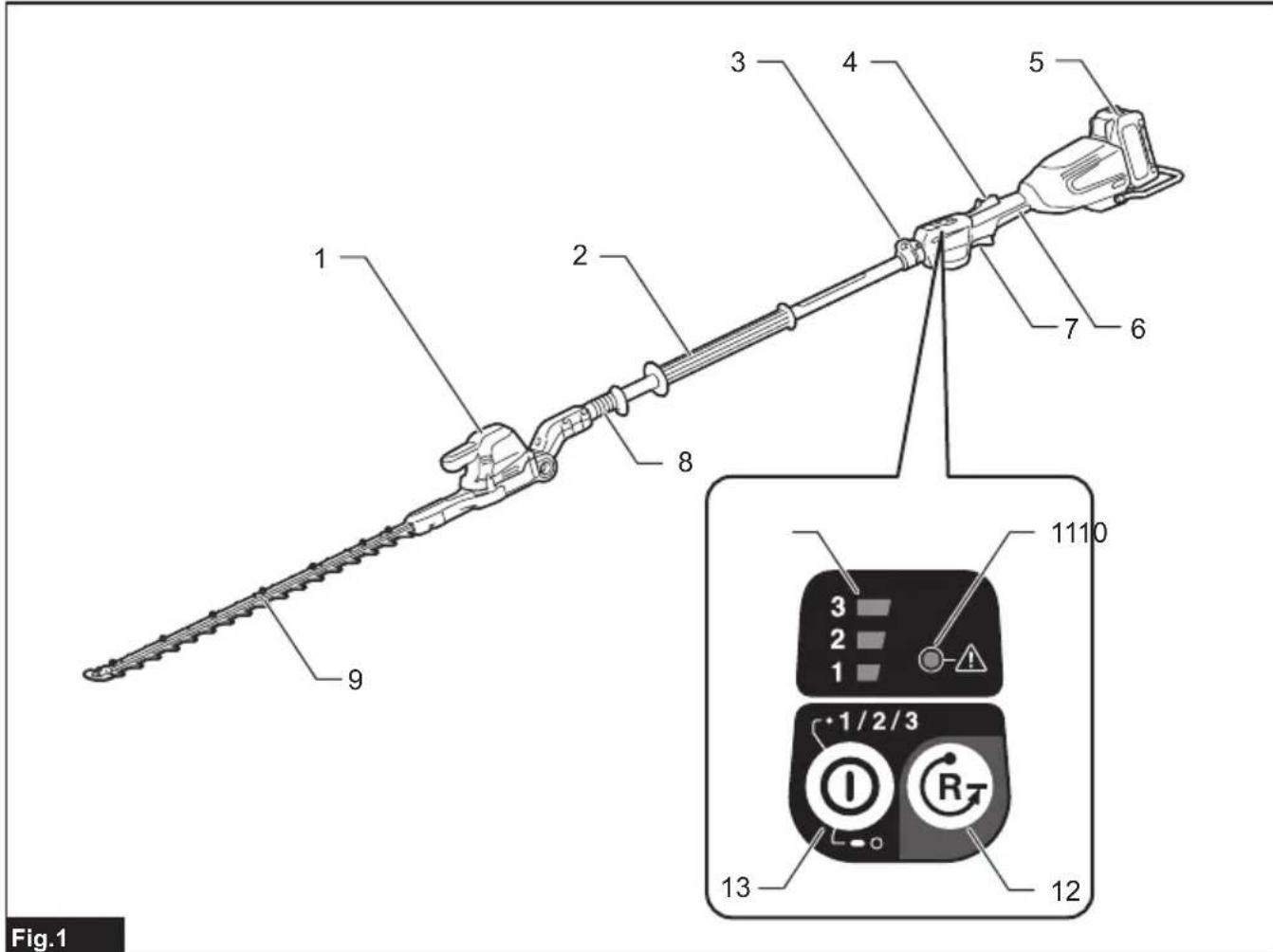
▶ Fig.1
| 1 | Head | 2 | Front grip | 3 | Hanger | 4 | Lock-off lever |
| 5 | Battery cartridge | 6 | Rear grip | 7 | Switch lever | 8 | Slide sleeve |
| 9 | Shear blades | 10 | Speed indicator | 11 | Caution lamp | 12 | Reverse button |
| 13 Main power button - - - - - |
FUNCTIONAL DESCRIPTION
⚠️CAUTION: Always be sure that the tool is switched off and the battery cartridge is removed before adjusting or checking function on the tool.
Installing or removing battery cartridge
⚠️CAUTION: Always switch off the tool before installing or removing of the battery cartridge.
⚠️CAUTION: Hold the tool and the battery cartridge firmly when installing or removing battery cartridge. Failure to hold the tool and the battery cartridge firmly may cause them to slip off your hands and result in damage to the tool and battery cartridge and a personal injury.
To install the battery cartridge, align the tongue on the battery cartridge with the groove in the housing and slip it into place. Insert it all the way until it locks in place with a little click. If you can see the red indicator as shown in the figure, it is not locked completely.
To remove the battery cartridge, slide it from the tool while sliding the button on the front of the cartridge.
▶ Fig.2: 1. Red indicator 2. Button 3. Battery cartridge
CAUTION: Always install the battery cartridge fully until the red indicator cannot be seen. If not, it may accidentally fall out of the tool, causing injury to you or someone around you.
⚠️ CAUTION: Do not install the battery cartridge forcibly. If the cartridge does not slide in easily, it is not being inserted correctly.
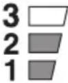
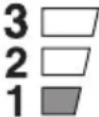
Indicating the remaining battery capacity
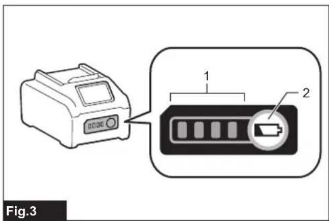
Press the check button on the battery cartridge to indicate the remaining battery capacity. The indicator lamps light up for a few seconds.
▶ Fig.3: 1. Indicator lamps 2. Check button
| Indicator lamps | Remaining capacity | ||
| Lighted | Off | Blinking | |
 | 75% to 100% | ||
 | 50% to 75% | ||
 | 25% to 50% | ||
 | 0% to 25% | ||
 | Charge the battery. | ||
 + +  | The battery may have malfunctioned. | ||
NOTE: Depending on the conditions of use and the ambient temperature, the indication may differ slightly from the actual capacity.
NOTE: The first (far left) indicator lamp will blink when the battery protection system works.
Tool / battery protection system
The tool is equipped with tool/battery protection system. This system automatically cuts off power to the motor to extend tool and battery life. The tool will automatically stop during operation if the tool or battery is placed under one of the following conditions:
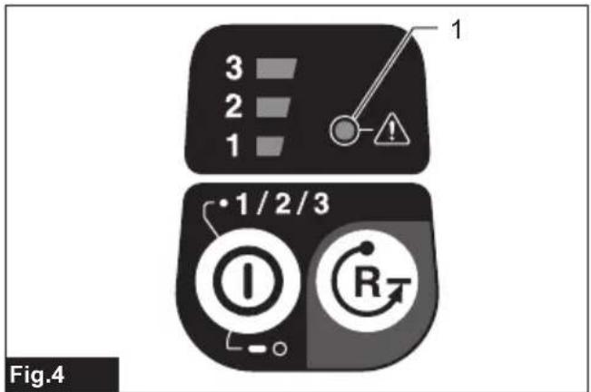
▶ Fig.4: 1. Caution lamp
| Caution lamp Status | ||
| Color |  | |
| Green | ### | Overload |
| Red | ### | Overheat |
| Red | ### | Over discharge |
NOTICE: Depending on the usage conditions, the tool automatically stops without any indication if the branches or debris are entangled in the tool. In this case, switch off the tool and remove the battery cartridge, and then remove entangled branches or debris using tools such as pliers. After removing the branches or debris, install the battery cartridge and turn on the tool again.
Overload protection
If the tool or battery is overloaded by entangled branches or other debris, the tool automatically stops and the caution lamp starts blinking in green. In this situation, turn the tool off and stop the application that caused the tool to become overloaded. Then turn the tool on to restart.
Overheat protection for tool or battery
If the tool or battery cartridge is overheated, the tool stops automatically. When the tool is overheated, the caution lamp lights up in red. When the battery cartridge is overheated, the caution lamp blinks in red. Let the tool and/or battery cool down before turning the tool on again.
Overdischarge protection
When the battery capacity becomes low, the tool stops automatically and the caution lamp starts blinking in red. If the tool does not operate even when the switches are operated, remove the battery cartridge from the tool and charge it.
Protections against other causes
Protection system is also designed for other causes that could damage the tool and allows the tool to stop automatically. Take all the following steps to clear the causes, when the tool has been brought to a temporary halt or stop in operation.
- Turn the tool off, and then turn it on again to restart.
- Charge the battery(ies) or replace it/them with recharged battery(ies).
- Let the machine and battery(ies) cool down.
If no improvement can be found by restoring protection system, then contact your local Makita Service Center.
Power switch action
WARNING: For your safety, this tool is equipped with lock-off switch which prevents the tool from unintended starting. NEVER use the tool if it runs when you simply pull the switch lever without pressing the lock-off lever. Return the tool to our authorized service center for proper repairs BEFORE further usage.
WARNING: NEVER tape down or defeat purpose and function of lock-off lever.
⚠️ CAUTION: Before installing the battery cartridge in the tool, always check to see that the switch lever actuates properly and returns to the "OFF" position when released. Operating a tool with a switch that does not actuate properly can lead to loss of control and serious personal injury.
CAUTION: Never put your finger on the switch when carrying. The tool may start unintentionally and cause injury.
NOTICE: Do not pull the switch lever hard without pressing the lock-off lever. This can cause switch breakage.
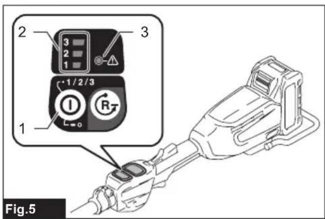
Press the main power button to turn on the tool. To turn off the tool, press and hold the main power button until the speed indicator goes off.
▶ Fig.5: 1. Main power button 2. Speed indicator 3. Caution lamp
NOTE: The caution lamp blinks in green if the switch lever is pulled under unoperatable conditions as follows:
- Turning on the main power switch while holding down the lock-off lever and the switch lever.
- Pulling the switch lever with the lock-off lever being held down while folding the tool head.
NOTE: This tool employs the auto power-off function. The main power switch will automatically shut down if the tool is not operated for approximately 5 minute(s).
NOTE: The auto power-off function can be served when the tool stops due to protection system operation. The main power switch will automatically shut down approximately 5 minute(s) after the motor automatically stops and no corrective action is taken against tool protection.
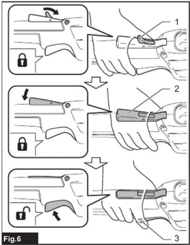
To prevent the switch lever from being accidentally pulled, a double lock-off switch is provided for safety. To start the tool, push the lock lever down forward past its normal position using the web of your hand (i.e., the part between thumb and index finger) and squeeze the lock-off lever with your palm. Then pull the switch lever with the lock-off lever being held.
Release the switch lever to stop.
▶ Fig.6: 1. Lock lever 2. Lock-off lever 3. Switch lever
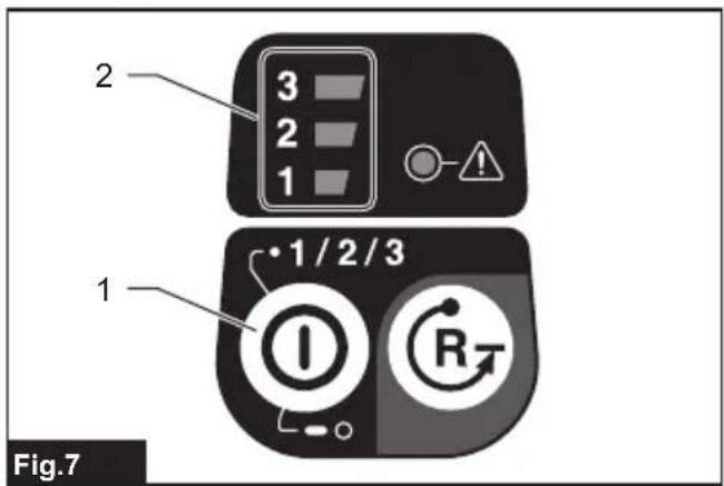
Speed adjusting
You can adjust the tool speed by pressing the main power button. Each time you press the main power button, the level of speed changes.
▶ Fig.7: 1. Main power button 2. Speed indicator
| Indicator Mode | Stroke speed | |
 | High 4,000 min | -1 |
 | Medium 3,000 min | -1 |
 | Low 2,000 min | -1 |
NOTE: The tool starts in the same mode as the last operation. If you remove the battery while the motor is running after the shutdown, the tool may not start in the same mode as the last operation.
Reverse button for debris removal
⚠ WARNING: If the entangled branches or debris cannot be removed by the reverse function, switch off the tool and remove the battery cartridge, and then remove the entangled branches or debris using tools such as pliers. Failure to switch off the tool and remove the battery cartridge may result in serious personal injury from accidental start-up. Removing the entangled branches or debris by hand may cause an injury, since the shear blades may move in reaction to removing them.
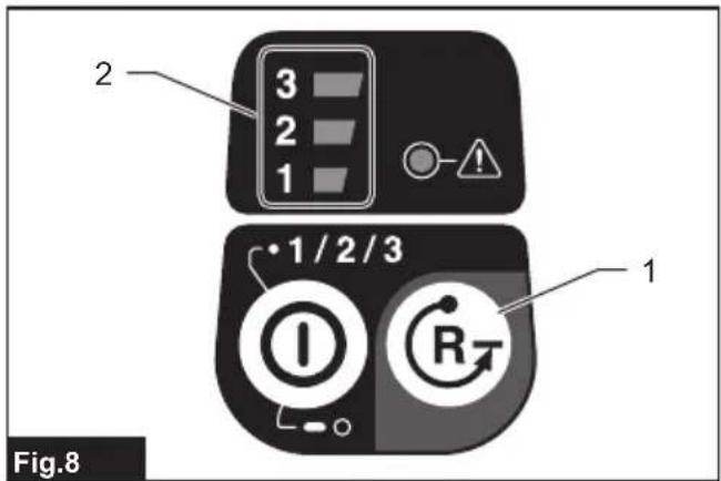
This tool has a reverse button to change the direction of shear blades movement. It is only for removing branches and debris entangled in the tool.
To reverse the shear blades movement, press the reverse button when the shear blades have stopped, and then pull the switch lever while pressing the lock-off lever. The speed indicator starts blinking, and the shear blades move in reverse direction.
When entangled branches and debris are removed, the tool returns to the regular movement and the speed indicator stops blinking and lights up.
▶ Fig.8: 1. Reverse button 2. Speed indicator
NOTE: If the entangled branches or debris cannot be removed, release the switch lever, then press the reverse button, and then pull the switch lever until they are removed.
NOTE: If you press the reverse button while the shear blades are still moving, the tool comes to stop and to be ready for reverse movement.
Adjusting the cutting angle
CAUTION: Always be sure that the tool is switched off before folding or unfolding the head.
CAUTION: When folding the head for carrying the tool or after using the tool, be sure to attach the blade cover before folding the head.
CAUTION: When folding the head, be careful not to pinch your fingers between the head and the slide sleeve.
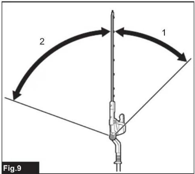
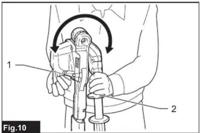
The angle of the head can be adjusted in 6 steps at between 45^ upward and 70^ downward. To change the angle of the head, follow the steps below.
▶ Fig.9: 1. Upward head angles 2. Downward head angles
- Hold the head and the slide sleeve as shown in the figure.
▶ Fig.10: 1. Head 2. Slide sleeve - Move the head while holding down the slide sleeve, and then release the slide sleeve.
- Move the head slightly until it is locked with a click.
NOTE: Make sure that the head is securely locked before operating the tool.
Electronic function
The tool is equipped with the electronic functions for easy operation.
- Constant speed control
The speed control function provides the constant rotation speed regardless of load conditions.
- Electric brake
This tool is equipped with an electric brake. If the tool consistently fails to stop the shear blades quickly after the switch lever is released, have the tool serviced at Makita Authorized Service Center.
• Accidental re-start preventive function
When you turn on the tool while pulling the switch lever, the tool does not start and the caution lamp blinks in green. To start the tool, first release the switch lever and then turn on the tool.
ASSEMBLY
CAUTION: Always be sure that the tool is switched off and the battery cartridge is removed before carrying out any work on the tool.
⚠️ CAUTION: When replacing the shear blades, always wear gloves so that your hands do not directly contact the blades.
Installing or removing the shear blades
⚠️ CAUTION: Attach the blade cover before removing or installing the shear blades.
NOTICE: When replacing the shear blades, do not wipe off grease from the gear and crank.
NOTE: Before installing or removing the shear blades, unfold the head of the tool so that the head is straight to the tool body.
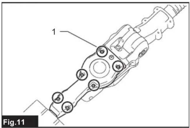
- Place the tool upside down, and then remove the 6 bolts.
▶ Fig.11: 1. Bolt - Remove the cover and the plate.
▶ Fig.12: 1. Cover 2. Plate
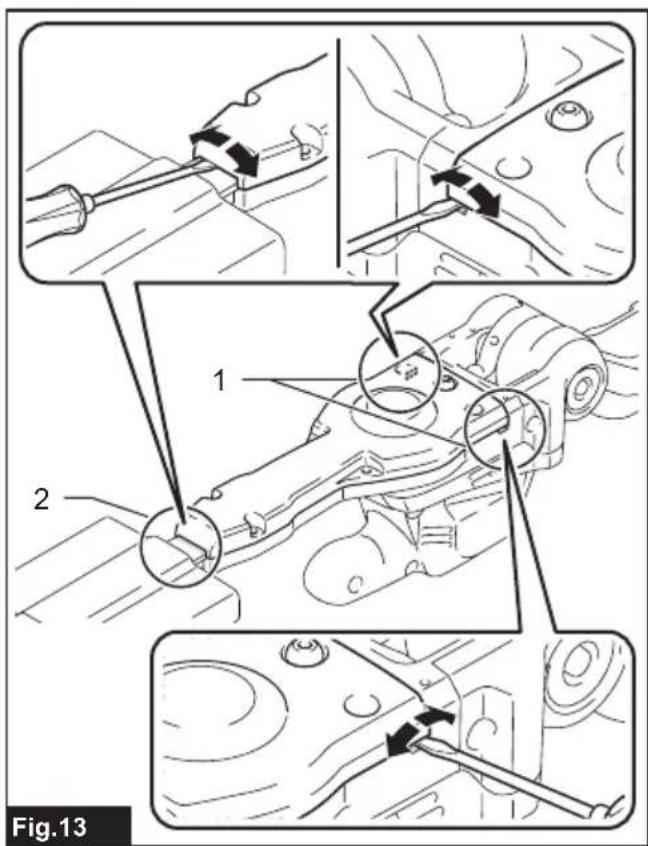
Use a slotted screwdriver to pry the cover open if you find it hard to open the cover.
Insert the slotted screwdriver into one or more of the opening and cutouts on the tool housing, and then lift the cover out of the housing.
▶ Fig.13: 1. Cutouts (on both sides of housing) 2. Opening (between cover and shear blades)
NOTE: The plate may remain inside the cover.
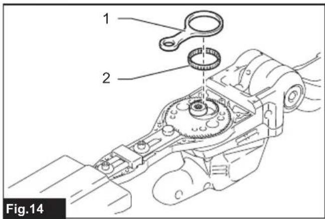
- Remove the connecting rod and the bearing.
▶ Fig.14: 1. Connecting rod 2. Bearing
NOTE: The connecting rod and the bearing may remain inside the cover.
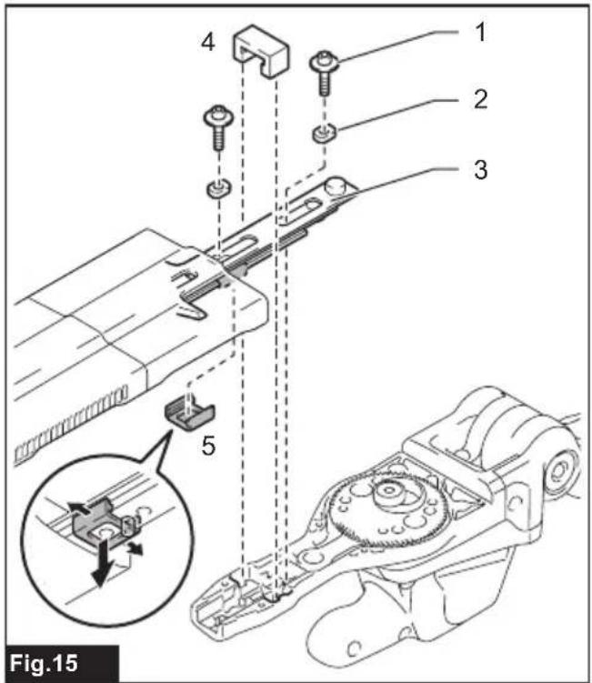
- Remove the 2 bolts and the 2 sleeves from the shear blades. Disassemble the shear blades from the tool body. Then detach the felt pad and the rubber dust seal from the shear blades.
▶ Fig.15: 1. Bolt 2. Sleeve 3. Shear blades 4. Felt pad 5. Dust seal
NOTICE: Be careful not to lose pieces of component parts as they will be reused for reassembly.
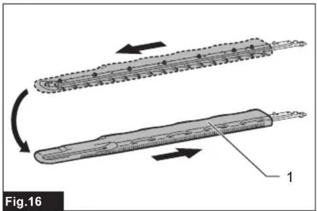
- Remove the blade cover, and then attach it to the new shear blades.
▶ Fig.16: 1. Blade cover - Adjust the crank so that 2 holes are lined up on the alignment line.
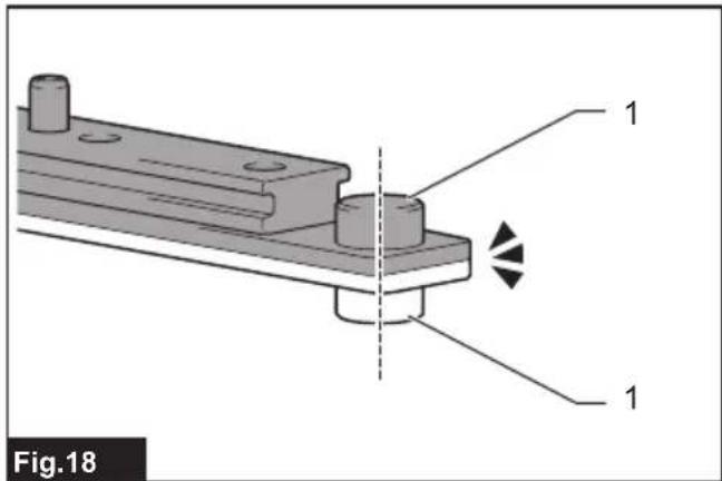
▶ Fig.17: 1. Holes 2. Alignment line - Align the protruding parts on both sides of the shear blades.
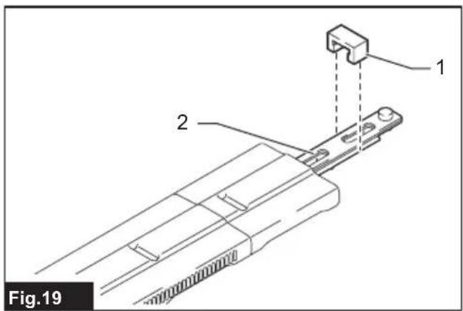
▶ Fig.18: 1. Protruding parts - Hold the shear blades with their sleeve holes facing upwards. Attach the felt pad to the shear blades as its arms wrap around the shear blades.
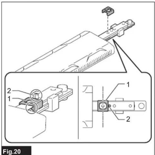
▶ Fig.19: 1. Felt pad 2. Sleeve hole - Turn the shear blades upside down. Attach the rubber dust seal to the shear blades. Adjust its position so the one end of the dust seal touches with the protruding part of the shear blades.
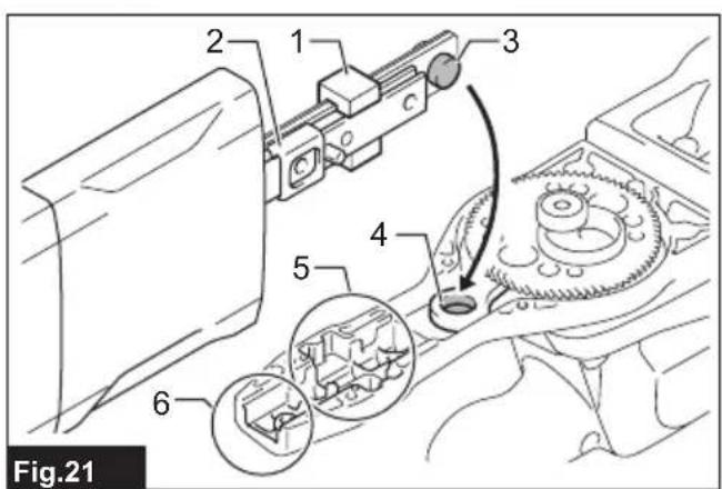
▶ Fig.20: 1. Dust seal 2. Protruding part - Turn the shear blades with the felt pad facing upwards. Align the protruding part of the sear blades with the small end hole in the connecting rod. Assemble the shear blades back in place.
▶ Fig.21: 1. Felt pad 2. Dust seal 3. Protruding part 4. Small end hole 5. Cutouts for felt pad 6. Cutouts for dust seal
NOTICE: Make sure to fit the felt pad and the rubber dust seal well into the cutouts on the blade housing.
NOTICE: Apply a small amount of grease to the inner periphery of the small end hole in the connecting rod.
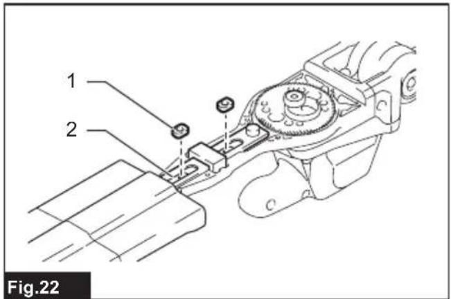
- Place new sleeves into the sleeve holes in the shear blades.
▶ Fig.22: 1. Sleeve 2. Sleeve hole
NOTICE: Be careful not to lose the sleeves.
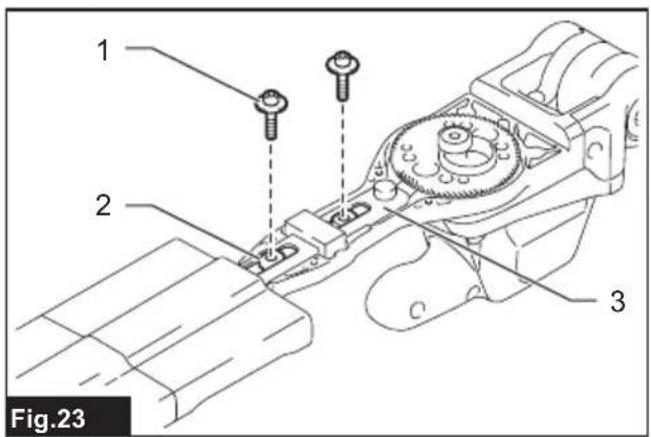
- Align the holes in the sleeves, those in the shear blades and those in the blade housing together along a line. Then tighten the 2 bolts to secure the shear blades.
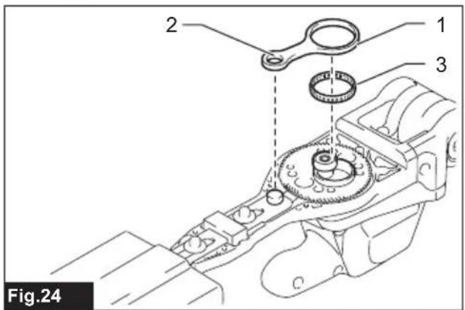
▶ Fig.23: 1. Bolt 2. Sleeve 3. Shear blades - Attach the bearing and the connecting rod.
▶ Fig.24: 1. Connecting rod 2. Small end hole 3. Bearing
NOTICE: Apply a small amount of grease to the inner periphery of the small end hole in the connecting rod.
NOTICE: Make sure to fit the protruding part of the shear blades well into the small end hole in the connecting rod.
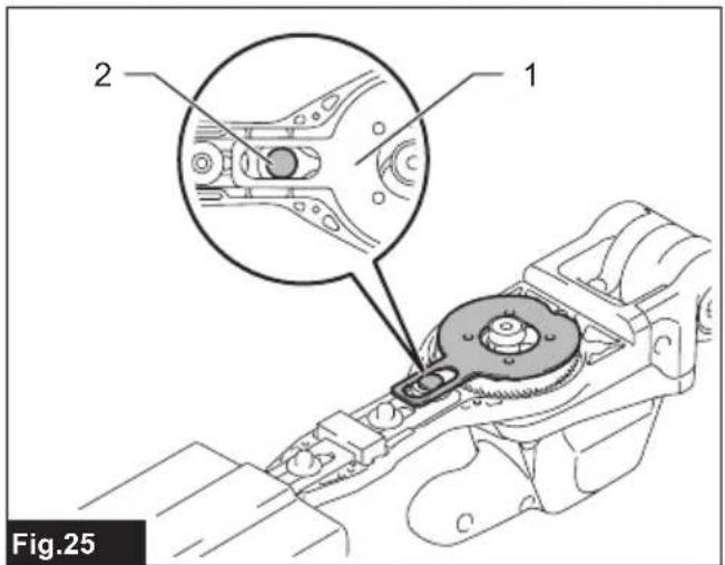
- Assemble the plate back in place.
▶ Fig.25: 1. Plate 2. Protruding part
NOTICE: Make sure to fit the protruding part of the shear blades well into the hole in the plate.
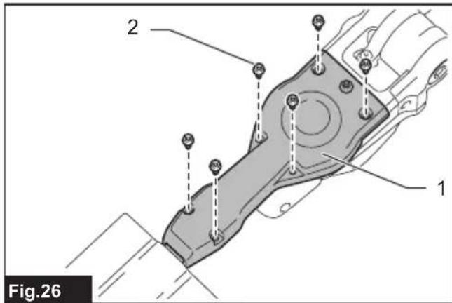
- Attach the cover, and then tighten the 6 bolts.
▶ Fig.26: 1. Cover 2. Bolt
NOTICE: If the shear blades do not move smoothly, the shear blades are not engaged with the connecting rods properly. Install the shear blades again.
NOTICE: If the parts other than the shear blades such as the connecting rods are worn out, ask Makita Authorized Service Centers for parts replacement or repairs.
Installing or removing the chip receiver
Optional accessory
CAUTION: When installing or removing the chip receiver, always wear gloves so that your hands do not directly contact the shear blades.
NOTICE: The blade cover cannot be installed if the chip receiver is installed on the tool. Before carrying or storing the tool, uninstall the chip receiver, and then install the blade cover to avoid blade exposure.
NOTICE: Be sure to remove the blade cover before installing the chip receiver.
The chip receiver gathers discarded leaves and makes clean-up afterward much easier. It can be installed on either side of the tool.
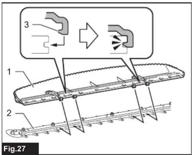
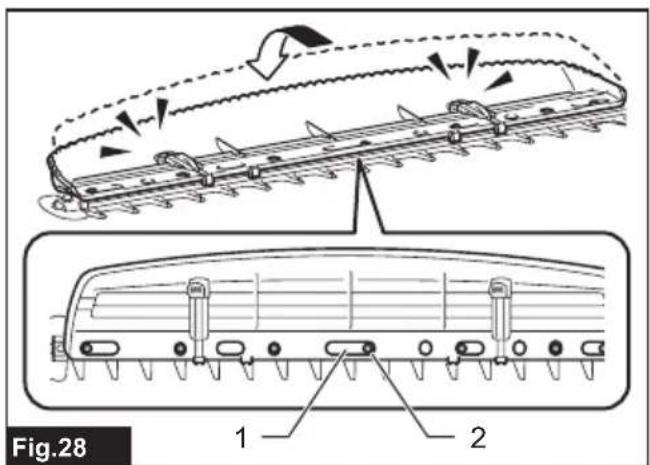
- Hook the claws of the chip receiver to the shear blades.
▶ Fig.27: 1. Chip receiver 2. Shear blades 3. Claw
- Align the holes on the chip receiver with the screws on the shear blades, and then attach the chip receiver to the shear blades securely.
▶ Fig.28: 1. Hole 2. Screw
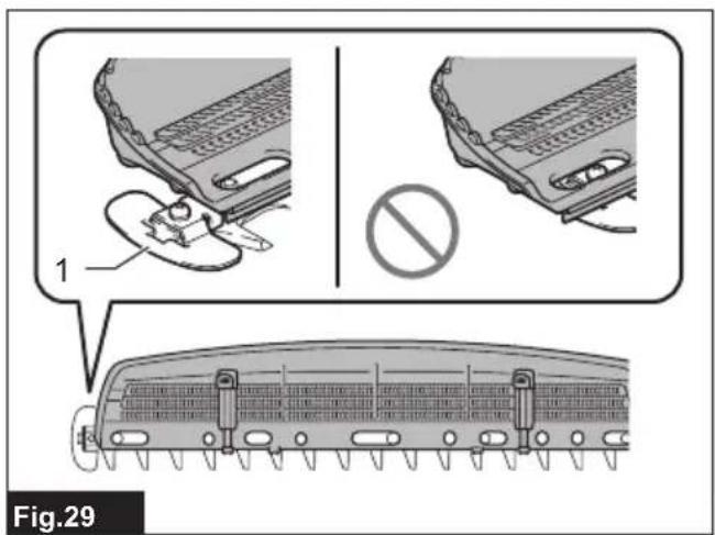
NOTICE: Make sure that the chip receiver does not overlap the branch catcher.
▶ Fig.29: 1. Branch catcher
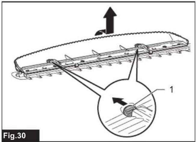
To remove the chip receiver, press the levers to release the claws.
▶ Fig.30: 1. Lever
NOTICE: Never try to remove the chip receiver by an excessive force with its hooks locked in the grooves of the shear blades.
OPERATION
Attaching the shoulder harness
⚠️CAUTION: Before operation, make sure that the shoulder harness is properly attached to the hanger on the tool.
⚠️CAUTION: When you use the tool in combination of the backpack-type power supply such as portable power pack, do not use the shoulder harness included in the tool package, but use the hanging band recommended by Makita.
If you put on the shoulder harness included in the tool package and the shoulder harness of the backpack-type power supply at the same time, removing the tool or backpack-type power supply is difficult in case of an emergency, and it may cause an accident or injury. For the recommended hanging band, ask Makita Authorized Service Centers.
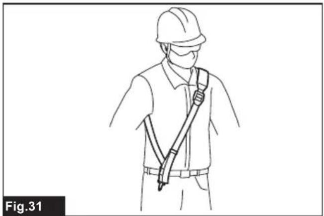
NOTE: Use the shoulder harness attached to the tool. Before operation, adjust the shoulder harness according to the user size to prevent fatigue.
- Wear the shoulder harness on your shoulder.
▶ Fig.31
- Clasp the hook on the shoulder harness to the tool's hanger.
▶ Fig.32: 1. Hook 2. Hanger
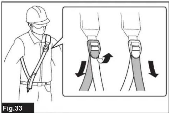
- Adjust the shoulder harness to a comfortable working position.
▶ Fig.33
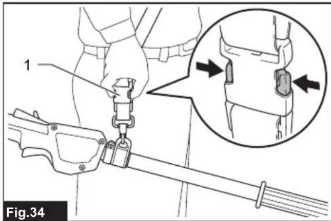
The shoulder harness features a means of quick release.
Simply squeeze the sides of the buckle to release the tool from the shoulder harness.
▶ Fig.34: 1. Buckle
Operating the tool
WARNING: Do not use the tool near any electrical power lines. Contacting with power lines or using the tool near power lines may cause serious injury or electric shock resulting in death.
WARNING: Keep hands away from shear blades.
WARNING: Be extremely careful to maintain control of the tool at all times. Do not allow the tool to be deflected toward you or anyone in the work vicinity. Failure to keep control of the tool could result in serious injury to the bystander and the operator.
CAUTION: Avoid operating the tool in very hot weather as much as practicable. When operating the tool, be careful of your physical condition.
CAUTION: Be careful not to accidentally contact a metal fence or other hard objects while trimming. The shear blades may break and cause an injury.
CAUTION: Be careful not to allow the shear blades to contact the ground. The tool may recoil and cause an injury.
CAUTION: Overreaching with a hedge trimmer, particularly from a ladder, is extremely dangerous. Do not work while standing on anything wobbly or infirm.
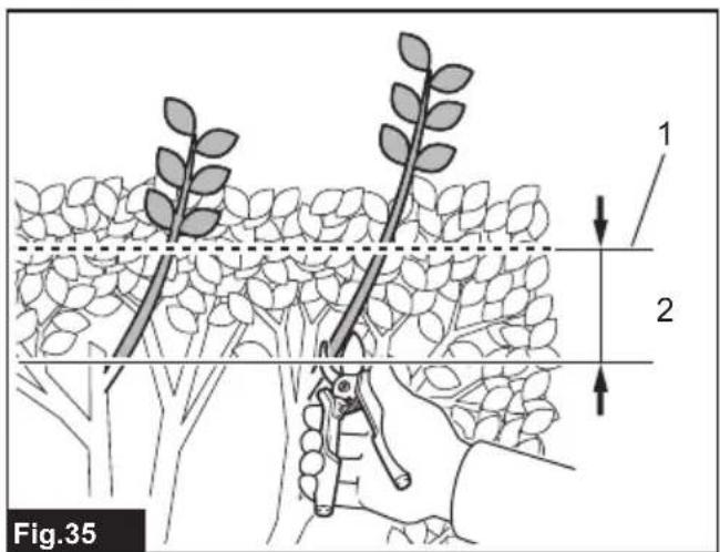
NOTICE: Do not attempt to cut branches thicker than 10 mm in diameter with the tool. Cut branches to 10 cm lower than the cutting height using branch cutters before using the tool.
▶ Fig.35: 1. Cutting height 2. 10 cm
NOTICE: Do not cut down dead trees or similar hard objects. Doing so may damage the tool.
NOTICE: Do not trim the grass or weeds while using the shear blades. The shear blades may become tangled in the grass or weeds.
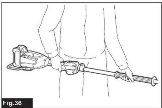
Hold the tool with both hands.
▶ Fig.36
Pull the switch lever while pressing and holding the lock-off lever, and then prepare the tool for trimming.
▶ Fig.37
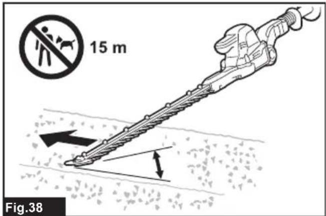
For basic operation, tilt the shear blades toward the trimming direction and move it calmly and slowly at the speed rate of 3 to 4 seconds per meter.
▶ Fig.38
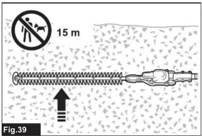
To cut a hedge side evenly, cut from the bottom to top.
▶ Fig.39
When trimming to make a round shape (trimming box-wood or rhododendron, etc.), trim from the root to the top for a beautiful finish.
▶ Fig.40
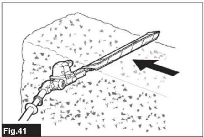
If the chip receiver is attached to the shear blades, it gathers discarded leaves and makes clean-up afterward much easier.
▶ Fig.41
MAINTENANCE
⚠️CAUTION: Always be sure that the tool is switched off and the battery cartridge is removed before attempting to perform inspection or maintenance.
⚠CAUTION: When inspecting or maintaining the tool, always put the tool down. Assembling or adjusting the tool in an upright position may result in serious injury.
To maintain product SAFETY and RELIABILITY, repairs, any other maintenance or adjustment should be performed by Makita Authorized or Factory Service Centers, always using Makita replacement parts.
Cleaning the tool
Clean the tool by wiping off dust with a dry cloth or one dipped in soapy water and wrung out.
NOTICE: Never use gasoline, benzine, thinner, alcohol or the like. Discoloration, deformation or cracks may result.
Shear blades maintenance
Before the operation or once per hour during operation, apply low-viscosity oil (machine oil, or spray-type lubricating oil) to the shear blades.
▶ Fig.42
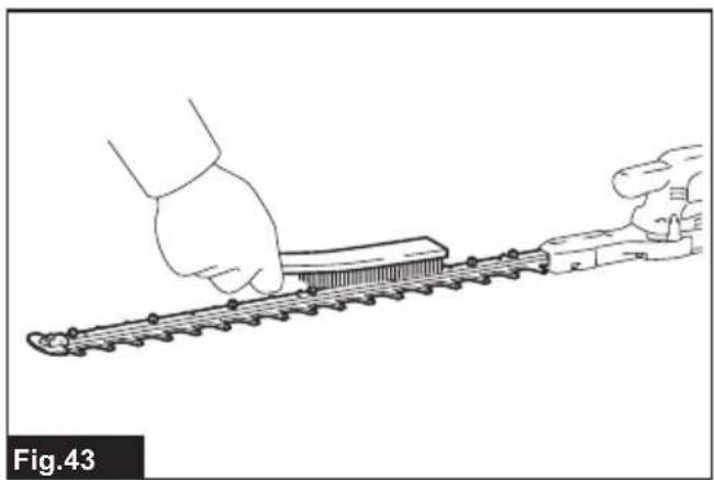
After operation, remove dust from both sides of the shear blades with a wire brush, wipe it off with a cloth and then apply low-viscosity oil (machine oil, or spray-type lubricating oil) to the shear blades.
▶ Fig.43
NOTICE: Do not wash the shear blades in water. Doing so may cause rust or damage to the tool.
NOTICE: Dirt and corrosion cause excessive blade friction and shorten the operating time per battery charge.
Storage
Attach the blade cover to the shear blades so that the blades are not exposed. Store the tool out of the reach of children. Store the tool in a place not exposed to moisture or rain.
Grinding the shear blades
NOTICE: If the shear blades have considerably deformed by grinding, replace the shear blades with new ones.
- Install the battery cartridge to the tool.
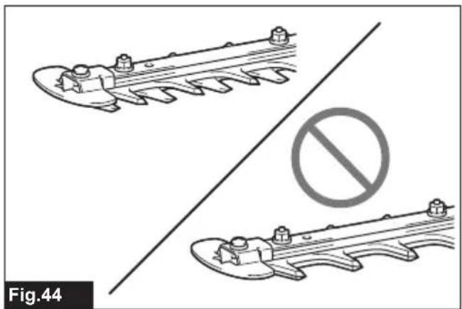
- Turn on and start the tool so that the upper blade and lower blade are positioned shifted to each other.
▶ Fig.44 -
Turn off the tool and remove the battery cartridge from the tool.
-
Remove the screw, and then remove the branch catcher.
▶ Fig.45: 1. Screw 2. Branch catcher - Set the angle of a file to 50^ , and grind the upper blade with the file in exactly the three edge directions.
▶ Fig.46: 1. File 2. 50°
CAUTION: Before grinding the shear blades, make sure that the tool is switched off and the battery cartridge is removed from the tool.
- Place the tool upside down, and then remove the burrs from the shear blade with the dressing stone.
▶ Fig.47: 1. Dressing stone - Set the angle of the file to 50^ , and grind the lower blade with the file in exactly the three edge directions.
- Return the tool to normal position, and then remove the burrs from the shear blade with the dressing stone.
- Attach the branch catcher by tightening the screw.
Grease lubrication
Interval of lubrication: Every 50 operating hours
Using oil hole for lubrication
- Remove the bolt from the hole for lubrication.
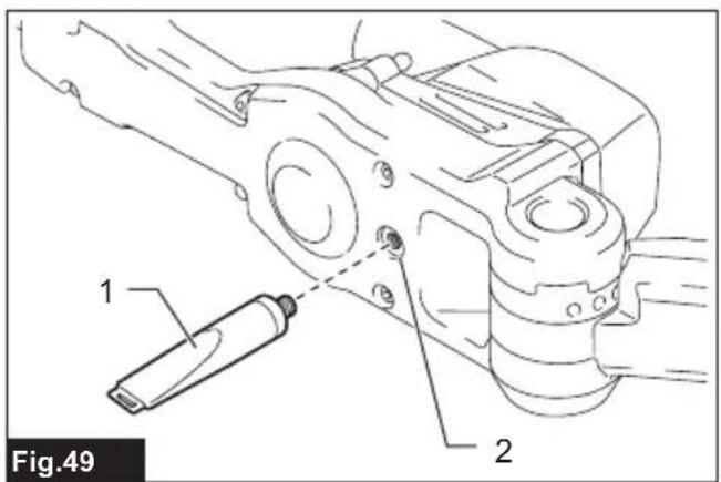
▶ Fig.48: 1. Bolt - Remove the cap from the grease vessel. Align the outlet of the grease vessel with the hole on the cover, and then press the outlet of the grease vessel onto the hole.
▶ Fig.49: 1. Grease vessel 2. Hole - Apply the grease to the tool (Approximately 5 g as a guide).
- Tighten the bolt.
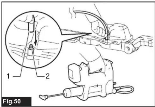
Using grease nipple
The nipple connector helps to connect a grease gun with a positive fit.
- Prepare a grease gun for use.
- Connect the adapter of the grease gun to the grease nipple on the tool.
▶ Fig.50: 1. Grease gun adapter 2. Grease nipple
- Apply the grease to the tool (Approximately 5 g as a guide).
- Tilt the adapter slightly to release internal pressure, and then remove the adapter from the grease nipple.
Wipe off the grease from the adapter and the grease nipple.
TROUBLESHOOTING
Before asking for repairs, conduct your own inspection first. If you find a problem that is not explained in the manual, do not attempt to dismantle the tool. Instead, ask Makita Authorized Service Centers, always using Makita replacement parts for repairs.
| State of abnormality Probable cause | (malfunction) Remedy | |
| Motor does not run. Battery cartridge is | not installed. Install the battery cartridge. | |
| Battery problem (under voltage) Recharge the battery. If recharging is not effective, replace battery. | ||
| The drive system does not work correctly. | Ask your local authorized service center for repair. | |
| Motor stops running after a little use. | Battery's charge level is low. | Recharge the battery. If recharging is not effective, replace battery. |
| Overheating. Stop using of tool to allow it to cool down. | ||
| Tool does not reach maximum RPM. | Battery is installed improperly. | Install the battery cartridge as described in this manual. |
| Battery power is dropping. Recharge the battery. If recharging is not effective, replace battery. | ||
| The drive system does not work correctly. | Ask your local authorized service center for repair. | |
| Shear blades do not move: → stop the machine immediately! | Inappropriate angle of shear blades. Make sure that the head is properly fixed in the operational angle. | |
| Foreign objects are caught between the shear blades. | 1. Use the reverse button.2. Switch off the tool and remove the battery cartridge, and then remove the foreign objects using tools such as pliers. | |
| The drive system does not work correctly. | Ask your local authorized service center for repair. | |
| Abnormal vibration: → stop the machine immediately! | Shear blades are broken, bent or worn. Replace the shear blades. | |
| The drive system does not work correctly. | Ask your local authorized service center for repair. | |
| Shear blades and motor cannot stop: → Remove the battery immediately! | Electric malfunction. | Remove the battery and ask your local authorized service center for repair. |
OPTIONAL ACCESSORIES
⚠️CAUTION: These accessories or attachments are recommended for use with your Makita tool specified in this manual. The use of any other accessories or attachments might present a risk of injury to persons. Only use accessory or attachment for its stated purpose.
If you need any assistance for more details regarding these accessories, ask your local Makita Service Center.
• Shear blades assembly
- Chip receiver
- Grease vessel
• Makita genuine battery and charger
NOTE: Some items in the list may be included in the tool package as standard accessories. They may differ from country to country.
SPÉCIFICATIONS
▶ Fig.10: 1. Tête 2. Manchon coulissant
▶ Fig.20: 1. Joint anti-poussière 2. Partie saillante
▶ Fig.25: 1. Plaque 2. Partie saillante
▶ Fig.29: 1. Attrape-branches
▶ Fig.45: 1. Vis 2. Attrape-branches
▶ Fig.46: 1. Lime 2. 50°
▶ Abb.46: 1. Feile 2. 50°
▶ Abb.47: 1. Abziehstein
▶ Abb.49: 1. Fetttube 2. Loch
⚠ WAARSCHUWING: Draag gehoorbescherming.
VEILIGHEIDSWAAR- SCHUWINGEN
▶ Fig.27: 1. Snoeiafvalvanger 2. Messenbladen 3. Klauw
▶ Fig.28: 1. Gat 2. Schroef
▶ Fig.46: 1. Vijl 2. 50°
OPTIONELE ACCESSOIRES
▶ Fig.26: 1. Tampa 2. Parafuso

- Applicable battery cartridge and charger
- Recommended cord connected power source
- Noise
- Vibration
- Declarations of Conformity
- SAFETY WARNINGS
- General power tool safety warnings
- Save all warnings and instructions for future reference.
- Cordless pole hedge trimmer safety warnings
- Cordless pole hedge trimmer safety warnings:
- Additional Safety Warnings
- Preparation
- Personal protective equipment
- Operation
- Electrical and battery safety
- Maintenance and storage
- SAVE THESE INSTRUCTIONS.
- Important safety instructions for battery cartridge
- Tips for maintaining maximum battery life
- PARTS DESCRIPTION
- FUNCTIONAL DESCRIPTION
- Installing or removing battery cartridge
- Indicating the remaining battery capacity
- Tool / battery protection system
- Overload protection
- Overheat protection for tool or battery
- Overdischarge protection
- Protections against other causes
- Power switch action
- Speed adjusting
- Reverse button for debris removal
- Adjusting the cutting angle
- Electronic function
- ASSEMBLY
- Installing or removing the shear blades
- Attaching the shoulder harness
- Operating the tool
- MAINTENANCE
- Cleaning the tool
- Shear blades maintenance
- Storage
- Grinding the shear blades
- Grease lubrication
- Using oil hole for lubrication
- Using grease nipple
- TROUBLESHOOTING
- OPTIONAL ACCESSORIES
- VEILIGHEIDSWAAR- SCHUWINGEN
- ▶ Fig.46: 1. Vijl 2. 50°
- OPTIONELE ACCESSOIRES
Brand : MAKITA
Model : UN001G
Category : Hedge trimmers