
CVMAD601N1 - Range hood CANDY - Free user manual and instructions
Find the device manual for free CVMAD601N1 CANDY in PDF.
| Product Type | Range hood |
| Brand | Candy |
| Model | CVMAD601N1 |
| Category | Hood |
| Power Supply | AC 110-240 V |
| Lighting Power | 2 x LED 2 W (type DBR-2/65-H-64) |
| Motor Speeds | 3 speeds (Low, Medium, High) + Stop |
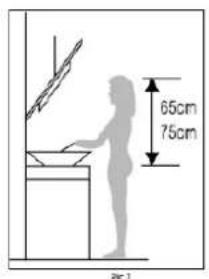
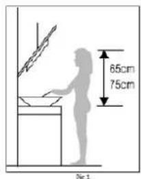
| Minimum Installation Distance | Gas stove: 75 cm; Electric: 65 cm |
| Exhaust Duct Diameter | 150 mm (inner) |
| Grease Filters | Metal mesh filters (washable) |
| Activated Carbon Filter | Optional, replacement every 3 to 6 months |
| Features | Stop, Low, Medium, High, Lighting |
| Maintenance and Cleaning | Clean stainless steel with soft cloth; grease filters: soapy water |
| Safety | Auto shut-off not mentioned; backdraft damper; secure mounting |
| Spare Parts and Repairability | LED bulbs replaceable by professional; filters available |
| General Information | Installation by qualified electrician; comply with exhaust standards |
Frequently Asked Questions - CVMAD601N1 CANDY
User questions about CVMAD601N1 CANDY
0 question about this device. Answer the ones you know or ask your own.
Ask a new question about this device
Download the instructions for your Range hood in PDF format for free! Find your manual CVMAD601N1 - CANDY and take your electronic device back in hand. On this page are published all the documents necessary for the use of your device. CVMAD601N1 by CANDY.
USER MANUAL CVMAD601N1 CANDY
CVMAD60/1N/1, CVMAD60/1B/1
Cooker Hood
Instruction Manual
ENGLISH (EN)......page 001
CZECH (CS)......page 013
SPANISH (ES)......page 025
FRENCH (FR)......page 037
GREEK (GR) ......page 049
CROATIAN (HR)......page 061
SLOVENIAN (SL) ......page 073
SLOVAK (SK) ......page 085
HUNGARIAN (HU)......page 097
Cooker Hood Instruction Manual
Content
- Safety instructions
2....Installation
3....Start using your cooker hood
4....Troubleshooting
5....Maintenance and cleaning
6 Environment protection
SAFETY INSTRUCTIONS
This manual explains the proper installation and use of your cooker hood, please read it carefully before using even if you are familiar with the product. The manual should be kept in a safe place for future reference.
Never to do:
- Do not try to use the cooker hood without the grease filters or if the filters are excessively greasy!
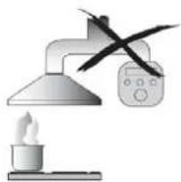
- Do not install above a cooker with a high level grill.
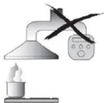
- Do not leave frying pans unattended during use because overheated fats or oils might catch fire.
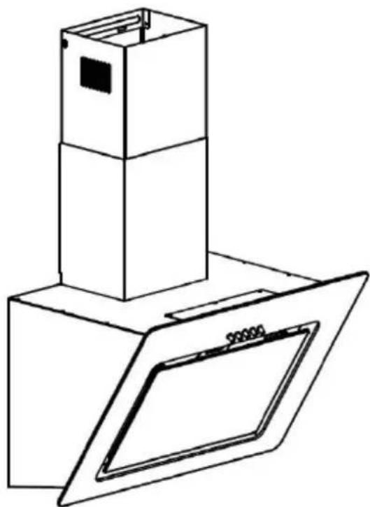
● Never leave naked flames under the cooker hood.
- If the cooker hood is damaged, do not attempt to use.
● Do not flambé under the cooker hood.
● CAUTION: Accessible parts may become hot when used with cooking appliances.
● The minimum distance between the supporting surface for the cooking vessels on the hob and the lowest part of the cooker hood. (When the cooker hood is located above a gas appliance, this distance shall be at least 65 cm)
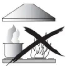
● The air must not be discharged into a flue that is used for exhausting fumes from appliances burning gas or other fuels.
Always to do:
- Important! Always switch off the electricity supply at the mains during installation and maintenance such as light bulb replacement.
● The cooker hood must be installed in accordance with the installation instructions and all measurements followed.
● All installation work must be carried out by a competent person or qualified electrician.
● Please dispose of the packing material carefully. Children are vulnerable to it.
● Pay attention to the sharp edges inside the cooker hood especially during installation and cleaning. - When the cooker hood is located above a gas appliance, the minimum distance between the supporting surface for the cooking vessels on the hob and the lowest part of the cooker hood that distance must be:
Gas cookers: 75 cm
Electric cookers: 65 cm
Coal or oil cookers: 75 cm
● Make sure the ducting has no bends sharper than 90 degrees as this will reduce the efficiency of the cooker hood.
● Warning: Failure to install the screws or fixing device in accordance with these instructions may result in electrical hazards
Always to do:
● Always put lids on pots and pans when cooking on a gas cooker.
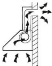
- When in extraction mode, air in the room is being removed by the cooker hood. Please make sure that proper ventilation measures are being observed. The cooker hood removes odours from room but not steam.
● Cooker hood is for domestic use only.
- If the supply cord is damaged, it must be replaced by the manufacturer, its service agent or similarly qualified persons in order to avoid a hazard.
● This appliance can be used by children aged from 8 years and above and persons with reduced physical, sensory or mental capabilities or lack of experience and knowledge if they have been given supervision or instruction concerning use of the appliance in a safe way and understand the hazards involved. Children shall not play with the appliance. Cleaning and user maintenance shall not be made by children without supervision.

● Warning: Before obtaining access to terminals, all supply circuits must be disconnected.
Always to do:
● Caution: The appliance and its accessible parts can become hot during operation. Be careful to avoid touching the heating elements. Children younger than 8 years old should stay away unless they are under permanent supervision.
● There shall be adequate ventilation of the room when the cooker hood is used at the same time as appliances burning gas or other fuels.
● There is a fire risk if cleaning is not carried out in accordance with the instructions
● Regulations concerning the discharge of air have to be fulfilled.
● Clean your appliance periodically by following the method given in the chapter MAINTENANCE.
● For safety reason, please use only the same size of fixing or mounting screw which are recommended in this instruction manual.
● Regarding the details about the method and frequency of cleaning, please refer to maintenance and cleaning section in the instruction manual.
● Cleaning and user maintenance shall not be made by children without supervision.
- When the cooker hood and appliances supplied with energy other than electricity are simultaneously in operation, the negative pressure in the room must not exceed 4 Pa (4 x 10⁻⁵ bar).
●WARNING: Danger of fire: do not store items on the cooking surfaces.
●A steam cleaner is not to be used.
● NEVER try to extinguish a fire with water, but switch off the appliance and then cover flame e.g. with a lid or a fire blanket.
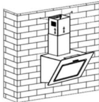
INSTALLATION (VENT OUTSIDE)
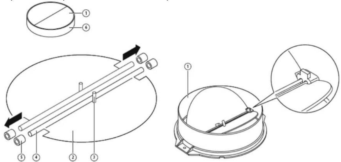
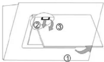
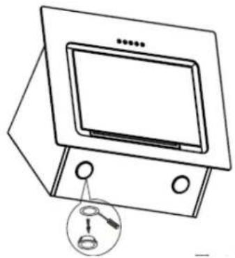
MOUNTING OF THE V-FLAP
If the cooker hood does not have an assembled V-flap 1, you should mount the half-parts to its body. The images only show an example of how to mount the V-flap, the outlet may be various according to different models and configuration.
To mount the V-flap 1 you should:
- Mount two half-parts 2 into the body 6
- a pin 3 should be top oriented;
- the axis 4 should be inserted in the holes 5 on body;
- repeat all the operations for the 2nd half-part
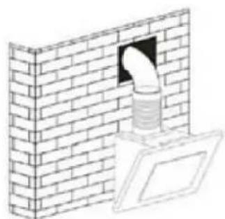
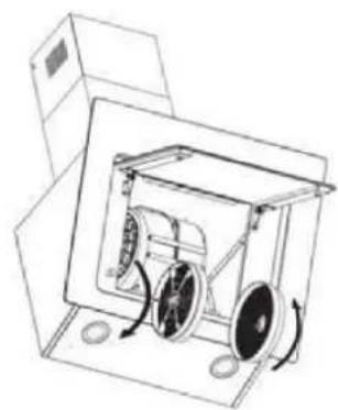
INSTALLATION
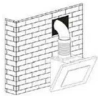
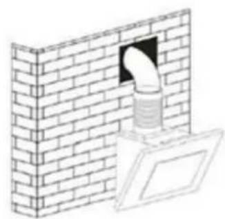
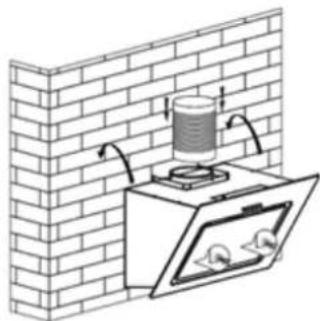
If you have an outlet to the outside, your cooker hood can be connected as below picture by means of an extraction duct (enamel, aluminum, flexible pipe or inflammable material with an interior diameter of 150mm)
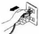
- Before installation, turn the unit off and unplug it from the outlet.

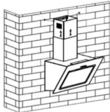
- The cooker hood should be placed at a distance of 65\~75cm above the cooking surface for best effect.
- Using a drill bit with an 8 mm diameter, make 8 holes in the wall at the position that you reserve for installing the chimney and cooker hood body. See Pic 2.
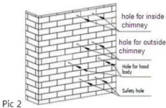
- Insert wall plugs into the holes that you have drilled for the cooker hood body, fasten
2 × support screw ST4*40 mm halfway in, leaving them 2 mm out of the wall. See Pic 2. - Hang the cooker hood onto the support screws. See pic 3.
- Insert self-tap screw ST4*30 mm into the safety holes and fully fasten it to ensure the cooker hood is well fixed. See pic 3.

Pic 3
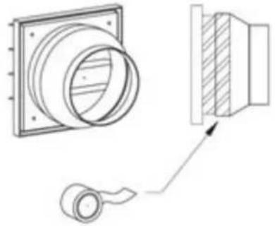
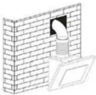
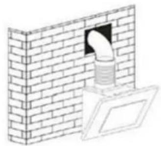
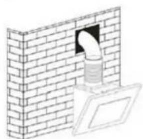
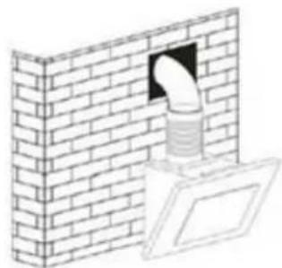
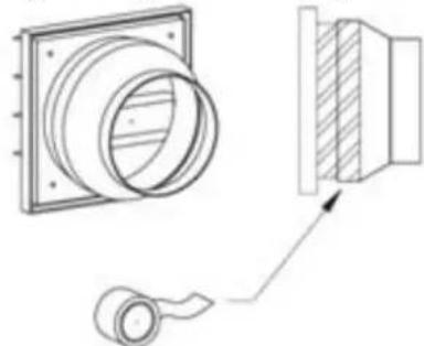
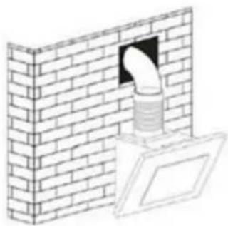
- Equip the converter to the one-way-valve, and fix by tape(Pic below). Install the 120mm expansion pipe to the outlet converter and fixed by cable tie. Lift up expansion pipe till it out of the wall through the hole on the wall.
Pic 4
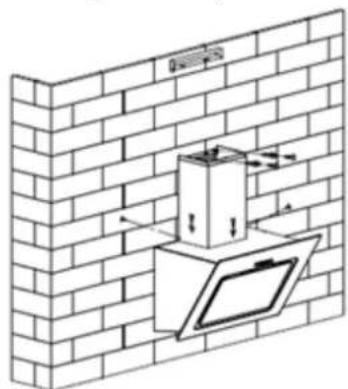
- Install the inside chimney bracket: Use ST4*40 screws to install the inside chimney bracket onto the wall. See Pic 5.
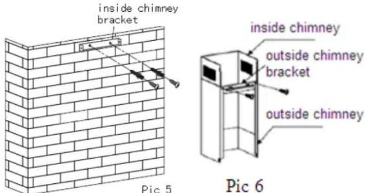
- Equip the inside chimney and outside chimney: Install the outside chimney bracket on the outside chimney by 2pcs ST4*8mm screws, make sure that the inside chimney could be moved inside freely, see Pic 6.
- Fix the chimneys onto the cooker hood: Use 2pcs of ST4*8mm screws to fix the outside chimney bracket onto the cooker hood bracket, then fix the outside chimney bracket on the wall by ST4*40mm screws. See Pic 7.

Pic 7

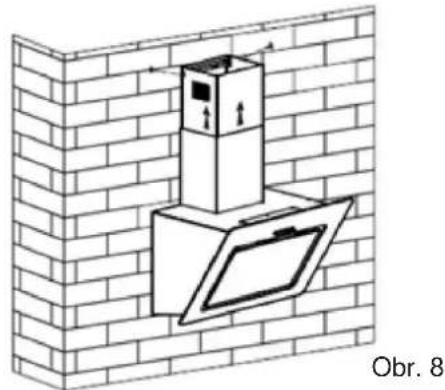
Pic 8
- Adjust the height of the inside chimney to the position of the inside chimney bracket and fix on it by 2pcs ST4*8mm screws. See Pic 8.
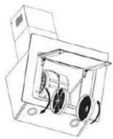
Note: The two safety vents are positioned on the back housing, with diameter of 6mm.
HINTS FOR EXHAUST DUCT INSTALLATION
The following rules must be strictly followed to obtain optimal air extraction:
- Keep exhaust duct short and straight
- Do not reduce the size or restrict exhaust duct
- When using flexible duct always install the duct pulled taut to minimize pressure loss
- Failure to observe these basic instructions will reduce the performance and increase noise levels of the cooker hood.
- Any installation work must be carried out by a qualified electrician or competent person.
- Do not connect the ducting system of the hood to any existing ventilation system which is being used for any other appliance, such as warmer tube, gas tube, hot wind tube.
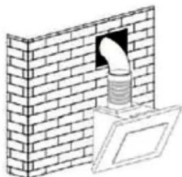
•The angle of the bend of the ventilation pipe should not be less than 120° ; you must direct the pipe horizontally, or, alternatively, the pipe should go up from the initial point and should be led to an outer wall.
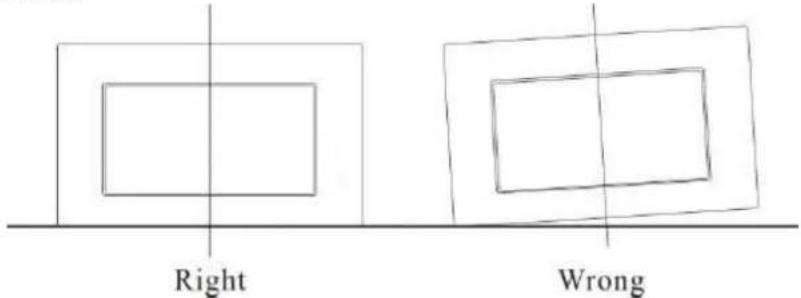
•After the installation, make sure that the cooker hood is level to avoid grease collection at on end.
Ensure the exhaust ducting selected for installation complies with relevant standards and is fire retardant.
WARNING:
For safety reason, please use only the sa size of fixing or mounting screw which are recommended in this instruction manual.
Failure to install the screws or fixing device in accordance with these instructions may re set in electrical hazards.
Start Using Your Cooker Hood
Push button
a. Press the button "Stop", the motor is stopped then.
b. Press the button "Low", the motor is running at low speed.
c. Press the button "Mid", the motor is running at medium speed.
d. Press the button "High", the motor is running at high speed.
e. Press the button "Light", both lights start shining .Press the button again; the lights are switched off then.

Stop

Low

Mid

High

Lamp
TROUBLESHOOTING
| Fault | Possible Cause | Solution |
| Light on, but motor does not work | Fan switch turned off Select a fan switch position. | |
| Fan switch failed | Contact service center. | |
| Motor failed Contact service center. | ||
| Light does not work, motor does not work | House fuses blown Reset/Replace fuses. | |
| Power cord loose or disconnected | Refit cord to power outlet.Switch power outlet on. | |
| Oil leakage | One way valve and the outlet are not tightly sealed | Take down the one way valve and seal with sealant. |
| Leakage from the connection of chimney and cover | Take chimney down and seal. | |
| Lights not working | Broken/Faulty globes | Replace globes as per this instruction. |
| Insufficient suction | The distance between the cooker hood and the gas top is too far | Refit the cooker hood to the correct distance. |
| The Cooker hood inclines | The fixing screw not tight enough | Tighten the hanging screw and make it horizontal. |
NOTE:
Any electrical repairs to this appliance must conform to your local, state and federal laws. Please contact the service centre if in any doubt before
undertaking any of the above. Always disconnect the unit from the power source when opening the unit.
MAINTENANCE AND CLEANING
Caution:
- Before maintenance or cleaning is carried out, the cooker hood should be disconnected from the main power supply. Ensure that the cooker hood is switched off at the wall socket and the plug removed.
- External surfaces are susceptible to scratches and abrasions, so please follow the cleaning instructions to ensure the best possible result is achieved without damage.
GENERAL
Cleaning and maintenance should be carried out with the appliance cold especially when cleaning. Avoid leaving alkaline or acid substances (lemon juice, vinegar etc.) on the surfaces.
STAINLESS STEEL
The stainless steel must be cleaned regularly (e.g.weekly) to ensure long life expectancy.Dry with a clean soft cloth. A specialized stainless steel cleaning fluid may
be used.
NOTE:
Ensure that wiping is done along with the grain of the stainless steel to prevent any unsightly crisscross scratching patterns from appearing.
CONTROL PANEL SURFACE
The inlay control panel can be cleaned using warm soapy water. Ensure the cloth is clean and well wrung before cleaning. Use a dry soft cloth to remove any excess moisture left after cleaning.
Important
Using neutral detergents and avoid using harsh cleaning chemicals, strong household detergents or products containing abrasives, as this will affect the appliance appearance and potentially remove any printing of artwork on the control panel and will void manufactures warrantee.
GREASE MESH FILTERS
The mesh filters can be cleaned by hand. Soak them for about 3 minute in water with a grease-loosening detergent then brush it gently with a soft brush. Please do not apply too much pressure, avoid to damage it. (Leave to dry naturally out of direct sun light)
Filters should be washed separately to crockery and kitchen utensils. it is advisable not to use rinse aid.
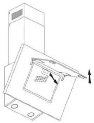
INSTALLING GREASE MESH FILTERS
- To install filters for the following four steps (See pic beside):
- Angle the filter into slots at the back of the hood.
- Push the button on handle of the filter.
- Release the handle once the filter fits into a resting position.
- Repeat to install all filters.
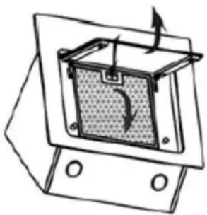
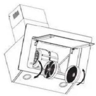
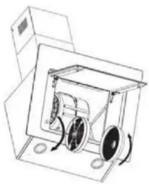
CARBON FILTER
Activated carbon filter can be used to trap odors. Normally the activated carbon filter should be changed at three or six months according to your cooking habit. The installation procedure of activated carbon filter is as below.
- Before installing or replacing the carbon filters, please remove power to the unit.
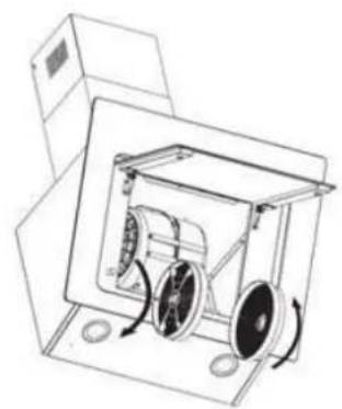
- Press the filter lock and remove the mesh filter.
- Turn the carbon filter on both side of the motor anti-clockwise. Replace the carbon filters with the new carbon filters.
- Place the mesh filter.
- Connect the power supply to the wall socket.

NOTE:
- Make sure the filter is securely locked. Otherwise, it would loosen and cause dangerous.
- When activated carbon filter attached, the suction power will be lowered.
BULB REPLACEMENT
Important :

The bulb must be replaced by the manufacturer, its service agent or similarly qualified persons.
Always switch off the electricity supply carrying out any operations on the appliance. When handling bulb, make sure it is completely cool down before any direct contact to hands.
When handling globes hold with a cloth or gloves to ensure perspiration does not come in contact with the globe as this can reduce the life of the globe.
LED LIGHTS:
- Switch the unit off and pull out the plug first.
- Wait until the light bulb is cooled down before replacement.
- Remove the front part with the aid of screwdriver.
- Pull out the LED light carefully and replace with the same type and rated LED light (2*2W LSD-B2 LED light)
- Replace the front part back to the unit with screwdriver.
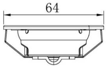
• ILCOS D code for this lamp is: DBR-2/65-H-64 - LED modules, self- ballasted - round lamp
- Max wattage: 2 W
– Voltage range: AC 110-240V - Dimensions:
ENVIRONMENTAL PROTECTION:

This appliance is labelled in accordance with European Directive 2012/19/EU on Waste Electrical and Electronic Equipment Regulations 2013 regarding electric and electronic appliances (WEEE). The WEEE contain both polluting substances (that can have a negative effect on the environment) and base elements (that can be reused). It is important that the WEEE undergo specific treatments to correctly remove and dispose of the pollutants and recover all the materials. Individuals can play an important role in ensuring that the WEEE do not become an environmental problem; it is essential to follow a few basic rules: - the WEEE should not be treated as domestic waste; - the WEEE should be taken to dedicated collection areas managed by the town council or a registered company. In many countries, domestic collections may be available for large WEEEs. When you buy a new appliance, the old one can be returned to the vendor who must accept it free of charge as a one-off, as long as the appliance is of an equivalent type and has the same functions as the purchased appliance.
NOTE:
The following shows how to reduce total environmental impact (e.g. energy use) of the cooking process).
(1) Install the cooker hood in a proper place where there is efficient ventilation.
(2) Clean the cooker hood regularly so as not to block the airway.
(3) Remember to switch off the cooker hood light after cooking.
(4) Remember to switch off the cooker hood after cooking.
INFORMATION FOR DISMANTLING
Do not dismantle the appliance in a way which is not shown in the user manual. The appliance could not be dismantled by user. At the end of life, the appliance should not be disposed of with household waste. Check with you Local Authority or retainer for recycling advice.
Obsah
Co je vždy nutné:
MONTÁŽ KLÍNOVÉ KLAPKY
INSTALACE
Pic 3
Pic 4
Pic 7

Pic 8
INSTALACE MŘÍŽKOVÝCH TUKOVÝCH FILTRŮ
UHLÍKOVÝ FILTR

POZNÁMKA:
OCHRANA ŽIVOTNÍHO PROSTŘEDÍ

Índice
INSTALACIÓN
Pic 3
Pic 4+
Pic 7

Pic 8
FILTRO DE CARBONO
NOTA:
Sommaire
À toujours faire :
INSTALLATION
Pic 3
Pic 4+
Pic 7
Pic 8
FILTRE À CHARBON
REMARQUE :

Περιεχόμενα
ΕΓΚΑΤΑΣΤΑΣΗ
Pic 3
Pic 4
Pic 7
Pic 8
ΦΙΛΤΡΟ ΑΝΘΡΑΚΑ
ΣΗΜΕΙΩΣΗ:
Sadržaj
1.....Sigurnosne upute
2....Ugradnja
3....Počnite rabiti napu za štednjak
4....Rješavanje problema
5. Održavanje i čišćenje
6....Zaštita okoliša
SIGURNOSNE UPUTE
U ovom priručniku opisane su pravilna ugradnja i uporaba vaše nape za štednjak; pažljivo ga pročitajte prije uporabe čak i ako vam je proizvod poznat. Priručnik treba čuvati na sigurnom mjestu da biste se njime mogli poslužiti i u budućnosti.
- Ako je napa za štednjak oštećena, ne pokušavajte je rabiti.
- Ne flambirajte hranu ispod nape za štednjak.
- OPREZ: Prilikom uporabe s uređajima za kuhanje dostupni dijelovi mogu se zagrijati.
- Najmanja udaljenost između potporne površine za posude za kuhanje na ploči za kuhanje i najnižeg dijela nape za štednjak. (Kada je napa za štednjak smještena iznad plinskog uređaja, ta udaljenost mora biti najmanje 65 cm)
- Zrak se ne smije ispustiti u dimnjak koji se rabi za ispušne plinove uređaja na plin ili druga goriva.
UGRADNJA
- Prije ugradnje ugasite jedinicu i isključite je iz utičnice.
- Napu za štednjak treba postaviti na udaljenost od 65 do 75 cm iznad površine za kuhanje radi najboljih rezultata.
-
Umetnite zidne zatike u rupe koje ste izbušili za tijelo nape za štednjak, pričvrstite dva potporna vijka ST4*40 mm napola unutra, tj. neka 2 mm bude izvan zida. Pogledajte SI. 2.
-
Objesite napu za štednjak na potporne vijke. Pogledajte Sl. 3.
-
Umetnite vijak za samonarezivanje unutarnjih navoja ST4*30 mm u sigurnosne rupe i potpuno ga pričvrstite da biste osigurali da je napa za štednjak dobro pričvršćena. Pogledajte sliku 3.
Pic 3
Pic 4+
- Opremite unutarnji dimnjak i vanjski dimnjak: Ugradite nosač za vanjski dimnjak na vanjski dimnjak dvama vijcima ST4*8 mm, pobrinite se da se unutarnji dimnjak unutra može slobodno pomicati, pogledajte SI. 6.
- Pričvrstite dimnjake na napu za štednjak: upotrijebite dva vijka ST4*8 mm da biste pričvrstili nosač za vanjski dimnjak na nosač nape za štednjak, a zatim pričvrstite nosač za vanjski dimnjak na zid vijcima ST4*40 mm. Pogledajte Sl. 7.
Pic 7

Pic 8
Iz sigurnosnih ra zloga up otrebljavajte sam onu veličinu pričvrsnih ili postavnih vijaka koja je preporučena u ovom priručniku s uputama.
Ako ne ugradi te vi jke ili p ričvrsni uređaj u skladu s ovi m u putama, mogu na stati povezani sa strujom.
Počnite rabiti napu za štednjak
Gumb za pritiskanje
a. Pritisnite gumb „Stop“, motor se zaustavlja.
b. Pritisnite gumb „Malo“, motor radi pri maloj brzini.
c. Pritisnite gumb „Srednje“, motor radi pri srednjoj brzini.
d. Pritisnite gumb „Veliko“, motor radi pri velikoj brzini.
e. Pritisnite gumb „Svjetlo“, pale se oba svjetla. Pritisnite gumb opet i svjetla se gase.

Stop

Low

Mid

High

Lamp
| Kvar | Mogući uzrok | Rješenje |
| Svjetlo je uključeno, ali motor ne radi | Isključen je prekidač za ventilator | Odaberite položaj prekidača za ventilator. |
| Kvar prekidača za ventilator | Obratite se servisnom centru. | |
| Kvar motora | Obratite se servisnom centru. | |
| Svjetlo ne radi, motor ne radi | Izgorjeli osigurači | Vratite osigurače u prvotno stanje / zamijenite ih. |
| Kabel za napajanje labav ili nije spojen | Ponovno utaknite kabel u utičnicu.Uključite utičnicu. | |
| Curenje ulja | Jednosmjerni ventil i otvor nisu čvrsto zatvoreni | Spustite jednosmjerni ventil i zabrtvite ga brtvilom. |
| Curenje iz spoja dimnjaka i poklopca | Spustite dimnjak i zabrtvite ga. | |
| Svjetla ne rade | Razbijene žarulje / žarulje u kvaru | Zamijenite žarulje prema ovojuputi. |
| Nedovoljan usis | Prevelika udaljenost između nape za štednjak i plinske ploče | Postavite napu za štednjak na pravilnu udaljenost. |
| Naginje se napa za štednjak | Pričvrsni vijak nije dovoljno stegnut | Stegnite viseći vijak i stavite ga u vodoravan položaj. |
NAPOMENA:

Bilo koji električni popravci ovoga uređaja moraju biti u skladu s lokalnim, državnim i saveznim zakonima. Obratite se servisnom centru ako imate
- Vanjske su površine podložne ogrebotinama i abraziji; stoga se pridržavajte uputa za čišćenje da biste postigli najbolje rezultate bez oštećenja.
OPĆENITO
UGRADNJA FILTARA S MREŽICOM ZA MASNOĆE
UGLJENI FILTAR
Filtar od aktivnog ugljena može se upotrijebiti za sprječavanje širenja neugodnih mirisa. Filtar od aktivnog ugljena normalno treba promijeniti nakon tri do šest mjeseci, ovisno o vašim navikama kuhanja. Postupak ugradnje filtra od aktivnog ugljena objašnjen je u nastavku.
- Prije ugradnje ili zamjene ugljenih filtara isključite napajanje jedinice.
- Pritisnite zapinjač filtra i izvucite filtar s mrežicom.
- Okrećite ugljeni filtar u smjeru suprotnom od kazaljke na satu na obje strane motora. Zamijenite ugljene filtre novim ugljenim filtrima.
- Stavite filtar s mrežicom.
- Pokrenite napajanje strujne utičnice.


NAPOMENA:
ZAŠTITA OKOLIŠA:

Ovaj uređaj označen je u skladu s Europskom direktivom 2012/19/EU o otpadnoj električnoj i elektroničkoj opremi iz 2013. godine o električnim i elektroničkim uređajima (OEEO). OEEO obuhvaća i zagađujuće materije (koje mogu negativno utjecati na okoliš) i osnovne komponente (koje se mogu ponovo upotrebljavati). Važno je da se OEEO podvrgne posebnim tretmanima, u cilju pravilnog otklanjanja i odlaganja svih zagađivača, kao i vraćanju i recikliranju svih materijala. Pojedinci mogu imati važnu ulogu osiguravanjem da OEEO ne postane ekološki problem; potrebno je slijediti nekoliko osnovnih pravila: - OEEO se ne smije smatrati kućanskim otpadom. - OEEO se predaje mjestima nadležnim za prikupljanje takvog otpada kojima upravljaju općina ili registrirana tvrtka. U mnogim zemljama, za velike OEEO-ove omogućeno je sakupljanje kod kuće. Kada kupite novi uređaj, možete vratiti stari trgovcu koji ga mora preuzeti besplatno, u okviru zamjene jedan za jedan; ako se radi o uređaju iste vrste koji je imao iste funkcije kao i uređaj koji se isporučuje.
NAPOMENA:
Vsebina
Vedno:
- Opozorilo: Preden dostopate do terminalov, morate izključiti vsa napajanja.
Vedno:
NAMESTITEV
Pic 3
- Pretvornik povežite z enosmernim ventilom in ga fiksirajte s trakom (slika spodaj). Namestite 120 mm raztezno cev na izhod pretvornika in jo fiksirajte z vezico. Raztezno cev dvignite in jo skozi luknjo v steni potisnite skozi steno.
Pic 4
Pic 7

Pic 8
- Prilagodite višino notranjega odvoda položaju notranjega nosilca odvoda in ga fiksirajte z 2 vijakom ST4*8 mm. Glej sl. 8
NAMEŠČANJE MREŽASTEGA MAŠČOBNEGA FILTRA
FILTER Z OGLJEM

OPOMBA:
VARSTVO OKOLJA:
Obsah
INŠTALÁCIA
Obr. 4
INŠTALÁCIA DRÔTENÝCH TUKOVÝCH FILTROV
UHLÍKOVÝ FILTER
POZNÁMKA:
OCHRANA ŽIVOTNÉHO PROSTREDIA:
Tartalom
TELEPÍTÉS
- ábra
SZÉNSZÜRÓ
MEGJEGYZÉS:
KÖRNYEZETVÉDELEM:


- CVMAD60/1N/1, CVMAD60/1B/1
- COOKER HOOD
- INSTRUCTION MANUAL
- COOKER HOOD INSTRUCTION MANUAL
- CONTENT
- SAFETY INSTRUCTIONS
- NEVER TO DO
- ALWAYS TO DO
- INSTALLATION (VENT OUTSIDE)
- MOUNTING OF THE V-FLAP
- INSTALLATION
- HINTS FOR EXHAUST DUCT INSTALLATION
- WARNING
- START USING YOUR COOKER HOOD
- PUSH BUTTON
- TROUBLESHOOTING
- NOTE
- MAINTENANCE AND CLEANING
- CAUTION
- GENERAL
- STAINLESS STEEL
- CONTROL PANEL SURFACE
- IMPORTANT
- GREASE MESH FILTERS
- INSTALLING GREASE MESH FILTERS
- CARBON FILTER
- BULB REPLACEMENT
- LED LIGHTS
- ENVIRONMENTAL PROTECTION
- INFORMATION FOR DISMANTLING
- OBSAH
- CO JE VŽDY NUTNÉ
- MONTÁŽ KLÍNOVÉ KLAPKY
- INSTALACE
- INSTALACE MŘÍŽKOVÝCH TUKOVÝCH FILTRŮ
- UHLÍKOVÝ FILTR
- POZNÁMKA
- OCHRANA ŽIVOTNÍHO PROSTŘEDÍ
- ÍNDICE
- INSTALACIÓN
- FILTRO DE CARBONO
- NOTA
- SOMMAIRE
- À TOUJOURS FAIRE
- FILTRE À CHARBON
- REMARQUE
- ΠΕΡΙΕΧΌΜΕΝΑ
- ΕΓΚΑΤΑΣΤΑΣΗ
- ΦΙΛΤΡΟ ΑΝΘΡΑΚΑ
- ΣΗΜΕΙΩΣΗ
- SADRŽAJ
- SIGURNOSNE UPUTE
- UGRADNJA
- POČNITE RABITI NAPU ZA ŠTEDNJAK
- GUMB ZA PRITISKANJE
- NAPOMENA
- OPĆENITO
- UGRADNJA FILTARA S MREŽICOM ZA MASNOĆE
- UGLJENI FILTAR
- ZAŠTITA OKOLIŠA
- VSEBINA
- VEDNO
- NAMESTITEV
- NAMEŠČANJE MREŽASTEGA MAŠČOBNEGA FILTRA
- FILTER Z OGLJEM
- OPOMBA
- VARSTVO OKOLJA
- INŠTALÁCIA
- INŠTALÁCIA DRÔTENÝCH TUKOVÝCH FILTROV
- UHLÍKOVÝ FILTER
- OCHRANA ŽIVOTNÉHO PROSTREDIA
- TARTALOM
- TELEPÍTÉS
- SZÉNSZÜRÓ
- MEGJEGYZÉS
- KÖRNYEZETVÉDELEM
Brand : CANDY
Model : CVMAD601N1
Category : Range hood