
G1300P - Generator HUSQVARNA - Free user manual and instructions
Find the device manual for free G1300P HUSQVARNA in PDF.
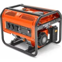
| Product type | Portable generator |
| Brand | Husqvarna |
| Model | G1300P |
| Rated power | 1000 W |
| Maximum power | 1200 W |
| Rated voltage | 110/220 V (depending on market) |
| Rated frequency | 60 Hz |
| Phase | Single-phase |
| Engine - Displacement | 98.5 cm³ |
| Fuel type | Unleaded gasoline (max 10% ethanol) |
| Fuel tank capacity | Not specified (fill to mark) |
| Engine oil capacity | 0.45 L |
| Spark plug gap | 0.76 mm |
| Net weight | 28.0 kg |
| Gross weight | 29.2 kg |
| Package dimensions (L x W x H) | 500 x 375 x 435 mm |
| Measured/guaranteed sound power level | 95 dB(A) / 95 dB(A) |
| Starting method | Manual (recoil start) |
| Outlet sockets | 230 V 32 A socket (EU) or 120/240 V sockets (US) |
| Safety devices | AC circuit breakers, switch, ground terminal, overload protection |
| Intended use | Portable outdoor power supply |
Frequently Asked Questions - G1300P HUSQVARNA
User questions about G1300P HUSQVARNA
0 question about this device. Answer the ones you know or ask your own.
Ask a new question about this device
Download the instructions for your Generator in PDF format for free! Find your manual G1300P - HUSQVARNA and take your electronic device back in hand. On this page are published all the documents necessary for the use of your device. G1300P by HUSQVARNA.
USER MANUAL G1300P HUSQVARNA
G1300P, G2500P, G3200P, G5500P, G8500P
EN Operator's manual 2-18
To prepare the product for long-term storage....14
Technical data.... 15
EC Declaration of Conformity.... 18
Introduction
Product description
This product is a portable generator with a combustion engine.
Intended use
The product supplies electrical power to operate electrical loads in locations where there is no electrical power available. Do not use the product for other tasks.
Product overview


- Fuel valve
- Choke
- Air filter
- Starter rope handle
- Wheel
- Battery
- Power switch
- Handle
- Frame
- Fuel gauge
-
Fuel tank cap
-
AC circuit breakers
- VFT meter
- Ground terminal
- AC receptacle
12 V DC terminal
The 12 V DC terminal is a power source for 12 V DC units.

VFT meter
The VFT meter shows the voltage, frequency and total operation time of the product.

AC receptacles
The product has several AC receptacles to give power to tools and equipment. The AC receptacles are different in different market areas.
EU, 1-phase, 50 Hz
A: 2-Prong, 230 V receptacle.
B: 3-Prong, 32 A 230 V receptacle.

natural_image
Pure electrical socket diagram without any text, numbers, or symbols
natural_image
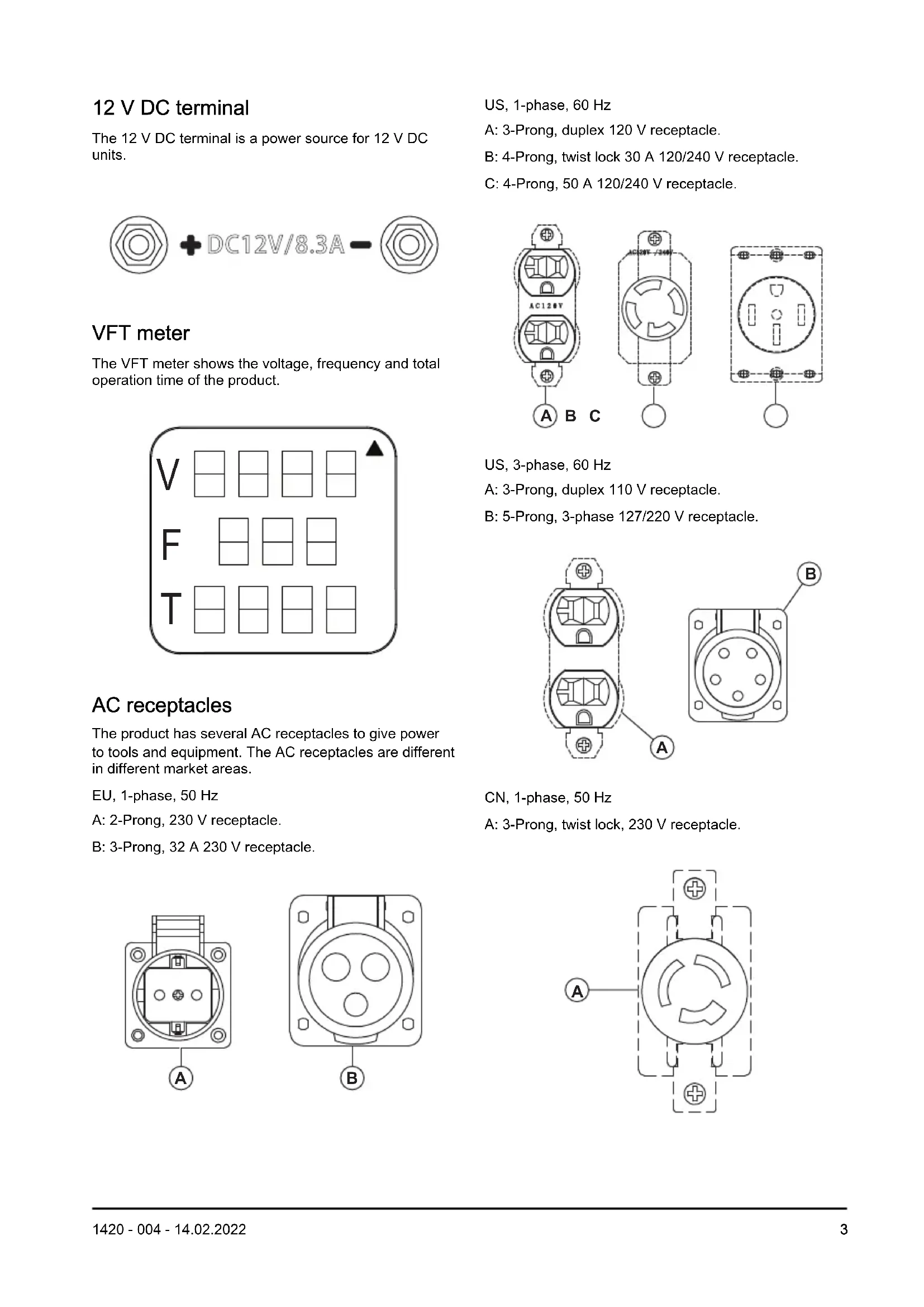
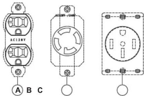
Pure electrical outlet diagram without any text, numbers, or symbolsUS, 1-phase, 60 Hz
A: 3-Prong, duplex 120 V receptacle.
B: 4-Prong, twist lock 30 A 120/240 V receptacle.
C: 4-Prong, 50 A 120/240 V receptacle.
US, 3-phase, 60 Hz
A: 3-Prong, duplex 110 V receptacle.
B: 5-Prong, 3-phase 127/220 V receptacle.

natural_image
Technical line drawing of two electrical socket components (A and B) with mounting holes and wiring, no text or symbols present.CN, 1-phase, 50 Hz
A: 3-Prong, twist lock, 230 V receptacle.

natural_image
Pure electrical circuit lines without any symbolsSymbols on the product

WARNING! Be careful and use the product correctly. This product can cause serious injury or death to the operator or others.

Read the operator's manual carefully and make sure you understand the instructions before you use this product.
Risk of fire or explosion.

Risk of carbon monoxide poisoning. Do not operate the product in areas with bad airflow.
Risk of electrical shock.
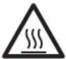
Risk of burn injury.

Add oil.
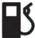
Add fuel.

Open the fuel valve.

Set the power switch to the ON position.

Set the choke to the OFF position.

Set the choke to the ON position.

Pull the starter rope handle.

Connect the electrical loads.

Disconnect the electrical loads.

Close the fuel valve.

Noise emissions to the environment according to European Directive 2000/14/EC and New South Wales legislation "Protection of the Environment Operations (Noise Control) Regulation 2017". Noise emission data can be found on the machine label and in the Technical data chapter.

Do not use the product in- doors.
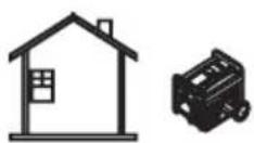
Use the product outdoors. Keep the product away from windows, doors or vents.

Set the choke to the ON position and wait for 50 seconds.
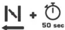
Set the choke to the OFF position and wait for 50 seconds.

Wait 30 seconds and set the power switch to the OFF position.
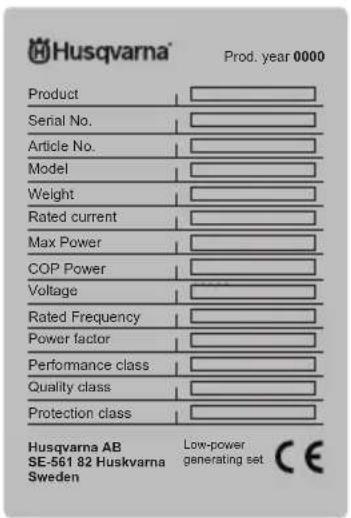
Type plate
Safety
Safety definitions
Warnings, cautions and notes are used to point out specially important parts of the manual.

WARNING: Used if there is a risk of injury or death for the operator or bystanders if the instructions in the manual are not obeyed.

CAUTION: Used if there is a risk of damage to the product, other materials or the adjacent area if the instructions in the manual are not obeyed.
Note: Used to give more information that is necessary in a given situation.
General safety instructions

WARNING: Read and understand the warning instructions that follow before you use the product.
- Read and understand the operator's manual and safety decals on the product before operation. Your safety and the safety of others is your responsibility.
- Obey the instructions in this operator's manual.
- It is not possible to give a warning for each situation that can occur during operation and maintenance of this product. Always be careful and use your common sense.
Fuel safety

WARNING: Read and understand the warning instructions that follow before you use the product.
- Gasoline is highly flammable and its vapors are explosive. Do not permit smoking, open flames, sparks or heat in the vicinity while handling gasoline.
- Never add fuel while the product is running or hot. Allow the engine to cool completely before adding fuel.
- Never fill the fuel tank indoors.
- Comply with all laws regulating storage and handling of gasoline.
- Do not overfill the fuel tank. Always allow room for fuel expansion. If the fuel tank is over-filled, fuel can overflow onto a hot engine and cause a fire or an explosion.
- Never store the product with fuel in the fuel tank where gasoline vapors might reach an open flame, spark or pilot light (as on a furnace, water heater or clothes dryer). Fire or explosion may result. Allow the product to cool entirely before storage.
- Wipe up any fuel or oil spills immediately. Ensure that no combustible materials are left on or near the product. Keep the area surrounding the product clean and free from debris. Keep a clearance of 5 ft. on all sides to allow for proper ventilation of the product.
- Do not operate the product if a connected electrical device overheat, if the electrical output is lost, or if flames or smoke are observed while the product is running.
- Keep a fire extinguisher near the product at all times.
-
Avoid spilling fuel on a hot engine.
-
Do not smoke or light cigarettes near the product or fuel.
- Drain fuel into an approved container outdoors, away from open flame. make sure that the engine is cool.
Exhaust safety

WARNING: Read and understand the warning instructions that follow before you use the product.
- Never operate the product in an enclosed area or indoors! Never use the product in the home, in a vehicle, or in partly enclosed areas such as garages, even if doors and windows are open! Only use the product outdoors and far from open windows, doors, vents, and in an area that will not accumulate deadly exhaust.
- The engine exhaust fumes contain carbon monoxide, which you cannot see or smell. This poisonous gas, if breathed in sufficient concentrations, can cause unconsciousness or even death.
- Adequate, unobstructed flow of cooling and ventilating air is critical for correct product operation. Do not alter the installation or permit even partial blockage of ventilation provisions, as this can seriously affect safe operation of the product. The product must be operated outdoors.
- Always use a battery-operated carbon monoxide alarm indoors, installed according to the manufacturers instructions.
- If you start to feel sick, dizzy, or weak after the product has been running, move to fresh air immediately. See a doctor, as you could have carbon monoxide poisoning.
Electrical safety

WARNING: Read and understand the warning instructions that follow before you use the product.
- The product produces dangerously high voltage when in operation. Avoid contact with bare wires, terminals, connections, etc., while the product is running, even on equipment connected to the product. Ensure that all appropriate covers, guards and barriers are in place before operating the product.
- Never handle any kind of electrical cord or device while standing in water, while barefoot or while hands or feet are wet. Dangerous electrical shock can occur.
-
Some countries may require the frame and external electrically conductive parts of the product be properly connected to an approved earth ground. Some countries may also require proper grounding of the product. Consult with a local electrician for grounding requirements in the area.
-
Use a ground fault circuit interrupter (GFCI) in any damp or highly conductive area (such as metal decking or steel work).
- Do not use worn, bare, frayed or otherwise damaged electrical cord sets with the product.
- In case of accident caused by electric shock, immediately shut down the source of electrical power. If this is not possible, attempt to free the victim from the live conductor. Avoid direct contact with the victim. Use a non-conducting implement, such as a rope or board, to free the victim from the live conductor. If the victim is unconscious, apply first aid and get immediate medical help.
Safety instructions for operation

WARNING: Read and understand the warning instructions that follow before you use the product.
- Only operate the product on level surfaces and where it will not be exposed to excessive moisture, dirt, dust or corrosive vapors.
- Keep hands, feet, clothing, etc., away from drive belts, fans, and other moving parts. Never remove any fan guard or shield while the unit is operating.
- Certain parts of the generator get extremely hot during operation. Keep clear of the generator until it has cooled to avoid severe burn injuries.
- Do not operate the product in rain.
- Do not alter the construction of the product or change controls which might create an unsafe operating condition.
- Never start or stop the product with electrical loads connected to receptacles and with connected devices turned on. Start the engine and let it stabilize before connecting electrical loads. Disconnect all electrical loads before shutting down the generator.
- Do not insert objects through the cooling slots of the product, even if the engine is not running.
- When working on this equipment, remain alert at all times. Never work on the equipment when physically or mentally fatigued.
- Never use the product or any of its parts as a step. Stepping on the product can stress and break parts, and may result in dangerous operating conditions from leaking exhaust gases, fuel leakage, oil leakage, etc.
- Make sure that you have knowledge about all controls and adjustments before operation.
- Do not overload the product. Also, do not overload individual panel receptacles. These outlets are protected against overload with circuit breakers. If amperage rating of any circuit breaker is exceeded, that breaker opens and electrical output to that receptacle is lost.
- Never start or stop engine with electrical devices plugged into the receptacles and devices turned on.
Safety devices on the product

WARNING: Read the warning instructions that follow before you use the product.
- Do not use a product with defective safety devices.
- Do a check of the safety devices regularly. If the safety devices are defective, speak to your Husqvarna service agent.
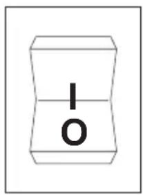
Power switch
Use the power switch to start and stop the engine.
natural_image
Simple concentric circle diagram with a small irregular shape inside, no text or symbols present.Circuit breakers
The circuit breakers prevents overload in the product. Information about rated value of the circuit breaker is shown near the circuit breaker.

Ground terminal
The ground terminal makes sure that the product is correctly grounded. Before each operation, a ground wire must be connected to the ground terminal.

natural_image
Pure electrical circuit symbol diagram with concentric circles and a plus sign (no text or labels)Safety instructions for maintenance

WARNING: Read and understand the warning instructions that follow before you do maintenance on the product.
- For safety reasons, the manufacturer recommends that the maintenance of this equipment is carried out by an Authorized Dealer. Inspect the generator regularly, and contact the nearest Authorized Dealer for parts needing repair or replacement.
- This product is equipped with a muffler that has a spark arrester. The spark arrester must be maintained in effective working order by the owner/operator.
- The exhaust system must be properly maintained. Do nothing that might make the exhaust system unsafe or non-compliant with local codes and/or standards.
- Before performing maintenance on the product, disconnect the engine starting battery (if equipped) to prevent accidental start up. Disconnect the cable from the battery terminal indicated by a negative, NEG or (-) first. Reconnect that cable last.
- Any attempt to crank or start the engine before it has been properly serviced with the recommended oil may result in engine failure.
- When working on the product, always disconnect the spark plug cap from spark plug and keep the spark plug cap away from the spark plug.
- Hot oil may cause burns. Allow engine to cool before draining oil. Avoid prolonged or repeated skin exposure to used oil. Thoroughly wash exposed areas with soap.
- The warranty of the product does not cover items that have been subjected to operator abuse of negligence. To receive full value from the warranty, the operator must maintain the product as instructed in this operator's manual.
Assembly
Introduction

WARNING: Read and understand the safety chapter before you assemble the product.
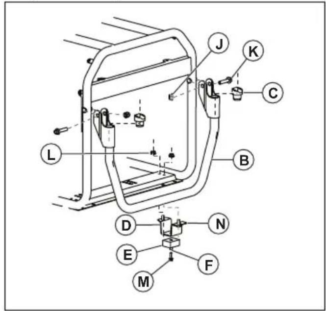
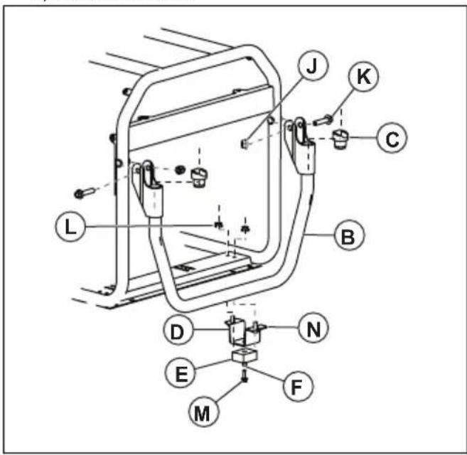
To assemble the accessory kit (G5500P, G8500P)
- Learn the parts of the accessory kit.
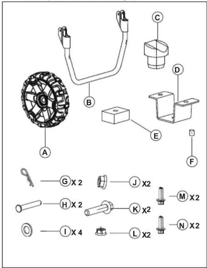
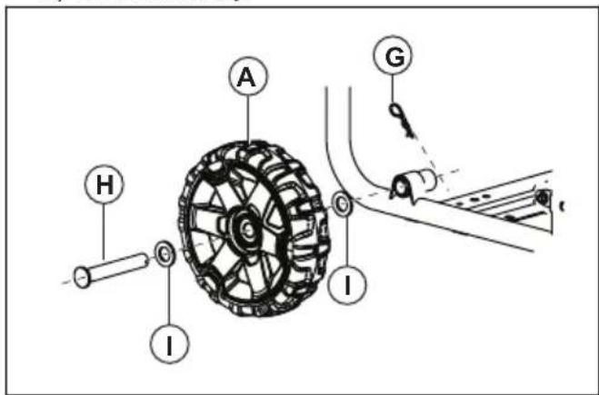
- Assemble the accessory kit. Refer to the illustrations. a) Wheel assembly:
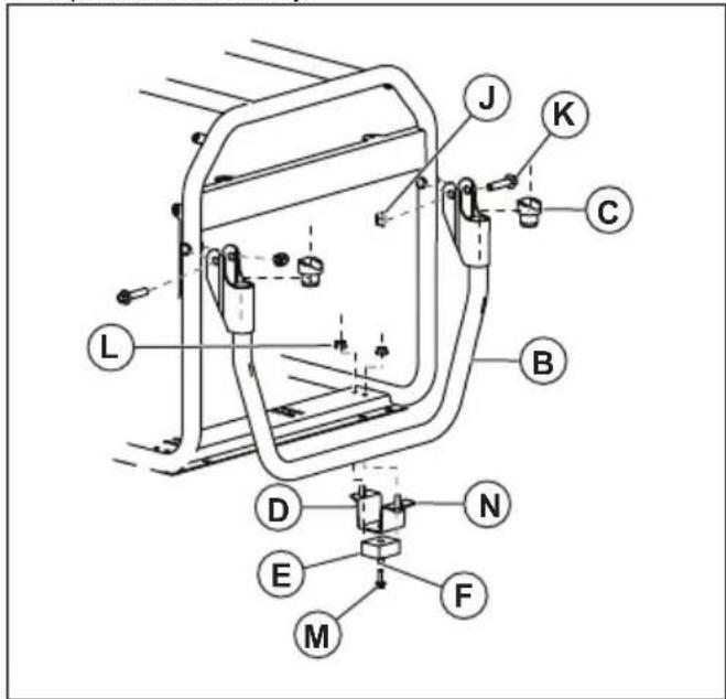
b) Handle assembly:
Installation
Introduction

WARNING: Read and understand the safety chapter before you install the product.
To ground the product

WARNING: The product must be grounded by a person with good experience and knowledge in the field of electricity. In some areas an approved electrician must do the installation. Obey local regulations.
- Install a ground rod at a minimum of 24 in. into the ground.

WARNING: The ground rod must be made of brass or copper.
- Connect a 2.5 mm 2 ground wire from the ground terminal on the control panel to a ground rod.
Note: The ground wire and the ground rod are not supplied with the product.
To connect the product to the electrical system of a building
some areas an approved electrician must do the installation. Obey local regulations.

WARNING: The product must be grounded by a person with good experience and knowledge in the field of electricity. In
- Use a manual transfer switch to connect the product to an electrical system.
• Make sure that you do the procedure in compliance with all national and local regulations.
Operation
Introduction

WARNING: Read and understand the safety chapter before you use the product.
To fill fuel
Use unleaded gasoline. Do not use gasoline with more than 10% ethanol and do not use E85 gasoline.

CAUTION: Do not mix gasoline with oil.
- Stop the engine and let the product become cool. Refer to To stop the product on page 10.
- Make sure that the product is on level ground and in an area with good airflow.
- Remove the fuel tank cap.
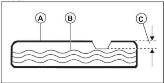
- Carefully fill the fuel tank (A). Fill fuel (B) to the mark (C).
- Clean the product from fuel spillage.

CAUTION: Fuel spillage is a fire risk and can cause damage to the environment.
To start the product
- Disconnect all electrical loads from the receptacles on the control panel.
- Make sure that the product is on a level surface.
-
Open the fuel valve.
-
Set the power switch (A) to the ON position.

natural_image
Technical line drawing of a mechanical assembly with labeled component A (no text or symbols beyond label)- Set the choke to the OFF position.
- Pull the starter rope handle slowly until you feel resistance.
- Pull the starter rope handle quickly and with force until the engine starts.
-
For electric start, do the steps that follow.
a) Push and hold the ON/OFF/START key in the start position.
b) When the engine starts, move the ON/OFF/START key to the ON position. -
Move the choke to 12 choke position.
- When the engine runs smoothly, set the choke to the ON position.
natural_image
Technical line drawing of a mechanical assembly with no visible text or symbolsNote: For G1300P, the ON and OFF positions of the choke are at the opposite positions.
To connect the electrical loads

WARNING: Do not connect 240 (230)
V to 120 (110) V receptacles. Do not connect 3-phase electrical loads to a 1-phase product. Do not connect 50 Hz electrical loads to a 60 Hz product.
- Start the engine and let it become warm for some minutes. Refer to To start the product on page 9.
- Connect and start the electrical loads.
- Make sure that there is no overload in the product. Refer to To prevent overload in the product on page 10.
To prevent overload in the product
Overload in the product can cause damage to the product and to connected electrical devices. Do the steps that follow to prevent overload in the product.
- Add the total amount of W of all electrical devices to be connected at the same time.

CAUTION: The total W must not be more than the W capacity of the product.
- The rated W of lights can be used from light bulbs. The rated W of tools, equipment and motors can be found on a decal on the device.
- If there is no amount of W specified in the product, tool or equipment, multiply V with the rated A value.
- Always connect electrical devices with the highest start up W to the product first. Then add the W of all other connected electrical loads.
To stop the product
- Stop and disconnect the electrical loads from the receptacles on the control panel.

WARNING: Do not stop the engine if the electrical loads are on and connected to the product.
- Let the engine operate without load for 30 seconds.
- Set the power switch to the OFF position.
- Close the fuel valve.
Maintenance
Introduction

WARNING: Read and understand the safety chapter before you do maintenance on the product.
Maintenance schedule
* Clean at a more regular interval if the product is used in conditions with much dust.
** Maintenance must be done by an approved servicing dealer.
| Maintenance | Daily maintenance before operation | Maintenance interval in hours | ||||
| 20 hours or each month | 50 hours or each 3 months | 100 hours or each 6 months | 300 hours or 1 time each year | Each 2 years | ||
| Clean the product. X | ||||||
| Do a check of the engine oil level. X | ||||||
| Do a check of the air filter. X | ||||||
| Clean the air filter. X | ||||||
| Do a check of the deposit cup. X | ||||||
| Replace the engine oil. X* | ||||||
| Clean or replace the air filter. X* | ||||||
| Do a check of and clean the spark plug. X | ||||||
| Do a check of the idle speed. Adjust the idle speed if it is necessary. | X** | |||||
| Do a check of the valve clearance. Adjust the valve clearance if it is necessary. | X** | |||||
| Clean the fuel tank, fuel strainer and carburetor. X** | ||||||
| Clean the combustion chamber. X** | ||||||
| Replace the fuel lines if it is necessary. X** | ||||||
To clean the product

CAUTION: Do not use water to clean the product. Water can cause damage to the product.
- Use a moist cloth to clean the external surfaces of the product.
- Use a soft brush to remove dirt and oil.
- Use a vacuum cleaner to remove clean dirt and unwanted material from the product.
- Use compressed air to remove dirt from cooling slots and other opening on the product.

CAUTION: The pressure of the compressed air must not be more than 25 psi.
To do a check of the engine oil level

CAUTION: Do not operate the product with low engine oil level. It can cause damage to the engine.

CAUTION: Use engine oil that has SJ class, SL class, or better, from the American Petroleum Institute (API). Do not use special additives. Select a viscosity range that agrees with the ambient temperature. Refer to the illustration below.

bar
| Material | Value | | -------------- | ----- | | Synthetic 5W-30 | -10 | | SAE 30 | 10 |- Stop the product fully and make sure that the product is on level ground.
- Clean the area around the oil tank.
- Remove the oil tank cap and dipstick.
- Clean the oil from the dipstick.
- Put the dipstick back fully into the oil tank.
- Remove the dipstick.
- Examine the engine oil level on the dipstick.
- If the engine oil level is low, fill engine oil until the engine oil is to the mark (A) on the dipstick. Refer to Technical data on page 15 for the oil tank capacity.

- Do a check of the engine oil level again.
- Install the oil tank cap and dipstick.
To replace the engine oil
Note: Drain the engine oil while the engine is warm. Warm engine oil is faster to drain.

WARNING: The engine oil becomes very hot and can cause burn injuries. Let the engine become cool before you drain the engine oil.
- Clean the area around the oil drain plug (A).
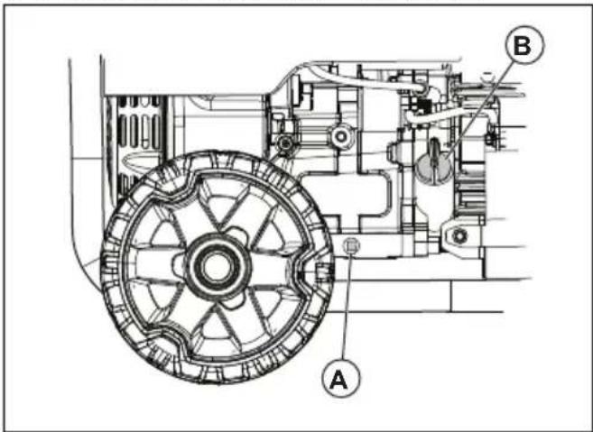
- Put an applicable fuel container below the drain hole.
- Remove the oil drain plug and the oil tank cap (B).
- Drain the engine oil into the container.
- Install the oil drain plug and tighten it.
- Fill engine oil. Refer to To do a check of the engine oil level on page 11.
- Remove oil spillage.
- Recycle the used engine oil at an approved disposal location.
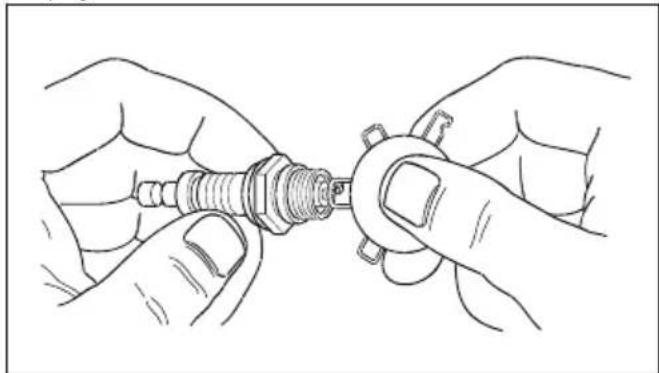
To replace the spark plug
Replace the spark plug 1 time each year.
- Stop the engine.
- Remove the spark plug cap from the spark plug.
-
Clean the area around the spark plug and remove the spark plug from the cylinder.
-
Set the electrode gap. Refer to Technical data on page 15.
natural_image
Line drawing of hands assembling a screwdriver into a housing (no text or symbols)- Install a new spark plug. Torque to 15 ft/lbs.
To do a check of the spark arrester screen
Do a check and clean the spark arrester screen 1 time each year or more frequently if it is necessary.

WARNING: In some areas and conditions, you must use a spark arrester screen to prevent the risk of fire. Obey local regulations.
- Remove the clamp (A) and the spark arrester screen (B) from the muffler (C).

- Clean the spark arrester screen with commercial solvent.
- Examine the spark arrester screen for wear and damage. Replace the spark arrester screen if it is necessary.

CAUTION: Do not use a product with a damaged spark arrester screen.
To do a check of the air filter
- Remove the knob (A) and the air filter cover (B).

- Remove the air filter (C).
- Clean the air filter and the air filter cover with soap water.
- Let the air filter and the air filter cover become dry.
- Install the air filter, the air filter cover and the knob.
Troubleshooting
Troubleshooting schedule
| Problem Cause Solution | ||
| The engine stops when it has too much load. | The air filter is not clean. Clean or replace the air filter. | |
| The engine is not warm. Let the engine become warm before operation. | ||
| The engine misfires. The spark plug is | loose. Do a check of the wire connections. | |
| Incorrect electrode gap. Replace the spark plug cap. | ||
| The spark plug cap is damaged. Replace the spark plug cap. | ||
| Expired or low quality gasoline. Fill fuel. | ||
| Incorrect compression. Adjust the compression. | ||
| The engine stops suddenly. The engine | oil level is low. Fill engine oil. | |
| The fuel tank is empty or has low quality gasoline. | Fill fuel. | |
| Defective fuel tank cap. Replace the fuel tank cap. | ||
| Defective magnet. Speak to an approved servicing dealer. | ||
| The spark plug cap is not correctly installed. | Install the spark plug cap. | |
| Engine knocking occurs. Expired or low quality gasoline. Fill fuel. | ||
| Overload in the engine. Refer to To prevent overload in the product on page 10. | ||
| Mechanical problem. Speak to an approved servicing dealer. | ||
| Engine backfire occurs. Low quality gas | soline. Fill fuel. | |
| The engine is too cold. Use fuel for cold conditions and oil additives. | ||
| The inlet valve is blocked or the engine is too hot. | Speak to an approved servicing dealer. | |
| Incorrect ignition timing. Do a check of the ignition timing. | ||
| The product has no power. The product | is not connected to the electrical source. | Stop the product and disconnect it. Connect the product and start it again. |
| A circuit breaker has tripped. Stop the product and disconnect it. Restart the circuit breaker. Connect the product and start it again. | ||
| The receptacle is engaged. Stop the product and disconnect it. Do a test of the receptacle. If the receptacle is not damaged, start and connect the product again. | ||
| Servicing is necessary. Speak to an approved servicing dealer. | ||
| The product does not operate correctly. | Problem with an electrical device. Disconnect the electrical device. Speak to an approved servicing dealer. | |
| There is too much load in the product. | Decrease the quantity of electrical devices connected to the product. | |

CAUTION: Speak to an approved servicing dealer if the problem stays.
To prepare the product for long-term storage
Do the steps that follow if the product will be kept in storage for more than 30 days. The procedure that follows prevents problems with the fuel system.
- Add a fuel stabilizer to the fuel. The fuel stabilizer must agree with the recommendation from the manufacturer.
- Operate the product for 10-15 minutes.
- Let the engine become cool and drain the fuel tank.

CAUTION: Do not keep fuel in long-term storage. Discard gasoline that is not clean.
- Start the engine and let it operate until all the fuel has been used and the product stops.
- Let the engine become cool and replace the engine oil.
-
Remove the spark plug cap and put 12 oz/15 ml of engine oil into the cylinder.
-
Put a cloth on the spark plug hole for protection.
- Pull the starter rope handle 5 times to lubricate the engine parts.
- Install and tighten the spark plug.

WARNING: Do not install the spark plug cap.
- Clean the product.
- Put the product in a clean and dry location indoors.
- Put a cover on the product for protection.

WARNING: Do not put a cover on the product if it is warm.
Technical data
Technical data
| HusqvarnaG1300P | HusqvarnaG1300P | HusqvarnaG2500P | HusqvarnaG2500P | HusqvarnaG3200P | |
| Engine displacement, cc | 98.5 98.5 196 196 | 212 | |||
| Peak power, W1 | 1000 1200 2200 2800 3000 | ||||
| Rated power, W 800 | 1000 2000 2500 | 2800 | |||
| Voltage, V 230 110 | /220,120/240 230 | 110/220,120/240 230 | |||
| Rated frequency, Hz | 50 60 50 60 50 | ||||
| Phase 1 1 1 1 1 | |||||
| Net weight, kg 28.0 | 28.0 43.0 43.0 49.0 | ||||
| Gross weight, kg 29.2 | 29.2 29.2 45.0 45.0 51.0 | ||||
| Package size, mm | 500X375X435 500 | X375X435 500X375 | X435 500X375X435 | 625X495X495 | |
| Oil tank capacity, l | 0.45 0.45 0.6 0.6 0.6 | ||||
| Electrode gap, mm/in. | 0.76/0.030 0.76/0.030 0.76/0.030 0.76/0.030 | ||||
| Type Gasoline Gasoline Gasoline Gasoline | |||||
| Measured Sound Power Level, dB (A) | 95 95 96 | ||||
| Guaranteed Sound Power Level, dB (A) | 95 95 96 | ||||
| HusqvarnaG3200P | HusqvarnaG5500P | HusqvarnaG5500P | HusqvarnaG8500P | HusqvarnaG8500P | |
| Engine displacement, cc | 212 389 389 458 458 | ||||
| Peak power, W2 | 3200 5500 6000 8000 8500 | ||||
| Rated power, W 30 | 000 5000 5500 7500 | 8000 | |||
| Voltage, V 110/220 | 120/240 230 110/2 | 20,120/240 230 110 | /220,120/240 | ||
| Rated frequency, Hz | 60 50 60 50 60 | ||||
| Phase 1 1 1 1 1 | |||||
| Net weight, kg 49.0 | 88.0 88.0 106.4 106.4 | ||||
| Gross weight, kg 5 | 1.0 91.0 91.0 109.5 | 109.5 | |||
| Package size, mm | 625X495X495 720 | X560X585 720X560 | X585 720X560X585 | 720X560X585 | |
| Oil tank capacity, l | 0.6 1.1 1.1 1.1 1.1 | ||||
| Electrode gap, mm/in. | 0.76/0.030 0.76/0.030 0.76/0.030 0.76/0.030 | ||||
| Type Gasoline Gasoline Gasoline Gasoline | |||||
| Measured Sound Power Level, dB (A) | 96 | ||||
| Guaranteed Sound Power Level, dB (A) | 96 | ||||
Watt reference guide
Note: All numbers are approximate. Refer to the data label on the appliance for wattage requirements.
| Device Running W | Additional start-up W | |
| Emergency | ||
| Refrigerator/freezer | 700 | 1500 |
| Radio | 100 | 0 |
| Job site | ||
| Air compressor - 1⁄2 HP 1000 | 1000 | |
| Table saw - 10" | 1700 | 1300 |
| Belt sander - 3" | 1200 | 1200 |
| Hand drill - 1⁄2" | 600 | 600 |
| Halogen work light | 1000 | 0 |
| Reciprocating saw | 900 | 900 |
| Recreation | ||
| AM/FM radio | 100 | 0 |
| Device Running W Additional start-up W | ||
| Electric grill 1700 0 | ||
| Inflation pump 50 100 - | ||
| CD/DVD player 100 0 | ||
| Box fan - 20" 200 200 | ||
| Coffee maker 600 0 | ||
| Household | ||
| Computer with monitor 800 0 | ||
| Electric clothes dryer 5500 500 | ||
| Electric range 2100 0 | ||
| Electric water heater 2000 0 | ||
| Light bulb - 100 W 100 0 | ||
| Microwave - 1000 W 1000 200 | ||
| Sump pump - 1⁄2 HP 1000 1100 | ||
| Television 400 0 | ||
| Washing machine | 1100 1100 | |
| Well pump - 1⁄2 HP 1000 1000 | ||
| Lawn and garden | ||
| Hedge trimmer | 400 400 | |
| Pressure washer | 1200 1200 | |
| Lawn mower | 1200 1200 | |
| Edger | 1000 1000 | |
| Heating and cooling | ||
| Central AC - 10000 BTU | 1500 1500 | |
| Furnace fan - 1⁄2 HP | 900 1400 | |
| Space heater | 1800 0 | |
| Window AC - 10000 BTU | 1200 600 | |
EC Declaration of conformity
For the following machinery:
- Product name: Portable Generator
• Function: Low-power generating set
• Model No.: G 2500P, G 3200P - Serial No.: 1945013770, 1945013793 and onwards
is herewith confirmed to fulfill all the relevant provisions of
• Machinery Directive (2006/42/EC)
- Low Voltage Directive (2014/35/EU)
- Restriction of Hazardous Substances (RoHS) Directive (2011/65/EU)
• Electromagnetic Compatibility Directive (2014/30/EU)
- Noise Emission Directive by equipment for use outdoors (2000/14/EC + 2005/88/EC)
and the following harmonized standard has been complied with:
• EN ISO 8528-13:2016, EN 61000-6-1:2007; EN 55012:2007+A1
Conformity Assessment Procedure: 2000/14/EC, amended by 2005/88/EC- Annex VI
TÜV Rheinland LGA Products GmbH, Notified Body for Machinery (notified under 0197), Tillystraße 2
- 90431 Nürnberg, Germany, carried out the noise certification. For information about noise emissions, refer to Technical data on page 15.
Huskvarna, 2020-06-10
Δdu
Claes Losdal, Development Manager/Garden Products (Authorized representative for Husqvarna AB and responsible for technical documentation).
Съдържание
Въведение....19
Безопасност....22
Монтаж....25
Инсталиране....26
Операция.... 27
Поддръжка....28

natural_image
Line drawing of a circular electrical outlet with three internal components and mounting flanges (no text or symbols)САЩ, 1-фазен, 60 Hz
A: 3-полюсен двоен контакт, 120 V.
natural_image
Technical line drawing of two electrical socket components (A and B) with mounting holes and wiring, no text or symbols present.Китай, 1-фазен, 50 Hz
Безопасност
Дефиниции за безопасност
natural_image
Simple concentric circle diagram with a small irregular shape inside, no text or symbols present.natural_image
Simple geometric diagram of concentric hexagons within a circle (no text or symbols)
natural_image
Pure electrical circuit symbol for a diode (no text or labels)Инсталиране
Въведение

natural_image
Technical line drawing of a mechanical assembly (no text or symbols visible)natural_image
Technical line drawing of a mechanical assembly with no visible text or symbolsnatural_image
Line drawing of two hands holding a screwdriver (no text or symbols present)
natural_image
Technical line drawings of two electrical socket components labeled A and B, showing internal wiring and mounting holes (no text or symbols beyond labels)USA, 1 fáze, 60 Hz
natural_image
Technical line drawing of two electrical socket components (labeled A and B), no text or symbols present.CN, 1 fáze, 50 Hz
A: 3kolíková zásuvka, 230 V, s mechanismem Twist Lock.

flowchart
graph TD
    A["Terminal A"] --> B["Switch"]
    B --> C["Component 1"]
    B --> D["Component 2"]
    B --> E["Component 3"]
    B --> F["Component 4"]
    B --> G["Component 5"]
Symboly na výrobku

Bezpečnost
natural_image
Simple concentric circle diagram with a central irregular shape, no text or symbols present.Přerušovače obvodu
natural_image
Pure geometric symbols: a hexagon with concentric circles and a plus sign (no text or labels)Instalace
Úvod

natural_image
Technical line drawing of a mechanical assembly with labeled component A (no text or symbols beyond label)natural_image
Technical line drawing of a mechanical assembly with no visible text or symbolsnatural_image
Line drawing of hands assembling a screwdriver into a housing (no text or symbols)
natural_image
Technical line drawing of a circular electrical outlet with three internal holes and mounting flanges (no text or symbols)natural_image
Technical line drawing of two electrical socket components (labeled A and B), no text or symbols present.natural_image
Pure electrical circuit lines without any symbolsΣύμβολα στο προϊόν

Ασφάλεια
natural_image
Simple concentric circle diagram with a central arrow-like shape inside, no text or symbols present.Ασφαλειοδιακόπτες
natural_image
Simple geometric diagram of concentric hexagons inside a circle (no text or symbols)
natural_image
Pure electrical circuit symbol for a diode (no text or labels)Εγκατάσταση
Εισαγωγή

natural_image
Technical line drawing of a mechanical assembly with labeled component A (no text or symbols beyond label)natural_image
Technical line drawing of a mechanical assembly with no visible text or symbolsnatural_image
Line drawing of hands holding a screwdriver (no text or symbols present)
natural_image
Technical line drawing of two electrical socket components (A and B) with mounting holes and wiring, no text or symbols present.Seguridad
natural_image
Simple concentric circle diagram with a central leaf-like shape, no text or symbols presentDisyuntores
natural_image
Simple geometric diagram of concentric circles with no text or symbols
natural_image
Pure electrical circuit symbol for a diode (no text or labels)Instalación
Introducción

natural_image
Technical line drawing of a mechanical assembly (no text or symbols visible)natural_image
Technical line drawing of a mechanical assembly with no visible text or symbolsnatural_image
Line drawing of two hands assembling a screw component (no text or symbols)
natural_image
Technical line drawing of two electrical socket components (A and B) with mounting holes and internal circuitry, no text or symbols present.US, monophasée, 60 Hz
natural_image
Technical line drawing of two electrical socket components (A and B) with no text or symbolsCN, monophasée, 50 Hz
natural_image
Pure electrical circuit lines without any symbolsSécurité
natural_image
Simple concentric circle diagram with a central arrow-like shape inside (no text or symbols)Disjoncteurs
natural_image
Pure electrical circuit symbol for a hexagonal nut and a diode (no text or labels)Installation
Introduction

natural_image
Technical line drawing of a mechanical assembly with labeled component A (no text or symbols beyond label)natural_image
Technical line drawing of a mechanical assembly with no visible text or symbolsnatural_image
Line drawing of two hands assembling a screwdriver (no text or symbols present)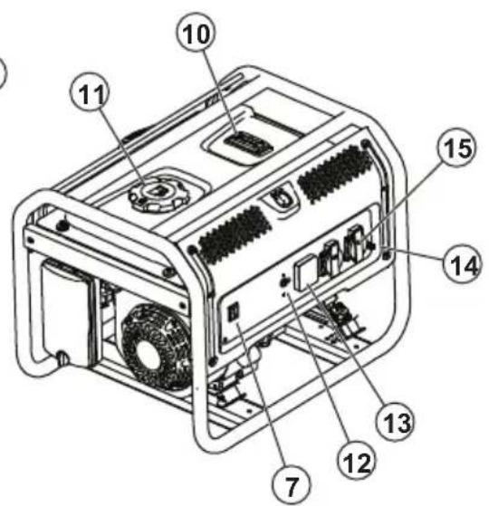
natural_image
Technical line drawings of two electrical socket components labeled A and B, showing internal wiring and mounting holes (no text or symbols beyond labels)natural_image
Technical line drawing of two electrical socket components (A and B) with no text or symbolsnatural_image
Pure electrical circuit lines without any symbolsBiztonság
natural_image
Simple concentric circle diagram with a small irregular shape inside, no text or symbols present.Áramkör-megszakítók
natural_image
Pure geometric symbols: a hexagon with concentric circles and a plus sign, no text or labels present.Telepítés
Bevezetés

natural_image
Technical line drawing of a mechanical transmission system (no text or labels)natural_image
Technical line drawing of a mechanical assembly with no visible text or symbolsnatural_image
Line drawing of two hands assembling a screwdriver (no text or symbols present)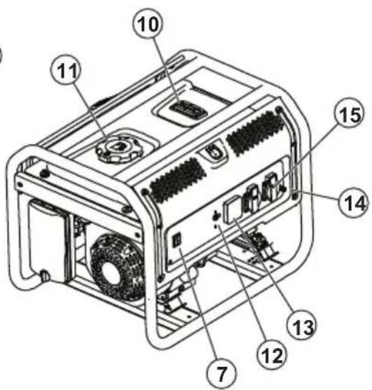
Misuratore digitale
natural_image
Technical line drawing of two electrical socket components (A and B) with no text or symbolsCN, monofase, 50 Hz
A: Presa twist lock a 3 poli da 230 V.

natural_image
Pure electrical circuit lines without any symbolsSicurezza
natural_image
Simple concentric circle diagram with a small irregular shape at center (no text or symbols)natural_image
Pure electrical circuit symbol for a hexagonal nut and a diode (no text or labels)Installazione
Introduzione

natural_image
Technical line drawing of a mechanical assembly (no text or symbols visible)natural_image
Technical line drawing of a mechanical assembly with no visible text or symbolsnatural_image
Line drawing of two hands assembling a screw component (no text or symbols)
Licznik VFT
natural_image
Technical line drawings of two electrical socket components labeled A and B, showing internal wiring and mounting holes (no text or symbols beyond labels)natural_image
Technical line drawing of two electrical socket components (A and B) with mounting holes and wiring, no text or symbols present.natural_image
Pure electrical circuit lines without any symbolsBezpieczeństwo
natural_image
Simple concentric circle diagram with a small irregular shape inside, no text or symbols present.natural_image
Pure electrical circuit symbol for a hexagonal nut and a diode (no text or labels)b) Montaż uchwytu:
Instalacja
Wstęp

natural_image
Technical line drawing of a mechanical assembly with labeled component A (no text or symbols beyond label)natural_image
Technical line drawing of a mechanical assembly with no visible text or symbolsnatural_image
Line drawing of hands holding a screwdriver (no text or symbols present)
natural_image
Technical line drawings of two electrical socket components labeled A and B, showing internal wiring and mounting holes (no text or symbols beyond labels)CN, monofásico, 50 Hz
A: Conector "twist lock" de 3 pinos, 230 V.

natural_image
Pure electrical circuit lines without any symbolsSímbolos no produto

Segurança
natural_image
Simple concentric circle diagram with a small irregular shape inside, no text or symbols present.Disjuntores
natural_image
Pure electrical circuit symbol for a diode (no text or labels)Instalação
Introdução

natural_image
Technical line drawing of a mechanical assembly with labeled component A (no text or symbols beyond label)natural_image
Technical line drawing of a mechanical assembly with no visible text or symbolsLigar as cargas elétricas

natural_image
Line drawing of two hands assembling a screw component (no text or symbols)
natural_image
Technical line drawing of two electrical socket components labeled A and B, showing internal wiring and mounting holes (no text or symbols beyond labels)natural_image
Technical line drawing of two electrical socket components (A and B) with mounting holes and internal compartments, no text or symbols present.natural_image
Pure electrical circuit lines without any symbolsSiguranță
natural_image
Simple concentric circle diagram with a small irregular shape inside, no text or symbols present.natural_image
Pure geometric symbols: a hexagon with concentric circles and a plus sign (no text or labels)Instalare
Introducere

natural_image
Technical line drawing of a mechanical assembly (no text or symbols visible)natural_image
Technical line drawing of a mechanical assembly with no visible text or symbolsnatural_image
Line drawing of two hands assembling a screw component (no text or symbols)
natural_image
Technical line drawing of an electrical outlet with three circular ports and mounting flanges (no text or symbols)US, 1-fázová, 60 Hz
A: 3-pólová, 120 V dvojzásuvka.
natural_image
Technical line drawing of two electrical socket components (A and B) with mounting holes and pinouts, no text or symbols present.natural_image
Pure electrical circuit lines without any symbolsSymboly na výrobku

Bezpečnost'
natural_image
Simple concentric circle diagram with a central leaf-like shape and an arrow, no text or symbols present.Ističe
natural_image
Pure electrical circuit symbol for a hexagonal nut and a diode (no text or labels)b) Zostava rukoväti:
Inštalácia
Úvod

VÝSTRAHA: Pred montážou
zariadenia si riadne prečítajte kapitolu o bezpečnosti.
natural_image
Technical line drawing of a mechanical assembly with labeled component A (no text or symbols beyond label)natural_image
Technical line drawing of a mechanical assembly with no visible text or symbolsnatural_image
Line drawing of two hands assembling a screw component (no text or symbols)-
Sitko lapača iskier očistite pomocou komerčného rozpúšt'adla.
-
Skontrolujte sitko lapača iskier kvôli znakom opotrebenia a poškodenia. V prípade potreby sitko lapača iskier vymeňte.


Çin, 1 fazlı, 50 Hz
natural_image
Pure electrical circuit lines without any symbolsGüvenlik
Güvenlik tanımları
natural_image
Simple concentric circle diagram with a small irregular shape inside, no text or symbols present.Devre kesiciler
natural_image
Pure electrical circuit symbol for a hexagonal nut and a diode (no text or labels)b) Tutma yeri grubu:

Kurulum
Giriş

natural_image
Technical line drawing of a mechanical assembly (no text or symbols visible)natural_image
Technical line drawing of a mechanical assembly with no visible text or symbolsnatural_image
Line drawing of two hands assembling a screw component (no text or symbols)2022-02-14

- Introduction
- Product description
- Intended use
- Product overview
- V DC terminal
- VFT meter
- AC receptacles
- Symbols on the product
- Type plate
- Safety
- Safety definitions
- General safety instructions
- Fuel safety
- Exhaust safety
- Electrical safety
- Safety instructions for operation
- Safety devices on the product
- Power switch
- Circuit breakers
- Ground terminal
- Safety instructions for maintenance
- Assembly
- To assemble the accessory kit (G5500P, G8500P)
- Installation
- To ground the product
- To connect the product to the electrical system of a building
- Operation
- To fill fuel
- To start the product
- To connect the electrical loads
- WARNING: Do not connect 240 (230)
- To prevent overload in the product
- CAUTION: The total W must not be more than the W capacity of the product.
- To stop the product
- WARNING: Do not stop the engine if the electrical loads are on and connected to the product.
- Maintenance
- Maintenance schedule
- To clean the product
- To do a check of the engine oil level
- To replace the engine oil
- To replace the spark plug
- To do a check of the spark arrester screen
- To do a check of the air filter
- Troubleshooting
- To prepare the product for long-term storage
- Technical data
- Watt reference guide
- EC Declaration of conformity
- Съдържание
- Безопасност
- Дефиниции за безопасност
- Инсталиране
- Въведение
- Symboly na výrobku
- Bezpečnost
- Přerušovače obvodu
- Instalace
- Úvod
- Σύμβολα στο προϊόν
- Ασφάλεια
- Ασφαλειοδιακόπτες
- Εγκατάσταση
- Εισαγωγή
- Seguridad
- Disyuntores
- Instalación
- Introducción
- Sécurité
- Disjoncteurs
- Biztonság
- Áramkör-megszakítók
- Telepítés
- Bevezetés
- Misuratore digitale
- Sicurezza
- Installazione
- Introduzione
- Licznik VFT
- Bezpieczeństwo
- Instalacja
- Wstęp
- Símbolos no produto
- Segurança
- Disjuntores
- Instalação
- Introdução
- Ligar as cargas elétricas
- Siguranță
- Instalare
- Introducere
- Bezpečnost'
- Ističe
- Inštalácia
- Güvenlik
- Güvenlik tanımları
- Devre kesiciler
- Kurulum
- Giriş
Brand : HUSQVARNA
Model : G1300P
Category : Generator