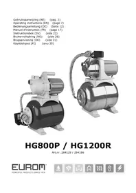
Flow HG800P - Pressure washer Eurom - Free user manual and instructions
Find the device manual for free Flow HG800P Eurom in PDF.



| Product type | Hydrophore group (pressure booster pump) |
| Brand | Eurom |
| Model | Flow HG800P |
| Power | 800 W |
| Max flow rate | 53 l/min |
| Max delivery head | 40 m |
| Max suction head | 8 m |
| Connections | 1" x 1" |
| Power supply | 230 V - 50 Hz |
| Pressure tank capacity | 20 l |
| Tank material | Plastic |
| Weight | 12.2 kg |
| Use | Clean water supply for 1 to 2 taps |
| Noise level | Insensitive (soundproofed) |
| Tank pre-charge pressure | 1.7 bar |
| Electrical protection | 30 mA circuit breaker recommended |
| Power cable type | H07RN-F (VDE0620) |
| Routine maintenance | Drain if unused for long, protect from frost |
| Warranty | Does not cover frost damage |
| Standards | CE |
Frequently Asked Questions - Flow HG800P Eurom
User questions about Flow HG800P Eurom
0 question about this device. Answer the ones you know or ask your own.
Ask a new question about this device
Download the instructions for your Pressure washer in PDF format for free! Find your manual Flow HG800P - Eurom and take your electronic device back in hand. On this page are published all the documents necessary for the use of your device. Flow HG800P by Eurom.
USER MANUAL Flow HG800P Eurom
Operating instructions (EN) (page 7)
natural_image
Two industrial pumps with metallic and gray surfaces, connected by tubing (no visible text or symbols)HG800P / HG1200R
Art.nr. 264128 / 264166
Dank
Installatie
natural_image
Symbol of a trash bin with crossed lines indicating no waste or discharge, and a solid black rectangle below (no text or labels)Thank you very much for choosing for a Eurom device. You have made a good choice! We hope you will be satisfied about its functioning. To get maximum profit from your panel, it is important to read this manual attentive and totally before use, and to understand what is written. Read especially the safety instructions: they are there to protect you and your environment. Keep the manual in a safe place for future reference. Store also the package: that is the best protection for your heater in times of no-use. And if you at any time pass the appliance on, pass on the manual and package too.
We wish you a lot of fun with the hydrophore unit!
Eurom
Kokosstraat 20
8281 JC Genemuiden (NL)
info@eurom.nl
www.eurom.nl
This manual has been complied with the utmost care. Nevertheless, we reserve the right to optimize this manual at any time and to adjust it technically. The images used may differ.
General information
This manual has been compiled to ensure correct installation and use of your EUROM HG hydrophor units. EUROM HG hydrophor units operate silently and are designed to provide one or two tap points with (clean) water in an automated manner. If you have any doubts about installation or use, but also regarding operation, malfunctions, damage, etc., please do not hesitate to consult your supplier!
EUROM HG hydrophor units are made from top quality materials, subjected to the toughest hydraulic and electrical tests and carefully inspected. By carefully following the installation and operating instructions for the pump and paying careful attention to the wiring diagrams, you will avoid potential motor overload and other problems resulting from incorrect use. The manufacturer and importer do not accept any liability for the consequences of incorrect, improper and negligent use. When the pump reaches the maximum pressure, it will be automatically switched off by the group.
Technical specifications and diagrams
| Type | HG800P | HG1200R |
| Power | 800W | 1200W |
| Capacity max. | 53 l/m | 63 l/m |
| Discharge head max. | 40m | 48m |
| Suction height max. | 8m | 8m |
| Connections | 1" – 1" | 1" – 1" |
| Supply voltage | 230V-50Hz | 230V-50Hz |
| Capacity of pressure vessel | 19 litres | 24 litres |
| Pump housing | plastic | Stainless Steel |
| Weight | 12,2 kg | 14,6 kg |
Installation
The unit should be installed in a covered, but well-ventilated place. This place must remain dry under all circumstances; if necessary, provide water drainage options. The pump on which the pressure vessel is mounted must not be connected to the water supply. This can have consequences for the water pressure, also for adjacent plots. In addition, the tank of the hydrophor unit is not suitable for drinking water.
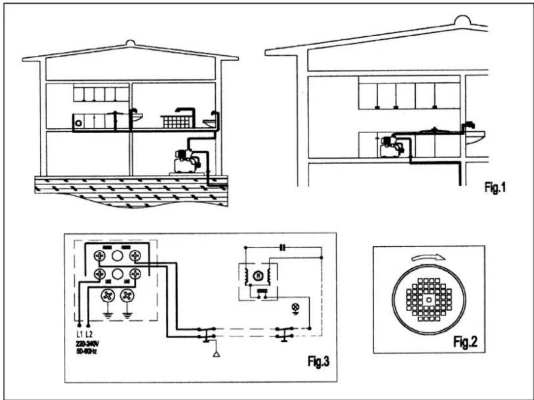
The group can further be connected to any source that provides a sufficient water yield. See also the installation diagrams.
Failure to comply with the above conditions may result in damage to the pump and the entire system!
Drainage pipes
The diameter of the pipes that drain the water should be equal to or greater than the diameter of the pump outlet. The pipes/hoses must not hold back pressure and must be checked for water tightness.
Failure to comply with the above conditions may result in damage to the pump and the installation!
Electrical connections
Always make sure that all connections and connectors between the mains (or other voltage source) and the hydrophor unit are correct and undamaged. This also applies to the cables and wires from and in the hydrophor unit. For the correct connection, see the wiring diagram (fig. 3). The appliance must be connected to an earthed power socket. The security for the installation must be equipped with an earth leakage switch of 30 mA. The power cable must comply with EEC standards or be type H07 RN-F (VDE0620). Failure to comply with the above conditions may result in damage to the pump and the entire system and creates a risk of electric shock!
Checks before start-up
Before starting up the pump for the first time, make sure that:
√ voltage and frequency of the power source correspond to the specifications on the hydrophore unit nameplate
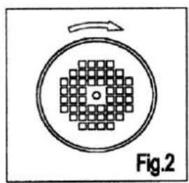
√ the pump shaft rotates smoothly and freely
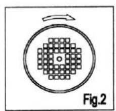
√ the pump body is completely filled with water; unscrew the relevant power plug (on top of the pump) and fill the pump.
See also the installation diagrams. Failure to comply with the above conditions may result in damage to the pump and the entire system!
Starting
Open all flow valves in the suction and discharge pipes. Turn on the power and the pump will start automatically. While doing this, the tap point should be open to allow any air in the system to escape. Afterwards, close the tap and the unit will switch itself off when the maximum pump pressure is reached. If the hydrophor unit does not work, does not build up pressure or does not switch off, first try to find the cause of the fault by consulting the fault indicator.
Maintenance
Regularly check that the pressure in the pressure vessel is sufficient as follows:
- Remove the plug from the socket
- Open the tap and drain all the water from the system
- Unscrew the black cap on the back of the pressure vessel
- Check the pressure in the boiler with a tire pressure gauge: the pressure should be 1.7 bar, if not 1.7 bar, correct the pressure.
- Put all parts back in the right place
Furthermore, the EUROM hydrophor unit requires no specific maintenance.
Nevertheless, we recommend that you drain the pump if the pump will not be used for a longer period. When it is cold and there is a risk of frost, you must drain the pump, otherwise it will suffer frost damage. Frost damage is not covered by the warranty!
If the pump will not be used for a significantly long period it should be cleaned and stored in a dry, well ventilated place.
Fault indicator
Fault:
The group does not switch off automatically: Cause and solution 2, 5 or 7
The motor is running but not supplying water: Cause and solution 4 or 5
The pressure is insufficient: Cause and solution 4, 5 or 7
The group switches on and off continuously: Cause and solution 2 or 7
The group does not start up: Cause and solution 3, 6 or 8
Cause and solution:
- Check the non-return valve in the suction hose
- Leakage at a tap. Seal the leak.
- The pump is blocked or dirty. Clean the pump or call the service department
- Water is too deep. Check the discharge head.
- Air is drawn in. Tightly seal all connections and connectors.
- No power. Check the plugs and the ground fault.
- Leakage in the drainage pipes. Seal the leak.
- The water pressure is higher than the starting pressure of the pressure switch; check if the initial settings are correct.
If malfunctions other than those mentioned above occur, or if the suggested solutions do not solve the problem, please contact your customer service.
Removal
natural_image
Symbol of a trash bin crossed with no text or labels
In the EU this symbol indicates that this product may not be disposed of as ordinary household waste. Old equipment contains valuable materials, suitable for recycling. These materials should be made suitable for reuse in order to prevent any adverse effects to health and the environment caused by unregulated waste collection. Therefore, please make sure that you bring old equipment to a designated collection point. Alternatively, contact the original supplier, who can make sure that as many of the components as possible can be recycled
CE-declaration
See page 39.
Dank
Installation
natural_image
Symbol of a trash bin with crossed lines indicating no waste or discharge, and a solid black rectangle below (no text or labels)natural_image
Cross-sectional diagram of a building interior showing internal layout and equipment (no text or labels)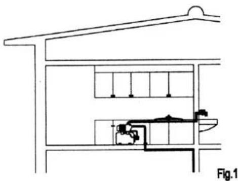
natural_image
Architectural cross-section diagram of a building facade with internal fixtures and structural elements (no text or labels)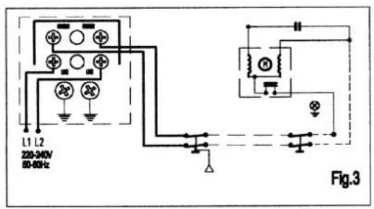
natural_image
Diagram of a circular grid pattern with an arrow indicating rotation, labeled Fig.2 (no text or symbols within the diagram itself)Installation
natural_image
Symbol of a trash bin with crossed lines indicating no waste or discharge, and a solid black rectangle below (no text or labels)natural_image
Cross-sectional diagram of a greenhouse or water treatment facility showing internal tanks, pipes, and equipment (no text or labels)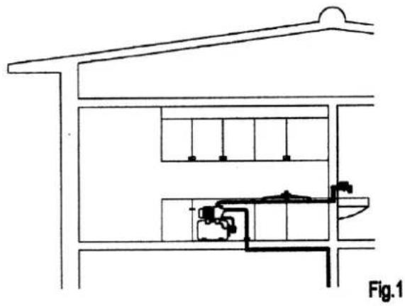
natural_image
Architectural cross-section diagram of a building facade with internal equipment and structural elements (no text or labels)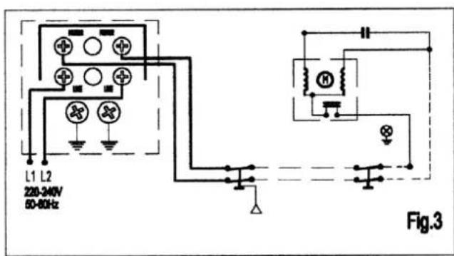
natural_image
Diagram showing a circular grid pattern with an arrow indicating rotation, labeled Fig.2 (no text or symbols on the diagram itself)Installation
Kontroller INNAN START
natural_image
Symbol of a trash bin crossed with no text or numbers, representing waste sorting or disposal (no text present)natural_image
Cross-sectional diagram of a greenhouse or aquaculture facility with tanks, pipes, and a water tank (no text or labels)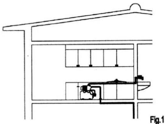
natural_image
Architectural cross-section diagram of a building showing internal layout and structural elements (no text or labels)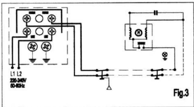
natural_image
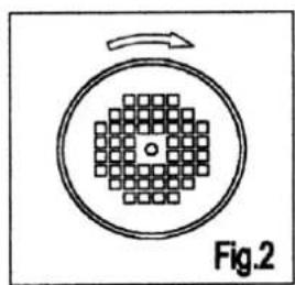
Diagram showing a circular grid pattern with an arrow indicating rotation, labeled Fig.2 (no text or symbols on the diagram itself)Installasjon
Enheten må installeres på et sted med tak, men med god lufting. Stedet må under alle omstendigheter forbli tört; om nødvendig må du sørge for at vann føres bort. Pumpen som trykkbeholderen monteres på kan ikke være tilknyttet vannettet. Dette kan nemlig ha konsekvenser for vanntrykket, også på tilgrensende eiendommer. Hydrofortanken er heller ikke egnet til drikkevann.
Hydroforen kan ellers tilknyttes til en hvillken som helst kilde som leverer nok vann. Se ellers installasjonsdiagrammene.
natural_image
Symbol of a trash bin with no text or numbers presentInstallation
natural_image
Symbol of a trash bin crossed with a diagonal line, representing no waste or discharge (no text or labels)
Asennus
natural_image
Symbol of a trash bin crossed with no text or numbers, representing waste sorting or disposal (no text present)
declares the following device in sole responsibility:
Product: hydrophore unit!
Brand name: EUROM
Model: HG800P & HG1200R
Item number: 264128 & 264166
Complies with the following harmonization rules:
Low Voltage Directive: LVD 2014/35/EU
Electromagnetic compatibility Directive: EMC 2014/30/EU
Restriction of Hazardous Substances RoHS Directive: 2011/65/EU&(EU)2015/863
Applied harmonized standards:
EN 60335-1:2012+A11+A13
EN 60335-2-41:2003+A1+A2
EN 62233:2008
AfPS GS 2014:01
EN 55014-1:2017
EN 55014-2:2015
EN 61000-3-2:2014
EN 61000-3-3:2013
Genemuiden, 17-11-2020
W.J. Bakker, alg. Dir.
Eurom
Kokosstraat 20
8281 JC Genemuiden
The Netherlands
info@eurom.nl
www.eurom.nl
171120


- HG800P / HG1200R
- Dank
- Installatie
- General information
- Technical specifications and diagrams
- Installation
- Drainage pipes
- Electrical connections
- Checks before start-up
- Starting
- Maintenance
- Fault indicator
- Fault:
- Cause and solution:
- Removal
- CE-declaration
- Kontroller INNAN START
- Installasjon
- Asennus
- Eurom
Brand : Eurom
Model : Flow HG800P
Category : Pressure washer